38 tin bismuth phase diagram
SOLIDIFICATION: BISMUTH-TIN COOLING CURVE 13 Figure 16: Phase diagram of the Bi-Sn alloy from literature (Adapted from Yeh et al., 2011). Conclusion The structure of the alloy showed the same features that the literature was reporting. The slight difference might have resulted from the fluctuating cooling temperatures. The cooling curves were also representing the solidification process that ... Phase Diagrams • Indicate phases as function of T, Co, and P. • For this course:-binary systems: just 2 components.-independent variables: T and Co (P = 1 atm is almost always used). • Phase Diagram for Cu-Ni system Adapted from Fig. 9.3(a), Callister 7e. (Fig. 9.3(a) is adapted from Phase Diagrams of Binary Nickel Alloys , P. Nash
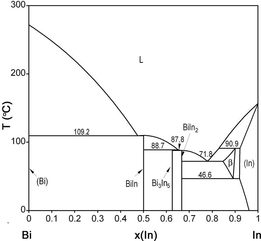
The elements bismuth and indium have relatively low melting points when compared to other metals, and their alloy Bismuth Indium is classified as a fusible alloy. It has a melting point lower than the eutectic point of the tin lead alloy. The Bi-Sn phase diagram in [Massalski2] was adopted from [Hansen], who assessed the Bi-Sn phase diagram ...

Tin bismuth phase diagram
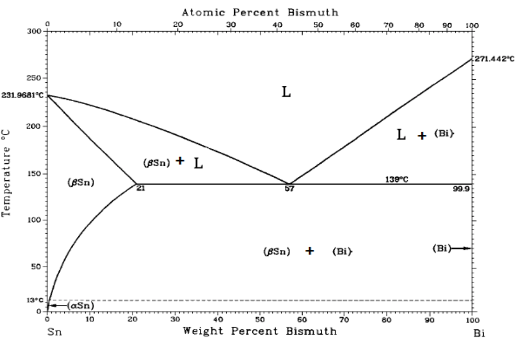
84Sak: T. Sakurai, "Construction of the Bi−Pb−Sn Ternary Phase Diagram by Means of Thermal Analysis," dissertation (GIF049), School of Science and Engineering, Waseda University, Japan (1984) in Japanese. (Ternary System; Experimental; Indicates presence of a phase diagram) The elements bismuth and indium have relatively low melting points when compared to other metals, and their alloy bismuth-indium (Bi-In) is classified as a fusible alloy.It has a melting point lower than the eutectic point of the tin-lead alloy. The most common application of the Bi-In alloy is as a low temperature solder, which can also contain, besides bismuth and indium, lead, cadmium ... As shown in the phase diagram Figure 1, at the eutectic composition, the tin-bismuth alloy melts at 139°C. In fact, the nanoparticles likely melt at a slightly lower temperature than this due to ...
Tin bismuth phase diagram. If you look closely at the Tin-Bismuth phase diagram or the lead bismuth phase diagram small amounts of bismuth will just go into a solid solution in the tin phase or the lead phase. For example ... Tin Bismuth Phase Diagram - Titania Nanotube Stabilized Biocl Nanoparticles In Visible Light characterization of eutectic sn bi solder joints springer the sn bi phase diagram 9 indicates that the eutec tic characterization of eutectic sn bi solder joints 601 500 400 s 300 2oo m 100 Tin Bismuth Phase Diagram - Crystals Free Full Text. tin tin is a chemical element with the symbol sn from latin stannum and atomic number 50 it is a post transition metal in group 14 of the periodic table. Tin Bismuth Phase Diagram - Crystals Free Full. properties of water hydrogen hydroxide hh or hoh hydrogen oxide dihydrogen monoxide ... Relative Phase Amount Determinations— Mass and Volume Fractions For the lead-tin alloy in Example Problem 9.2, calculate the relative amount of each phase present in terms of a. mass fraction b. volume fraction. At 150°C take the densities of Pb and Sn to be 11.23 and 7.24 g/cm3, respectively. 12/3/2013 11:12 PM
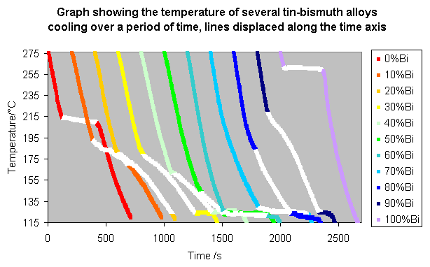
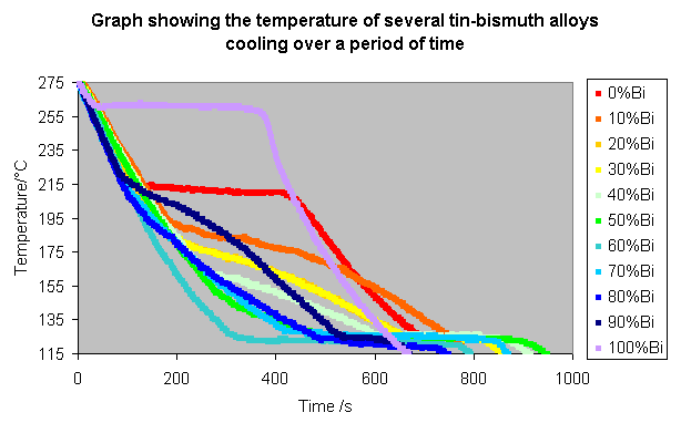
on Bismuth Tin Phase Diagram. Diagram Type: binary phase diagram. Concentration range: full composition; 0- at.%. Sn. Temperature: - °C. Nature of investigation. Bio Hi everyone, my name is Josh and this is my first post, it is quite long but I hope you find it informative. by engenuity. 3 Metals Bi - Sn - Zi. Principles. Solid-liquid phase diagrams are of great value in the technical study of alloys, ceramics and in the recovery of a salt by crystallization from a mixture of salts. The binary solid-liquid phase diagram in Figure 1 shows the stability of different phases as a function of temperature at a given pressure. An experiment can be performed to get a rough idea of a phase diagram by recording cooling curves for alloys of two metals, in various compositions. The alloy chosen for this example is bismuth-tin, both of which metals have low melting points, and so can be heated and cooled more quickly and easily in the lab. prism is a two-component temperature-composition phase diagram with Pb Triple Eutectic 3-Dimensional Depiction of Temperature-Composition Phase Diagram of Bismuth, Tin, and Lead at 1atm. The diagram has been simplified by omission of the regions of solid solubility. Each face of the triangular a eutectic.
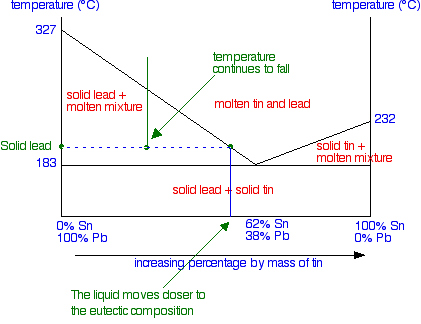
According to phase diagram of tin-bismuth binary system [75] the eutectic alloy contains 39.0 at.% of tin included into two crystalline phases of bismuth and -tin ( Figure 18). The latter ... A binary system of tin/indium (Sn/In) in the form of nanoparticles was investigated for phase transitions and structural evolution at different temperatures and compositions. The Sn/In nanosolder particles in the composition range of 24-72 wt% In were synthesized by a surfactant-assisted chemical reduction m Important: This is a simplified version of the real tin-lead phase diagram.In particular, it ignores the formation of solid solutions of tin and lead. You will find the correct diagram on this NIST web page.Beware that on that page, the tin-lead axis is reversed from the one I have drawn above - in other words 100% lead is on the right rather than the left. has been pre-tinned with a tin-lead or tin-bismuth alloy with a solder of a different composition may result in the formation of a low-melting higher-component eutectic. In this case, the multi-component phase diagram can be used to evaluate the possible effects resulting from such a contamination. Traditionally, phase diagrams are
Allen and Jesser [49] evaporated 99.99% Bi and Sn on amorphous C films to make alloys with 40 nm grains, and observed them via using in situ TEM. Fig. 7.7 shows one of their phase diagrams. The solid and dashed lines show the phase diagrams of conventional and nanoalloys, respectively. In each of the nanoalloy phase diagrams the solidus and liquidus fully move down; therefore the melting point ...
An electroless immersion plating process for depositing a tin-bismuth plate onto a surface formed of copper or the like comprises immersing the surface into an acidic aqueous solution comprising a tin alkane sulfonate compound, preferably tin methane sulfonate, and a bismuth alkane sulfonate compound, preferably bismuth methane sulfonate.
Abstract. This article is a compilation of binary alloy phase diagrams for which bismuth (Bi) is the first named element in the binary pair. The diagrams are presented with element compositions in weight percent. The atomic percent compositions are given in a secondary scale. For each binary system, a table of crystallographic data is provided ...
The phase diagram describe the relationship between composition and temperature in determining the phase fields of the various constituents of the diagram. The phase diagram is ... and tin, bismuth and cadmium, aluminum-silicon. The lead and tin binary system is reproduced in Figure 2. 183 D 400 - - 62 Sn. 100 Sn. O C 327 A E Eutectic Line
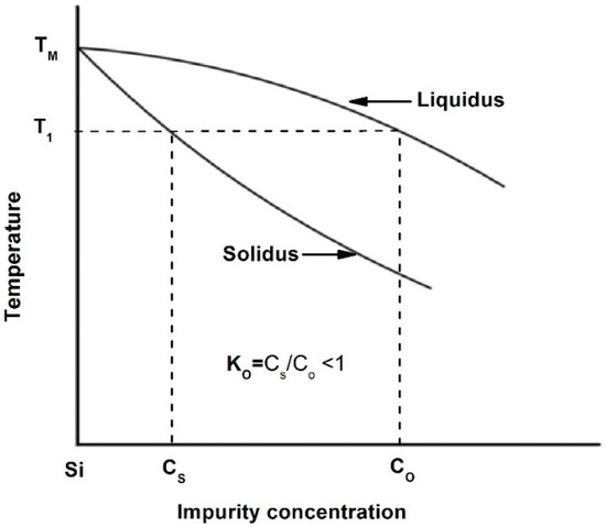
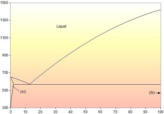
Materials Free Full Text Binary Phase Diagrams And Thermodynamic Properties Of Silicon And Essential Doping Elements Al As B Bi Ga In N P Sb And Tl Html
low enough temp. that the phase diagram shows nothing more is going on. - read the graph accordingly to determine the temperatures used for the phase diagram. - repeat with each alloy sample. ... Sample # Bismuth Tin Sample # Bismuth Tin 1 100 0 1 10 0 2 97.5 2.5 2 9.74 0.25093 3 95 5 3 9.5153 0.4999 4 90 10 4 9.039 1.0065 5 70 30 5 7.0023 2.9719
Status of the thermodynamic description: B.-J. Lee, C.-S. Oh and J.-H. Shim, J. Electron. Mater. 25 (1996) 983-991: Full thermodynamic assessment.
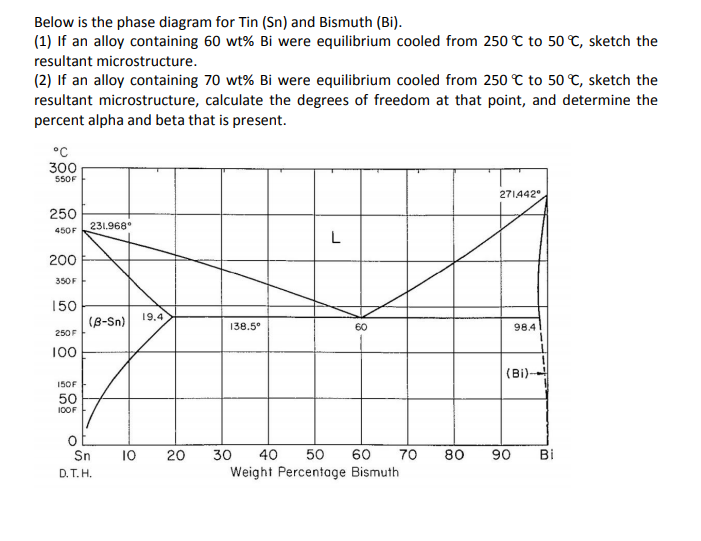
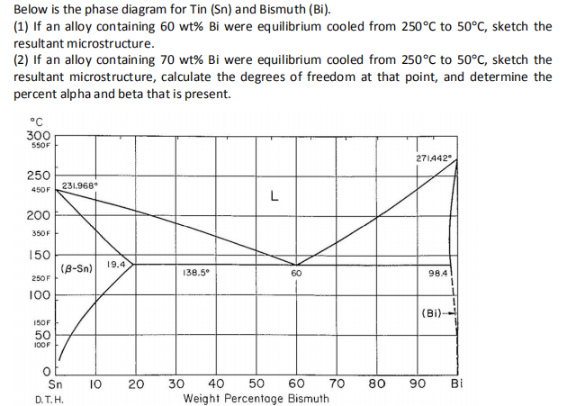
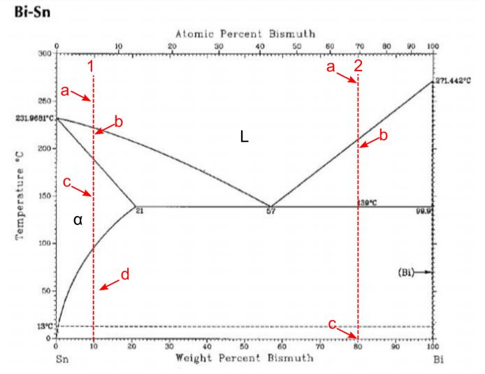
Bi-Sn (Bismuth-Tin) The Bi-Sn phase diagram in [Massalski2] was adopted from [Hansen], who assessed the Bi-Sn phase diagram data published before 1958. Since then, more experimental data on this system were reported by [ 1958Oel ], [ 1969Del ], [ 1987Gla ], and [ 2007Bra ].
tin, which melts at 232oC. In low temperature soldering a number of alloying elements can be used to reduce tin's melting temperature. Ga, In, Bi, and Cd are effective in reducing the melting temperature of solder alloys, although Cd is not often considered due to its toxicity. Gallium-containing
THE BI-SN EQUILIBRIUM PHASE DIAGRAM Mike Meier Department of Chemical Engineering and Materials Science University of California, Davis Davis, CA 95616 USA Key Words: equilibrium phase diagram, eutectic, thermocouple Prerequisite Knowledge: basic understanding of equilibrium phase diagrams, eutectic reactions, and temperature measurement using thermocouples.
Civil Engineering questions and answers. QUESTION 30 Figure 3 shows the equilibrium phase diagram for the tin-bismuth binary alloy system What phases would be expected to be present in an alloy of composition 90 wt% Sn. 10 wt% BI held at 150°C? Assume equilibrium conditions apply. (1 mark) a) (B-Sn) b) (B-Sn) + L C) (B-Sn) + (BI) d) (BI) + L ...
Alpha Tin The alpha phase of tin (white tin) exists below 13.2˚C and is shown on the tin-bismuth phase diagram located near the end of this document. The room temperature phase, βSn, is located in the large triangular region on the left of the diagram. αSn does not appear on the lead-tin diagram used in the
As shown in the phase diagram Figure 1, at the eutectic composition, the tin-bismuth alloy melts at 139°C. In fact, the nanoparticles likely melt at a slightly lower temperature than this due to ...
The elements bismuth and indium have relatively low melting points when compared to other metals, and their alloy bismuth-indium (Bi-In) is classified as a fusible alloy.It has a melting point lower than the eutectic point of the tin-lead alloy. The most common application of the Bi-In alloy is as a low temperature solder, which can also contain, besides bismuth and indium, lead, cadmium ...
84Sak: T. Sakurai, "Construction of the Bi−Pb−Sn Ternary Phase Diagram by Means of Thermal Analysis," dissertation (GIF049), School of Science and Engineering, Waseda University, Japan (1984) in Japanese. (Ternary System; Experimental; Indicates presence of a phase diagram)

Binary Phase Diagrams And Thermodynamic Properties Of Silicon And Essential Doping Elements Al As B Bi Ga In N P Sb And Tl Abstract Europe Pmc
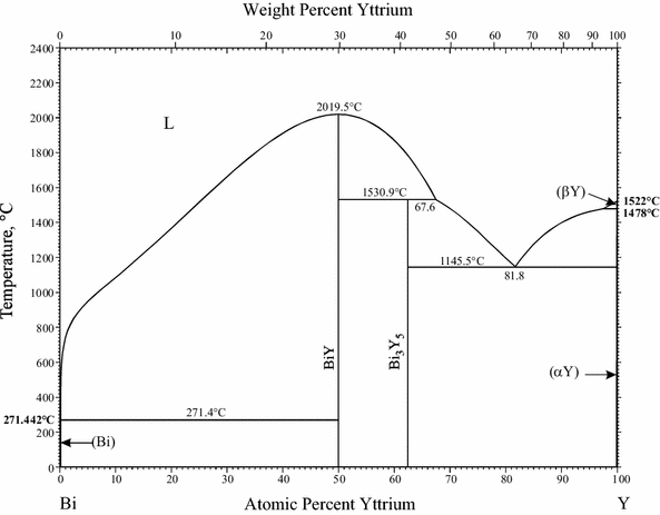
Supplemental Literature Review Of Binary Phase Diagrams Bi Ga Bi Y Ca H Cd Fe Cd Mn Cr La Ge Ru H Li Mn Sr Ni Sr Sm Sn And Sr Ti Springerlink

Binary Phase Diagrams And Thermodynamic Properties Of Silicon And Essential Doping Elements Al As B Bi Ga In N P Sb And Tl Abstract Europe Pmc

Composition And Size Modulated Porous Bismuth Tin Biphase Alloys As Anodes For Advanced Magnesium Ion Batteries Nanoscale Rsc Publishing
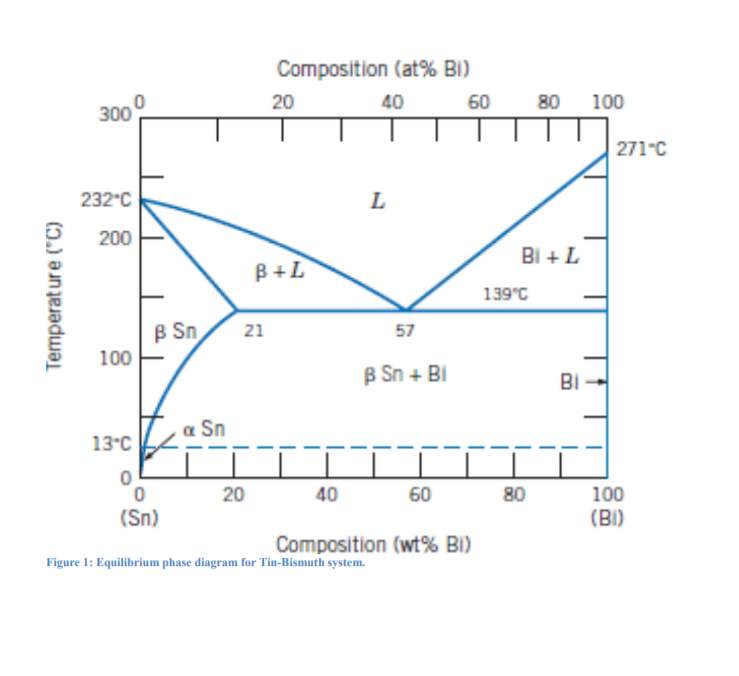
Tin Phase Diagram 35 Images Tin Silver Phase Diagram 17 Scientific Diagram Below Is The Phase Diagram Of Lead The Lead


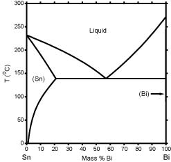










0 Response to "38 tin bismuth phase diagram"
Post a Comment