39 d2 tanabe sugano diagram
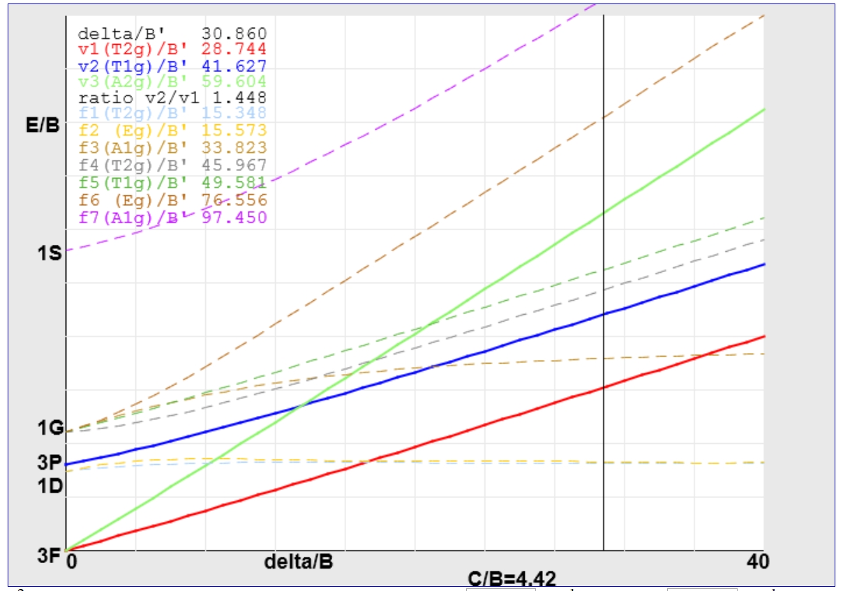
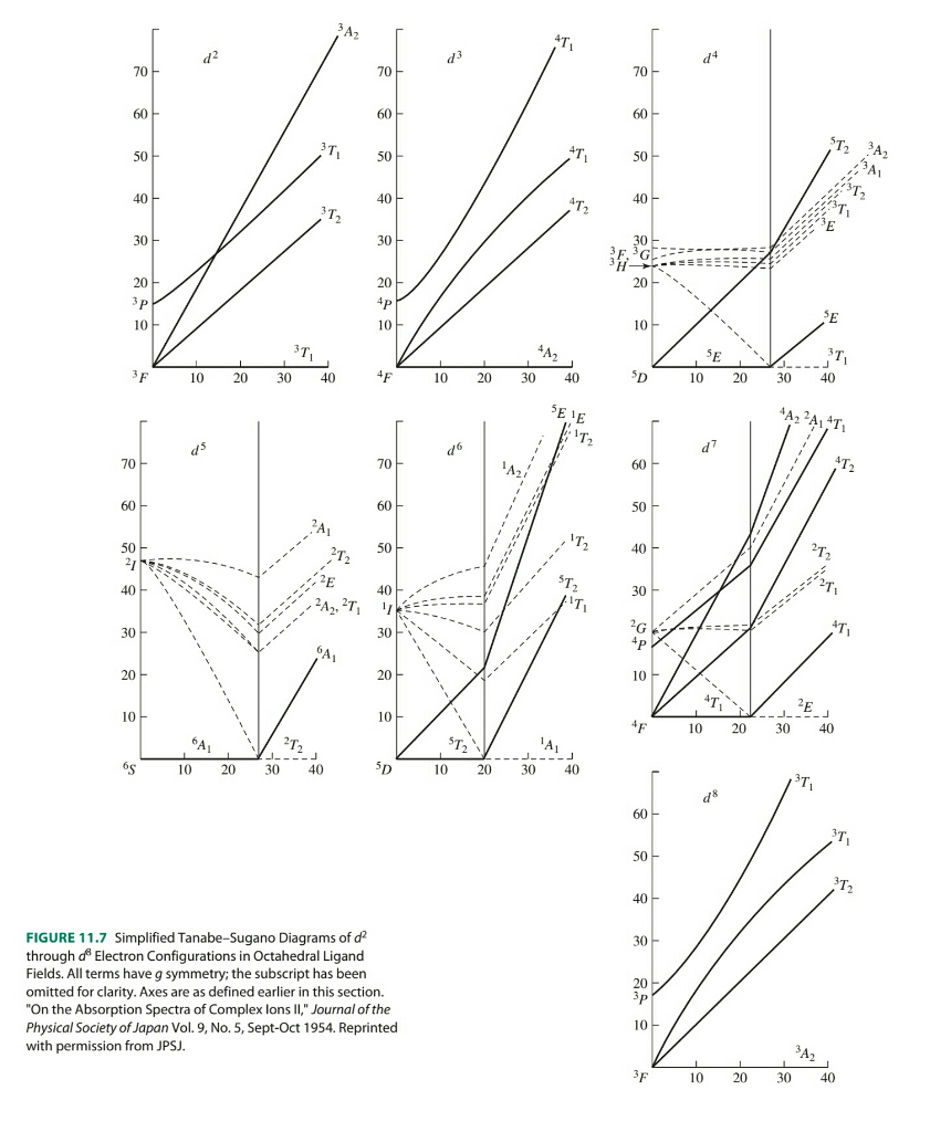
Using [V(H2O)6]3+and [Co(NH3)6]2+ as representative examples, UV-Vis data for V(III) is fit to the d2 Tanabe-Sugano diagram and known ligand field parameters... Certain Tanabe-Sugano diagrams (d4, d5, d6, and d7) also have a vertical line drawn at a specific Dq/B value, which corresponds with a discontinuity in the slopes of the excited states' energy levels. This pucker in the lines occurs when the spin pairing energy, P, is equal to the ligand field splitting energy, Dq.
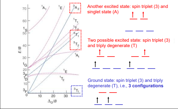
Limitations of MO Diagrams The problem: orbital energy diagrams ignore inter-electron repulsion, i.e., several states comprise the (t 2g)1(e g) 1 configuration,

D2 tanabe sugano diagram
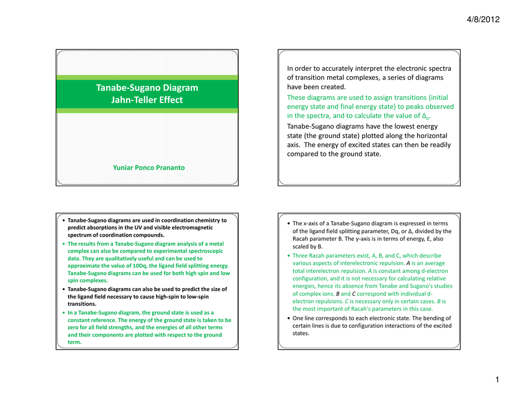
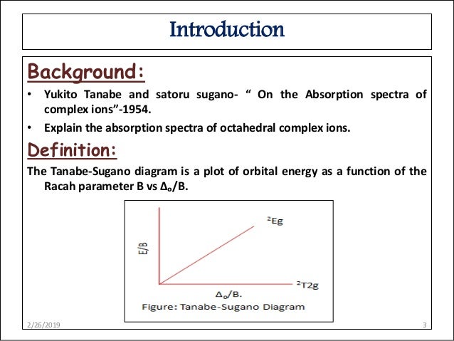
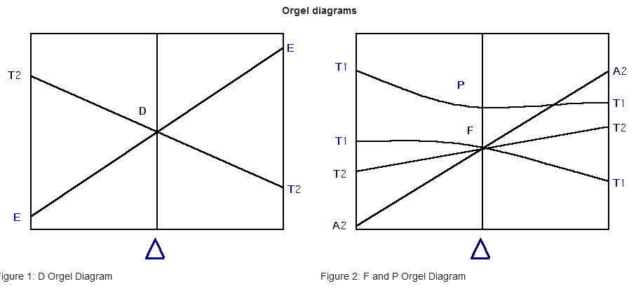
Tanabe Sugano Diagram d2 #drbeenakiscience #csir #gate #net Orgel and Tanabe-Sugano Diagrams for Transition Metal Complexes (d1 - d9 States) It is a well-known fact that electronic transitions are always accompanied by vibrational as well as rotational changes which results in a considerable broadening of the bands in the UV-visible spectra of transition metal complexes too. Tanabe-Sugano diagram for d2 octahedral complexes 2/26/2019 12 13. Advantages over Orgel diagrams • Tanabe-Sugano diagrams can be used for both high spin and low spin complexes, unlike Orgel diagrams which apply only to high spin complexes. • In a Tanabe-Sugano diagram, the ground state is used as a constant reference, in contrast to ...
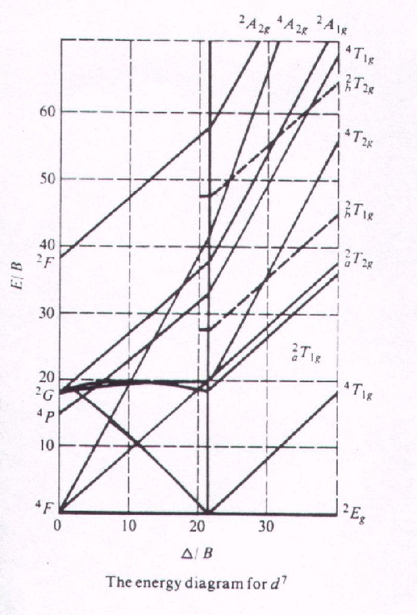
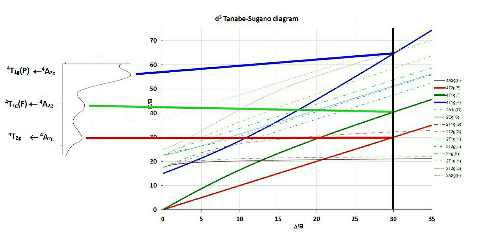
D2 tanabe sugano diagram. d7Tanabe-Sugano Diagram E / B ∆o/ B 4F 2G 2Eg 2T1g 2A1g 2T2g 4P 4A 2g 4T 1g ( 4P) 4T 2g 4T 1g ( 4F) Complexes with d4-d7 electron counts are special •at small values of ∆o/B the diagram looks similar to the d2diagram •at larger values of ∆o/B, there is a break in the diagram leading to a Tanabe sugano diagram d6. tanabe-sugano diagrams are used in coordination chemistry to predict absorptions in the uv, visible and ir electromagnetic spectrum of coordination compounds.the results from a tanabe-sugano diagram analysis of a metal complex can also be compared to experimental spectroscopic data. tanabe sugano diagram d7 system . Tanabe-Sugano Diagrams. An alternative method is to use Tanabe Sugano diagrams, which are able to predict the transition energies for both spin-allowed and spin-forbidden transitions, as well as for both strong field (low spin), and weak field (high spin) complexes.In this method the energy of the electronic states are given on the vertical axis and the ligand field strength increases on the ... File:D2 Tanabe-Sugano diagrams.png. d 2 Tanabe-Sugano diagram. For the d 2 complex [V(H 2 O) 6] 3+, two bands are observed with maxima at around 17,500 and 26,000 cm −1. [citation needed] The ratio of experimental band energies is E ...
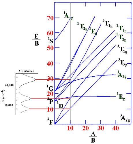
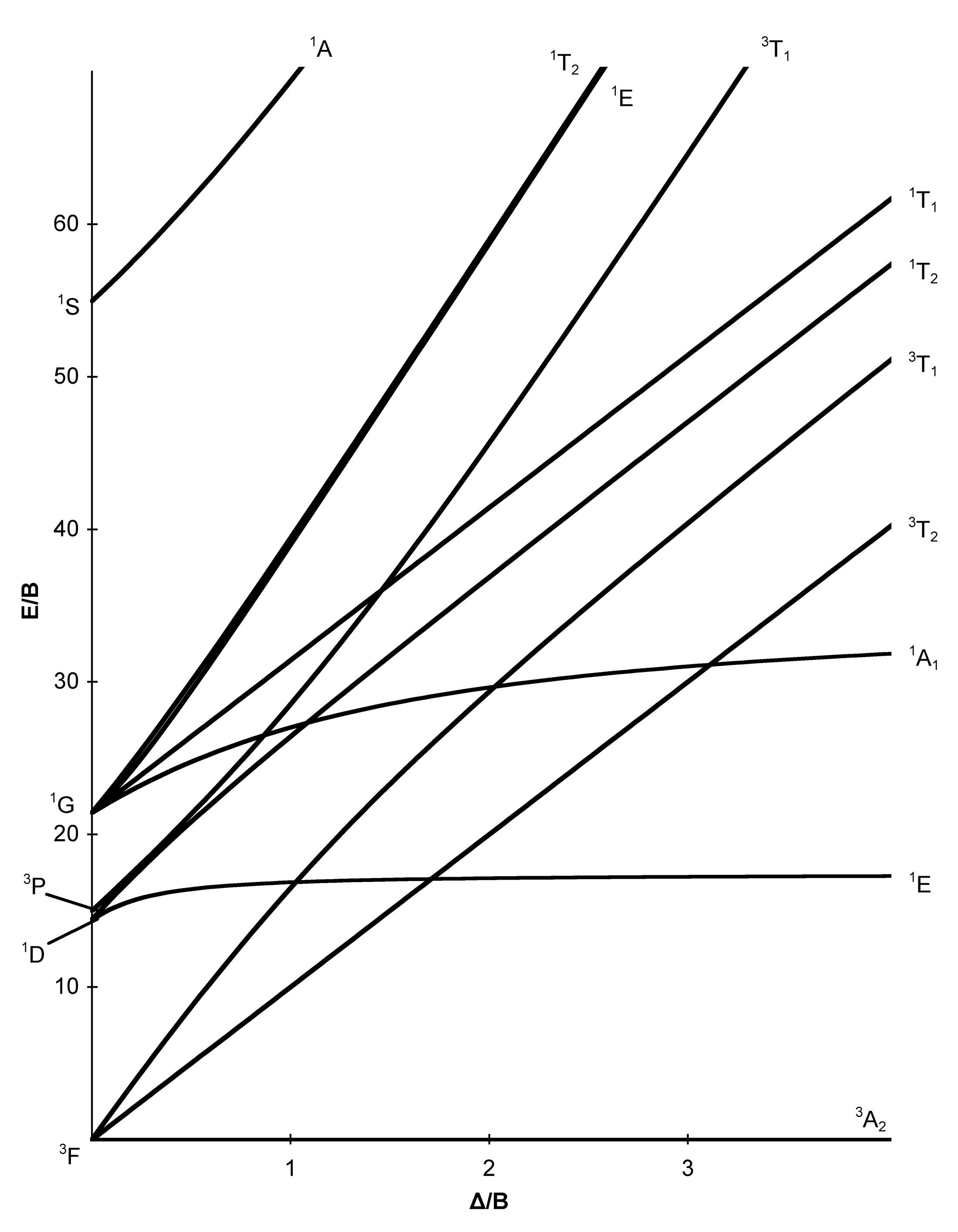
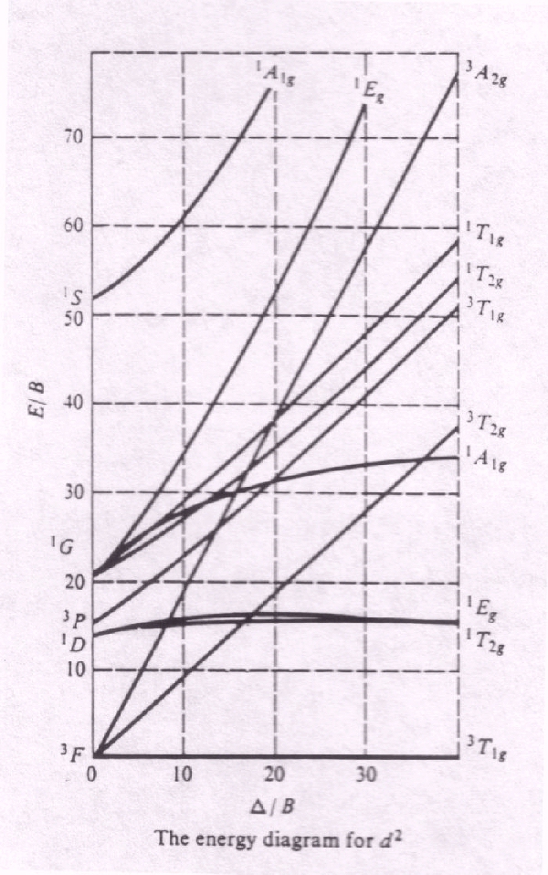
d2 Tanabe-Sugano Diagram 1A 1E 1g g 80 3A 2g 70 60 1T 1g 1T 1S 2g 3T 50 1g E/B 40 3T 2g 1A 1g 30 1G 20 1E 3P g 1D 1T 2g 10 3F 3T 0 1g ∆o/B 0 10 20 30 40 d3 Tanabe-Sugano Diagram 4T 2 1g A2g 80 70 2A 1g 4T 60 1g 50 4T 2g E/B 40 2F 2T 2g 30 2T 1g 20 2E 2G g 4P 10 4F 4A 0 2g ∆o/B 0 10 20 30 40 50 d4 Tanabe-Sugano Diagram 3A 1 2g A2 d2 Tanabe-Sugano diagram. A Tanabe-Sugano diagram of the spin-allowed and some forbidden transitions for octahedral d 2 and tetrahedral d 8 complexes is given below. spin-allowed transitions (Δ/B' > 13.5) Solid lines 3 A 2g (P) ← 3 T 1g Green 3 T 1g (F) ← 3 T 1g Blue 3 T 2g (F) ← 3 T 1g Red Orgel diagrams only show the symmetry states of the highest spin multiplicity instead of all possible terms, unlike a Tanabe-Sugano diagram. Orgel diagrams will, however, show the number of spin allowed transitions, along with their respective symmetry designations. In an Orgel diagram, the parent term (P, D, or F) in the presence of no Tanabe-Sugano Diagrams. Tanabe-Sugano diagrams are used in coordination chemistry to predict electromagnetic absorptions of metal coordination compounds of tetrahedral and octahedral complexes. The analysis derived from the diagrams can also be compared to experimental spectroscopic data. Armed with spectroscopic data, an approximation to the ...
Tanabe Sugano Diagram: Sugano. Read or Downloads . Tanabe Sugano Diagram suganorm suganorm forte suganorm erfahrungen suganorm pzn suganorm apotheke suganorm preis suganorm amazon suganorm kaufen in deutschland suganorm diabetes suganorm inhaltsstoffe suganorm 20 kapseln x 2 suganorm online apotheke tanabe sugano diagram pdf tanabe sugano diagramm tanabe sugano diagramm d5 tanabe sugano ... Tanabe-Sugano diagrams can be used for both high spin and low spin complexes. Tanabe-Sugano diagrams can also be used to predict the size of the ligand field necessary to cause high-spin to low-spin transitions. In a Tanabe-Sugano diagram, the ground state is used as a constant reference. The energy of the ground state is taken to be Notes on d7 Tanabe-Sugano Diagram!The d 7 diagram, like all such diagrams for configurations that may be either high spin or low spin, has a perpendicular line near the middle marking the change in spin state. "To the left of the line (low field strength, high spin), the ground state is 4T 1, emerging from the free-ion 4F term. Title: Microsoft PowerPoint - handout6b Author: Alan Jircitano Created Date: 11/22/2004 11:06:49 PM
Tanabe Sugano diagram untuk kompleks Oh dengan konfigurasi d2 ke d8 diberikan dalam Bagian sumber daya 6 . Nol energi dalam diagram Tanabe ? Sugano selalu diambil sebagai bahwa istilah terendah .
d2 Tanabe-Sugano Diagram. Captions. Summary . Description: English: The Tanabe-Sugano diagram for a d 2 transition metal ion. The energies are calculated using a Racah C = 4.5 B, and only selected states are depicted. Transitions from the triplet ground state to singlet excited states (dotted) are spin-forbidden.
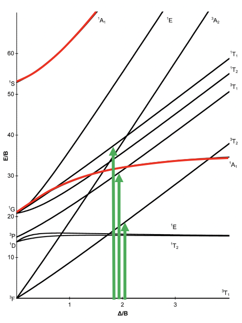
Tanabe-Sugano diagram for d2 octahedral complexes. On moving up the line from the ground term to where lines from the other terms cross it, we are able to identify both the spin-forbidden and spin-allowed transition and hence the total number of transitions that are possible in the electronic spectrum.
d 2 Tanabe-Sugano Diagram. Duda Baif. Download PDF. Download Full PDF Package. This paper. A short summary of this paper. 29 Full PDFs related to this paper. Read Paper. d 2 Tanabe-Sugano Diagram.

There is no low-spin or high-spin designation for d2, d3, or d8 All of prepared Ni(II) complexes are d8 and have 3 d-d transitions Summary Definition of Tanabe-Sugano diagrams How to determine the d-d transition for metal ion Tanabe-Sugano diagrams for HS & LS in Oh geometry References Inorganic chemistry, Shriver and Atkins, fifth edition ...

d2 Tanabe-Sugano Diagram . d5 Tanabe-Sugano Diagram d4 Tanabe-Sugano Diagram . d6 Tanabe-Sugano Diagram . d8 Tanabe-Sugano Diagram . Author: Jircitano, Kellie Created Date: 3/14/2011 4:00:24 PM ...
Tanabe Sugano Exercises These questions deal in part with concepts presented in today's lecture and assigned readings. Have a look at the Tanabe-Sugano diagram for the d 5 case. What is the term symbol for the ground state of a free d 5 ion (where Δ o /B = 0)?; What is the term symbol for the ground state of a d 5 ion satisfying the condition that Δ o /B = 20?; What is the physical meaning ...
Lecture 4 May 11: Tanabe Sugano Diagrams A Tanabe-Sugano (TS) diagram plots the energy dependence of the various ligand field states (or terms) with field strength. The strength of the ligand field is defined by Dq, which is related to the octahedral crystal field splitting by 10Dq = ∆o. The energy of the state is given by E.
T sdiagram. 1. d2 Tanabe-Sugano Diagram 1A 1E 1g g 80 3A 2g 70 60 1T 1g 1T 1S 2g 3T 50 1g E/B 40 3T 2g 1A 1g 30 1G 20 1E 3P g 1D 1T 2g 10 3F 3T 0 1g 0 10 20 30 40 ∆o/B.
d2Tanabe-Sugano Diagram E / B ∆o/ B 3F 3P 3T 1g (3P) 3A 1g 3T 2g (3F) 3T 1g ~15B ~∆o ~∆o E1 E2 E3 E is the energy of the excited state relative to the ground state B is the Racah parameter for e--e-repulsion The example on page 427 of your text shows how to use this chart to fit the experimental data (E1, E2, and E3) for [V(OH2)6]3+to ...

Certain Tanabe-Sugano diagrams (d 4, d 5, d 6, and d 7) also have a vertical line drawn at a specific Dq/B value, which is accompanied by a discontinuity in the slopes of the excited states' energy levels.This pucker in the lines occurs when the identity of the ground state changes, shown in the diagram below. The left depicts the relative energies of the d 7 ion states as functions of ...
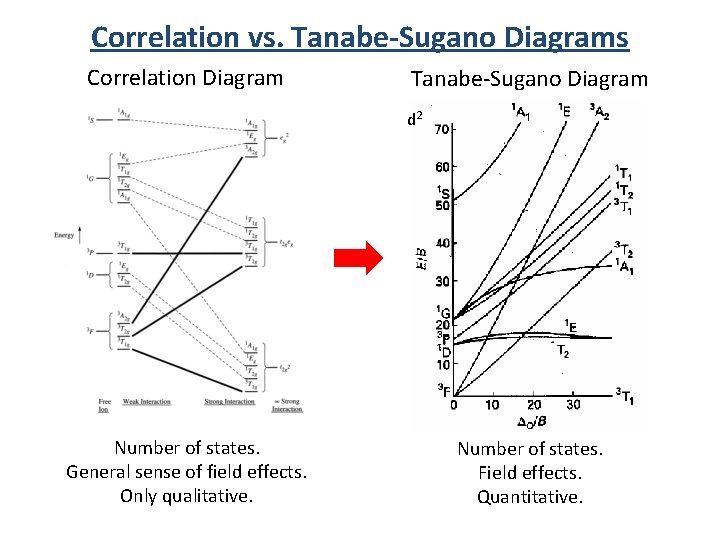
Tanabe-Sugano diagram for d2 octahedral complexes 2/26/2019 12 13. Advantages over Orgel diagrams • Tanabe-Sugano diagrams can be used for both high spin and low spin complexes, unlike Orgel diagrams which apply only to high spin complexes. • In a Tanabe-Sugano diagram, the ground state is used as a constant reference, in contrast to ...
Orgel and Tanabe-Sugano Diagrams for Transition Metal Complexes (d1 - d9 States) It is a well-known fact that electronic transitions are always accompanied by vibrational as well as rotational changes which results in a considerable broadening of the bands in the UV-visible spectra of transition metal complexes too.
Tanabe Sugano Diagram d2 #drbeenakiscience #csir #gate #net


0 Response to "39 d2 tanabe sugano diagram"
Post a Comment