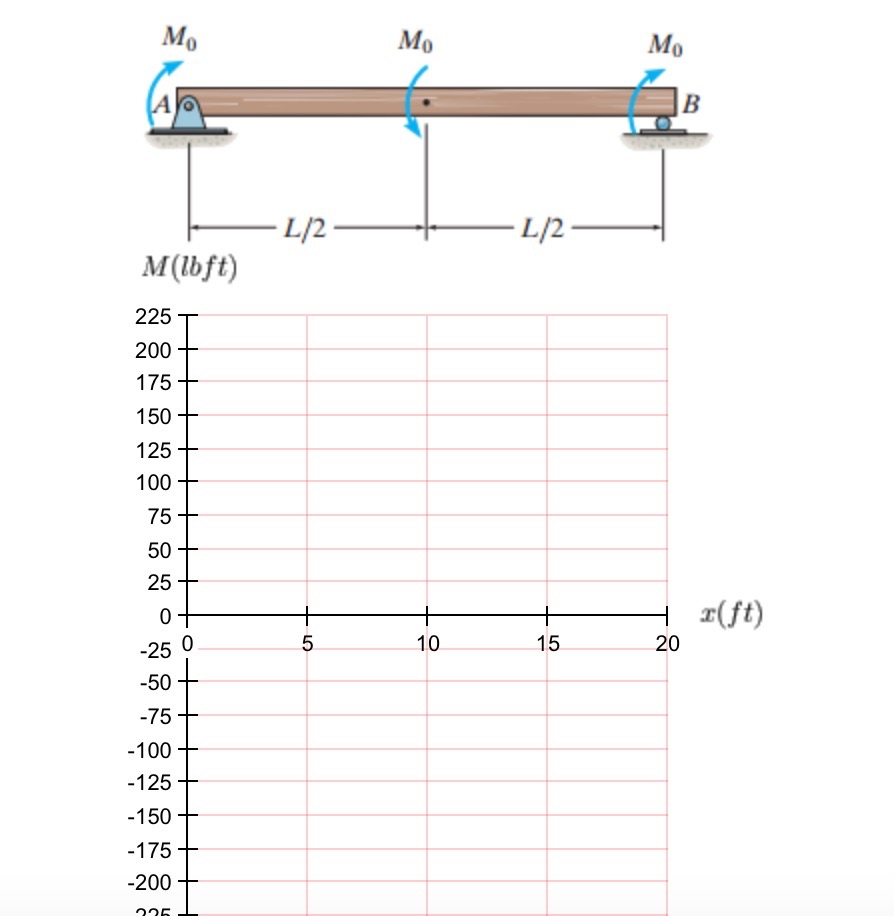
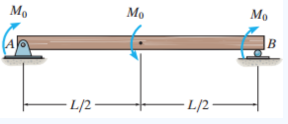
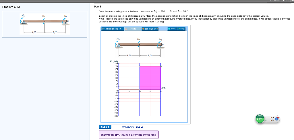
42 draw the shear diagram for the beam. assume that m0=200lb⋅ft, and l=20ft.
Check out http://www.engineer4free.com/structural-analysis for more free structural analysis tutorials. The course covers shear force and bending moment diag... Draw the shear diagram for the beam. Assume that M 0=200lb⋅ft, and L =20ft. Show transcribed image text. Expert Answer. Who are the experts? Experts are tested by Chegg as specialists in their subject area. We review their content and use your feedback to keep the quality high. 100% (4 ratings)
Problem 4.3-1 Calculate the shear force V and bending moment M ... 200 lb/ft. 6 ft ... M0. L. Problem 4.5-3 Draw the shear-force and bending-moment diagrams.26 pages

Draw the shear diagram for the beam. assume that m0=200lb⋅ft, and l=20ft.
Transcribed image text: Problem 6.13 Part A Draw the shear diagram for the beam. Assume that Mo 200 lb.ft, and L 20 ft. Begin by placing the lines of discontinuity. Place the appropriate function between the lines of discontinuity, ensuring the endpoints have the correct values Note Make sure you place only one vertical line at places that require a vertical line. Academia.edu is a platform for academics to share research papers. Problem 6.13 Part A Draw the shear diagram for the beam. Assume that Mo 200 lb.ft, and L 20 ft. Begin by placing the lines of discontinuity.
Draw the shear diagram for the beam. assume that m0=200lb⋅ft, and l=20ft.. Draw the shear diagram for the beam. Assume that M0=200lb⋅ft, and L=20ft. Begin by placing the lines of discontinuity. Place the appropriate function between the lines of discontinuity, ensuring the endpoints have the correct values. Note - Make sure you place only one vertical line at places that require a vertical line. If you. Draw the shear diagram for the beam. Assume that M0=200lb⋅ft, and L=20ft. Begin by placing the lines of discontinuity. Place the appropriate function between the lines of discontinuity, ensuring the endpoints have the correct values. Note - Make sure you place only one vertical line at places that require a vertical line. Draw the shear and moment diagrams for the cantilevered beam. 300 lb. 200 lb/ft. A. 6 ft. The free-body diagram of the beam's left segment sectioned through ...143 pages Assume that Mo = 200 lb-ft, and L-20 ft. Begin by placing the lines of discontinuity Place the appropriate function between the lines of discontinuity, ensuring ...Missing: m0= ⋅
Draw the shear and moment diagrams for the beam and determine the shear and moment as functions of x. 3 m 3 m x AB 200 N/m 400 N/m Ans: M = e - 100 9 x ... the web D of the beam. 15 kip # ft. 3 in. 5 in. 1 in. 1 in. 8 in. M 15 kip ft 1 in. A B D Using flexure formula % of moment carried by web = Ans. 3.3852 15 middot ft, and L = 20 ft. Begin by placing the lines of discontinuity. Place the appropriate function between the lines of discontinuity, ensuring the endpoints ... 4.3 Shear- Moment Equations and Shear-Moment Diagrams The determination of the internal force system acting at a given section of a beam : draw a free-body diagram that expose these forces and then compute the forces using equilibrium equations. The goal of the beam analysis -determine the shear force V and Draw the shear diagram for the beam. Assume that w 0 | Chegg.com. Engineering. Mechanical Engineering. Mechanical Engineering questions and answers. Draw the shear diagram for the beam. Assume that w 0 =10kip/ft , and L=18ft Draw the moment diagram for the. Question: Draw the shear diagram for the beam. Assume that w 0 =10kip/ft , and L=18ft ...
Knowing that for each cable TA = 3100 N and TB = 3300 N, determine (a) the angular acceleration of the roll, (b) the acceleration of its mass center. SOLUTION Data: m = 1200 kg I = mk 2 = (1200) (0.150) 2 = 27 kg ⋅ m 2 1 1 r = d = (0.100) = 0.050 m 2 2 TA = 3100 N TB = 3300 N (a) Angular acceleration. Problem 6.13 Part A Draw the shear diagram for the beam. Assume that Mo 200 lb.ft, and L 20 ft. Begin by placing the lines of discontinuity. Academia.edu is a platform for academics to share research papers. Transcribed image text: Problem 6.13 Part A Draw the shear diagram for the beam. Assume that Mo 200 lb.ft, and L 20 ft. Begin by placing the lines of discontinuity. Place the appropriate function between the lines of discontinuity, ensuring the endpoints have the correct values Note Make sure you place only one vertical line at places that require a vertical line.









0 Response to "42 draw the shear diagram for the beam. assume that m0=200lb⋅ft, and l=20ft."
Post a Comment