42 radiant heat mixing valve diagram
Three-way Mixing Valve Installation Guide 1 Introduction The Uponor Three-way Mixing Valve (A3040075, A3040100) is a microprocessor-controlled valve designed to regulate the supply water temperature to a radiant heating system by modulating the position of the valve. Mixed supply setpoint can be configured to reset from the outdoor air temperature. Taco Mixing Valves 5000 Series, Taco Thermostatic Mixing Valve 2-Way I Series. Taco Mixing Valve 3-Way Indoor Outdoor Reset Mixing Valves. Used for Hydronic Heating Systems such as Radiant Floor Heating and Domestic Hot Water. All Sharkbite Fittings Discounted as Priced - Limited Supplies. Free Shipping on Orders Over $200*
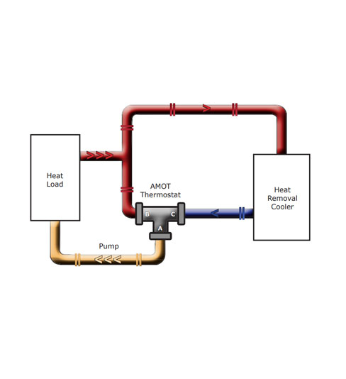
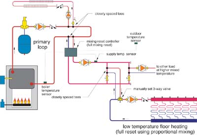
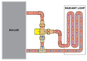
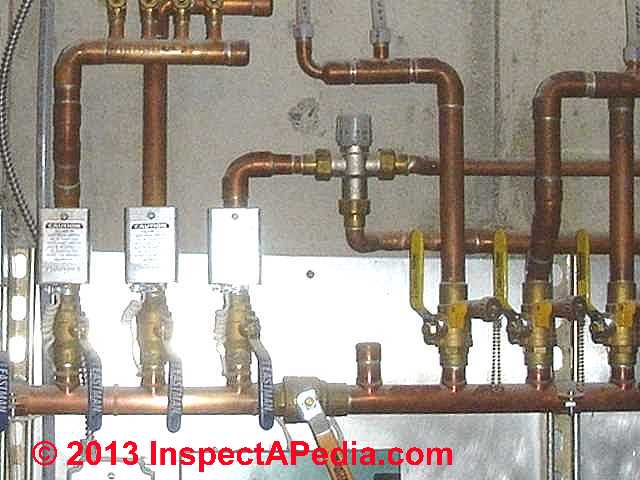
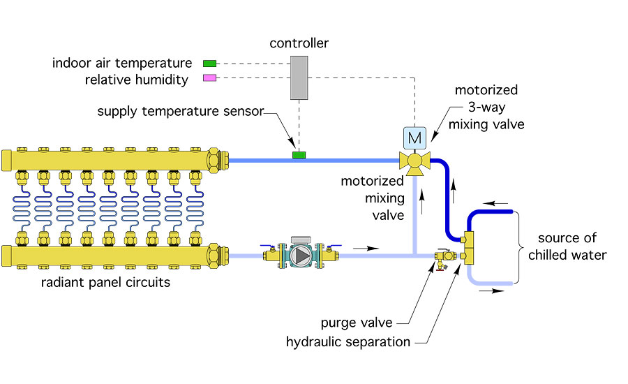
Radiant heat mixing valve diagram. The much cooler radiant floor zones receive tempered water from the mix port of the mixing valve. The baseboard or cast iron radiator zones for example receive super hot water straight from the heat source. Mixed supply setpoint can be configured to reset from the outdoor air temperature.

Radiant heat mixing valve diagram
Title: 2.3 2/3/4 Way Mixing (OM03) Author: Graphic Images, Inc. Created Date: 9/2/2005 4:38:22 PM The first part contains a general overview of radiant heat and it's various applications. All the necessary components of a well-engineered and efficient hydronic radiant floor system are explained in a straight forward and non-technical manner. The second section gets down to the nitty gritty details of ... Mixing Valve Secondary loop In. 50 ... On the supply side of the radiant coming out of the 4 way mixing valve, you would have a 2nd pump to pull heat out and push it into the radiant piping (a fixed speed pump like a grundfos 15-18, probably on low or medium speed would fit the bill here as you don't have much radiant to worry about).
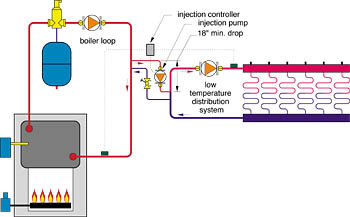
Radiant heat mixing valve diagram. A mixing valve is pre-installed in this type of manifold. The baseboard or cast iron radiator zones, for example, receive super hot water straight from the heat source. The much cooler radiant floor zones receive tempered water from the "mix" port of the mixing valve. The schematic below illustrates this approach. Piping layouts to avoid in hydronic systems. Einstein's definition of insanity was doing the same thing over and over and expecting different results. If that is true, there are some "insane" hydronic system designers in North America. They repeatedly cling to certain system piping configurations, even though existing projects using those ... Radiant Heating 101: Mixing valves and controls for in-floor radiant heating A solid control apparatus is the cornerstone of a well-designed in-floor radiant heating system. The chief function of a control system is to modulate and limit water-temperatures to maximize efficiency and to insure against over-heated floors. Mixing Methods with Radiant Heating Systems ... Two ports go to the boiler and two ports go to the radiant zone. This valve can be set manually or used with an actuator to modulate the water temperature based on the zone load. 4. The last method is with an injection pump. This method has been used since the early 1960s.
Thermostatic mixing valve. 25-50°C 40-70°C 167 series Code: 167032 167042 Technical Brochure: 01239 Three-way valve with sector obturator and three point actuator. RH LH 165 series Code: 165001 Mounting bracket in stainless steel. 519 series Code: 519006 Technical Brochure: 01237 Differential by-pass valve, setting range 0,2-3 m w.g.. Thermostatic mixing valves are used in residential, commercial and institutional applications for both plumbing and hydronic heating. The primary function of these valves is to control the output water temperature to either a domestic hot water supply system, or provide a low temperature supply to a radiant floor heating system. This is especially true when the valve is used to mix high temperature boiler water to a substantially lower temperature for a radiant floor heating system. In such systems, the amount of hot water required in the mix is usually only of 15 to 20% of the flow rate in the distribution system. Tips for properly installing these mixing valves in radiant heating systems. One of the best known temperature control devices in hydronic radiant heating systems is the three-way thermostatic mixing valve. It's available from several manufacturers with either an internal thermostatic element or an external actuator.
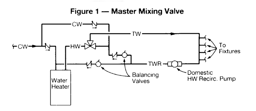
My question is related to this topic and it is about the following code: "607.2.2 Piping for Recirculation Systems Having Master Thermostatic Valves: Where a thermostatic mixing valve is used in a system with a hot water recirculating pump, the hot water or tempered water return line shall be routed to the cold water inlet pipe of the water heater and the cold water inlet pipe or the hot water ... • Assemble the actuator/motor and the valve. Then wire the Actuator to the heating control. 3-Way Motorized Valve Overview The 3-Way Motorized Valve can be used in a variety of applications. This manual will describe its use in heating applications only. Mixing In radiant applications, 3-way motorized valves can be used to mix the hot water ... Variable Speed Injection Mixing uses a circulator as a mixing device instead of a 2-way,3-way or 4-way valve.Typically used in radiant primary/secondary piping designs, the variable speed pump is installed in the "bridge" piping (see Figure 1) Mixing Valve DHW Circulator w/Aquastat&Check Valve Backflow Preventor Air Elimination NCB-240E ASME Gas H Heating Domestic S R C NCB-210E ASME Gas H Heating Domestic S R C NCB-180E ASME Gas H Heating Domestic S R C Gas H Heating Domestic S R C NCB-150E ASME. 20 Goodyear Irvine, CA 92618 800-519-8794 www.navien.com T Check Valve Circulator Drawn ...
Watts Radiant hydronic MixTemp valves are most commonly used in lower. temperature to a radiant heating system by modulating the position of the valve. Figure 2: Three-way Mixing Valve Typical Piping Diagram. Flow. GPM.Mixing valves mix cold and hot water to a desired temperature for a large variety of radiant heating and domestic water ...
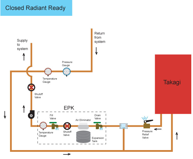
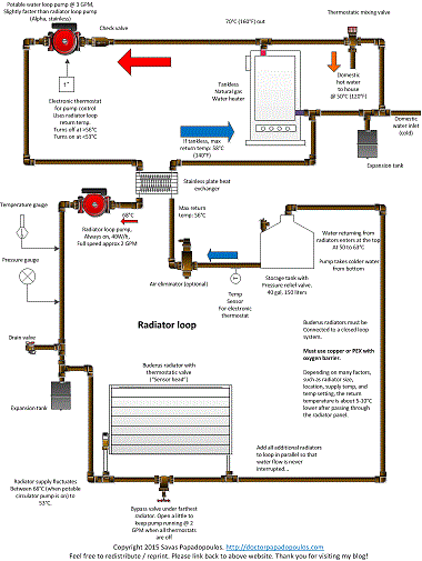
28 Radiant Heat Mixing Valve Diagram Wiring Diagram List. Click Images to Large View 28 Radiant Heat Mixing Valve Diagram Wiring Diagram List. Radiant Heat Mixing Valve Diagram. Click Images to Large View Radiant Heat Mixing Valve Diagram. Hot Water Radiant Floor Piping — Heating Help The Wall.
Now consider that mixing valve used to control the temperature being fed to -- let's say a radiant loop. The hot inlet is connected to a manifold or to a boiler. The cold inlet is connected to the return from the loop through a T. How do we get it so that the outlet has a lower pressure? Well, on the hot side that shouldn't be a problem.
Gonna be replacing this system and I have installed 3 way mixing valves but never a 4 way. Im trying to figure out this layout. Is it fair to say the supply and return is the primary and the other side of the mixing would be secondary? also it looks to be the radiant pump is returning into the mixing valve.Diagrams ive looked up show that the top should be the output.

Renewable Hydronic Heating Home Power Magazine Heating Systems Floor Heating Systems Hydronic Heating Systems
Thermostatic Mixing Valves are for controlling water temperatures in PEX radiant floor heat, Solar Hot Water Heating and other hydronic applications. Taco Power Mixing Valves are also for solar hot water tanks when needed to reduce water temperature to safe levels for home use.
In this excerpt from his Classic Hydronics seminar, Dan Holohan shares his knowledge about mixing low-temperature radiant heating with a higher-temperature h...
INFLOOR HEATING SYSTEM oor® Heating Systems er the customer and dealer various options when selecting a radiant heating system . I oor's Residential / Light Commercial Systems include copper manifolds, brass manifolds, mixing valves and related controls, zoning cotrnols with domestic hot water priority, pre-piped and
Heat Exchanger Thermostatic Mixing Valve A pump must be installed in the hot supply line between the outdoor furnace and thermostatic valve. Hot Supply from Pump ... System Diagrams Radiant Heat Multi Zone In-Floor 71 73 75 80 86 102 76 67 65 Forced Air vs. Radiant In-Floor Insulation Closed-cell Polystyrene Thermal Insulation OUT IN
Shop our products: https://pexuniverse.comAbout PEX Universe:PEX Universe (aka PEX-U) is a leading industrial equipment supplier offering high quality heatin...
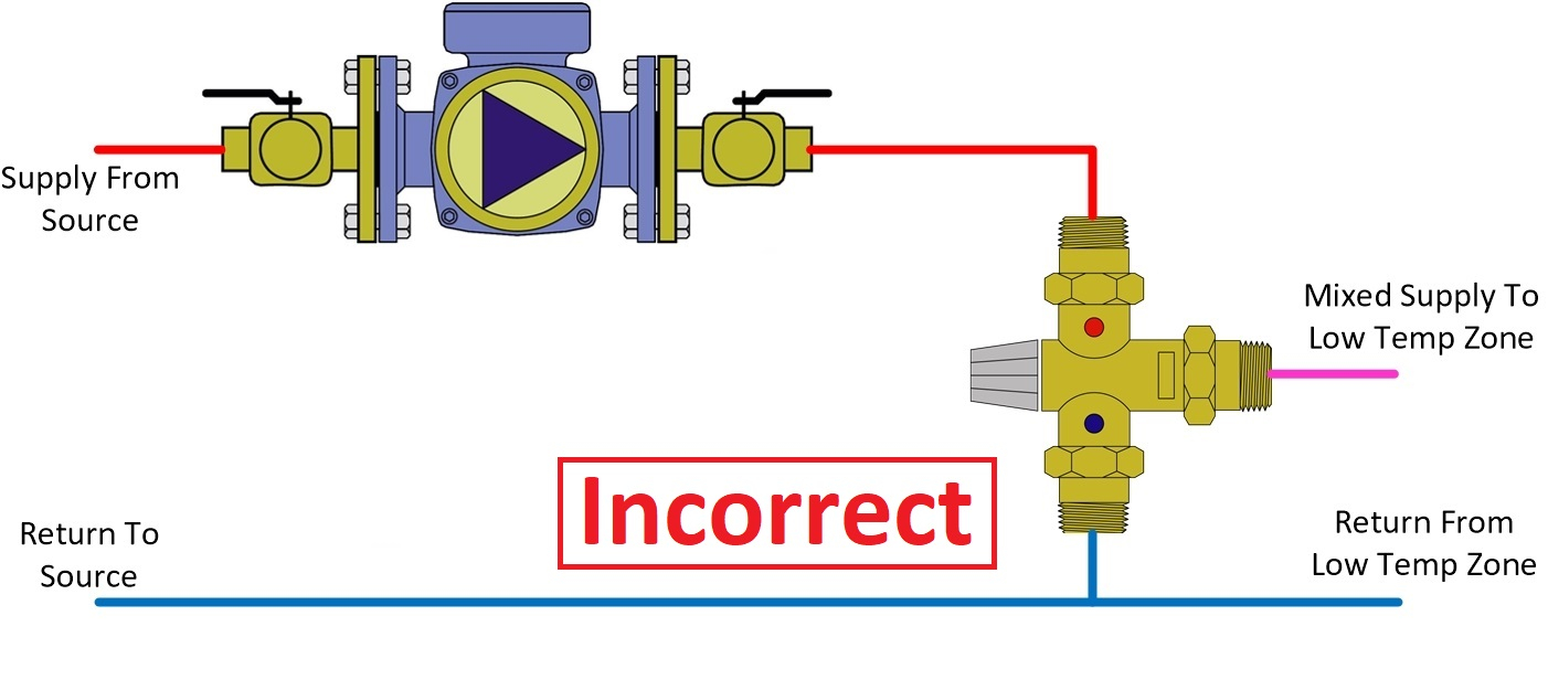
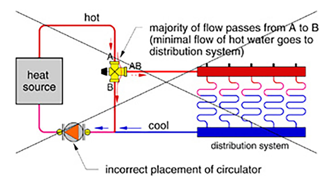
Radiant Heat Mixing Valve Diagram. Piping Schematic. Level I Control. • Modulating-condensing boiler. • Dual- temperature radiant floor heating. • Three-way tempering valve. Where: Multiple. Best practice is to pump away from the mixing valve, not into it. We sometimes hear about a pump discharge being piped to the hot inlet of a ...
Ordering Code: 722. UPC: 779655072201. 4-Way Mixing Valve, 1 1/4 IN Brass. The 4-Way Brass Mixing Valve 722 is used to mix supply water from a hydronic source with water returning from a system. It is designed for use in either closed loop or open loop hydronic systems. This 4-way valve has standard female NPT threads, as well as a maximum leak ...
On the supply side of the radiant coming out of the 4 way mixing valve, you would have a 2nd pump to pull heat out and push it into the radiant piping (a fixed speed pump like a grundfos 15-18, probably on low or medium speed would fit the bill here as you don't have much radiant to worry about).
The first part contains a general overview of radiant heat and it's various applications. All the necessary components of a well-engineered and efficient hydronic radiant floor system are explained in a straight forward and non-technical manner. The second section gets down to the nitty gritty details of ... Mixing Valve Secondary loop In. 50 ...
Title: 2.3 2/3/4 Way Mixing (OM03) Author: Graphic Images, Inc. Created Date: 9/2/2005 4:38:22 PM

Hydronic Heating Trim Heating Supplies For Hydronic Boilers Hydronic Heating Hydronic Radiant Floor Heating Floor Heating Systems















0 Response to "42 radiant heat mixing valve diagram"
Post a Comment