36 fe cr phase diagram
C Equilibrium Phase Diagram. 20 um Fe - 0.003% C, diagram and microstructure (2% nital). ... (Fe < 0.08% C - 17% Cr - 12% Ni - 2.5% Mo) after hot acid etching. Disc cut transverse to the growth direction (strand axis). There is a very thin surface layer of equiaxed grains and the columnar grains go to the center. There is no central ...
The microstructure of the investigated alloy is composed of primary and secondary dendrites Fe-Cr solid solution and complex M Cr-C phase diagram [9] A Fe-Cr-C ingot with the cross section line...
ternary phase diagram of Ni-Cr-Fe. MSE 2090: Introduction to Materials Science Chapter 9, Phase Diagrams 11 Isomorphous system - complete solid solubility of the two components (both in the liquid and solid phases). Binary Isomorphous Systems (I) Three phase region can be identified on the phase diagram:

Fe cr phase diagram
the ternary phase diagram with respect to the aus-tenite stabilized region in the low Cr composition has not beenentirely identified evenin the recent st.udy. Thepurpose of this study is to investigate the eq,ui-librium phasediagram of Fe-Cr-Mnsystem at 923 K (650'C), in particular, to examine the extent of a single phase reg_ion in the low Cr ...
1273K-C-Cr-Fe FSstel: 1273K-C-Fe-Mn FSstel: Ag-Al FScopp: Ag-Al FTlite: Ag-Al SGnobl: Ag-Al SGTE 2014: Ag-Al SGTE 2017: Ag-Al SGTE 2020: Ag-Al-Au_500C SGnobl: Ag-Al-Bi_870C SGnobl: Ag-Al-In_650C SGnobl: Ag-Al-Mg_liquidus SGnobl: Ag-Al-Pb_870C SGnobl: Ag-Al-Si_500C SGnobl: Ag-Al-Si_liquidus SGnobl. Ag-Al-Sn_25C SGnobl: Ag-Al-Sn_liquidus SGnobl ...
binary and ternary phase diagrams of Al(acac) 3-Cr(acac), Cr(acac) 3-Fe(acac) 3, Al(acac) 3-Fe(acac) 3 and Al(acac) 3-Cr(acac) 3-Fe (acac) 3 were constructed and their eutectic temperatures were determined. The eutectic temperature was obtained at 1: 1 ratio for its binary systems. From the binary phase diagram, ternary phase diagram was ...
Fe cr phase diagram.
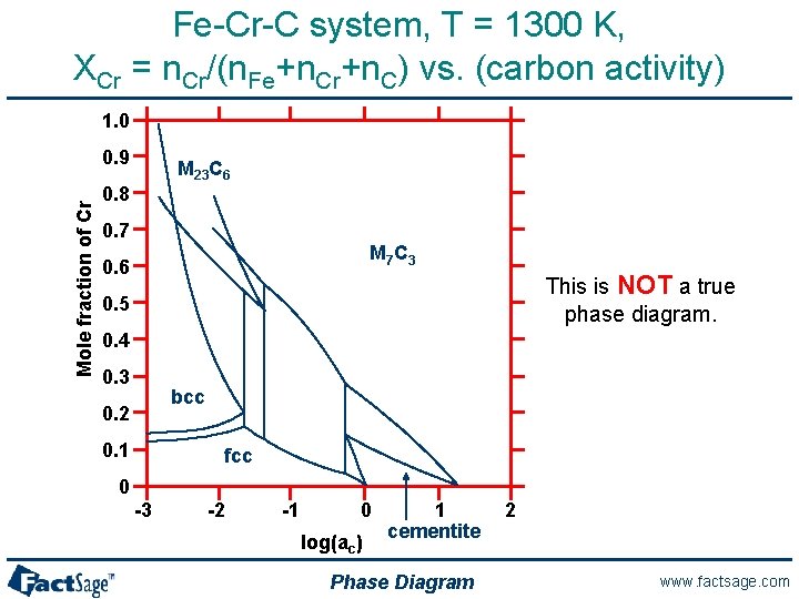
It is evident from Figure 6 (Fe-Cr-C phase diagram) that typical martensitic steels should exhibit ferrite and M 23C 6in equilibrium at for example, 600°C. In practice, this carbide is only found after relatively long ageing. because it is preceded by Intermediate phases in the sequence cementite, M 2X and M 7C 3, leading finally to M 23C 6.
Cr Si Mn W Mo Review Fe-C phase diagram • 2 important points-Eutectoid (B): γ⇒α+Fe 3C-Eutectic (A): L ⇒γ+Fe 3C Fe 3 C (cementite) 1600 1400 1200 1000 800 600 400 0 12 3 4 5 66.7 L γ (austenite) γ+L γ+Fe 3C α+Fe 3C α + γ L+Fe 3C δ (Fe) C o, wt% C 1148°C T(°C) α 727°C = Teutectoid A R S 4.30 Result: Pearlite = alternating ...
192 / Phase Diagrams—Understanding the Basics. A hypothetical ternary phase space diagram made up of metals . A, B, and . C. is shown in Fig. 10.2. This diagram contains two binary eutectics on the two visible faces of the diagram, and a third binary eutectic between ele-ments . B. and . C. hidden on the back of the plot. Because it is ...
Phase diagram of Fe--Cr--Co permanent magnet system Abstract The miscibility gap of the ..cap alpha.. phase in Fe-Cr-Co permanent magnet alloys is constructed using mechanical hardness and Curie temperature measurements.
3) Isothermal phase diagram of Fe-Cr-O system at 1 600°C was established. The relationshp between the chromium content of Fe-Cr melt and the oxide phase equilibrated was determined. below 1% Cr-cubic chromite, 1-7%Cr-c/a=1-0.95 above 7% Cr-Cr2O3
[Show full abstract] Some sections in the phase diagrams of the Cr-Mn-C and Fe-Cr-Mn-C systems and partitioning of alloying elements between solid solution and carbide phases were calculated and ...
The graph is quite complex but since we are limiting our exploration to Fe3C, we will only be focusing up to 6.67 weight percent of carbon. This iron carbon phase diagram is plotted with the carbon concentrations by weight on the X-axis and the temperature scale on the Y-axis. Iron crystal structures explained
The phase diagram of the Ti-Fe-Cr ternary system is fundamental to developing novel alloys containing the elements. Some high hydrogen storage capacity alloys are based on the Ti-Fe-Cr system, it was demonstrated that Fe can partially substitute V and in this way the cyclic durability of alloys will be improved [1], [2], [3].
Phase diagrams at intermediate temperatures are critical both for alloy design and for improving the reliability of thermodynamic databases. There is a significant shortage of experimental data for phase diagrams at the intermediate temperatures which are defined as around half of the homologous melting point (in Kelvin). The goal of this study is to test a novel dual-anneal diffusion multiple ...
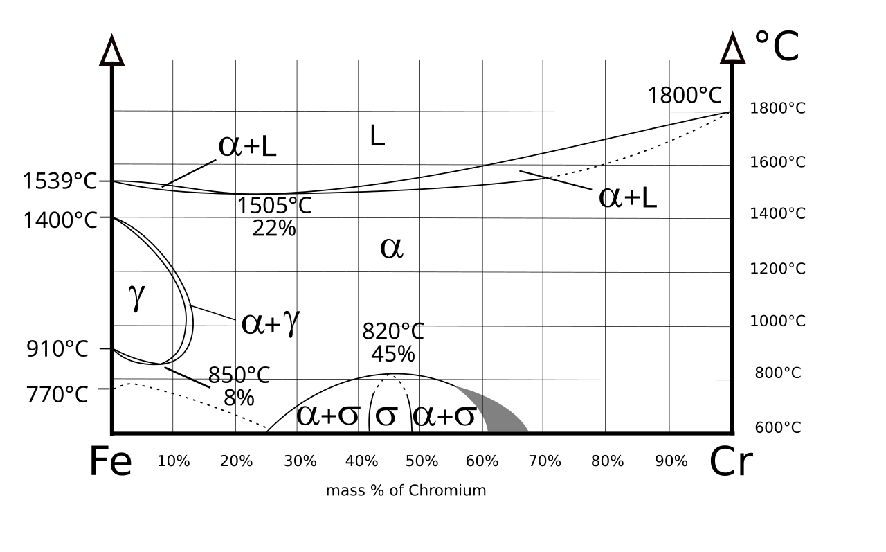
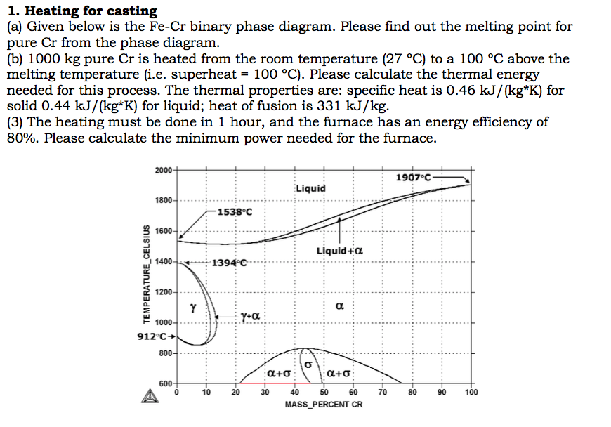
The phase diagram of the Fe-Cr binary system is at Fig 1. The melting point of Fe and Cr is taken at the pressure of 1 atmosphere as 1538 deg C and 1907 deg C respectively. The sigma phase, which is an intermetallic FeCr compound, can sometimes form in Fe-Cr alloys, such as AISI 316 or AISI 310 stainless steels.
The re-calculated phase diagram of the Fe-Cr system based on the present study is shown in Fig. 1. As expected, the FCC γ-loop is observed on the Fe-rich side. The BCC phase has a large miscibility gap between Fe-rich (BCC) and Cr-rich (BCC') alloy compounds. σ phase is stable at elevated temperatures. Download : Download high-res image (105KB)
Fe + Cr Nb + MO + Si Figure 3. Psuedo-Equilibrium Ternary Solidification Diagram for A718 Showing Solidification Path Direction from y to y t A,B Laves Phase (After Reference 5) Figure 3 also indicates that higher levels of Nb, MO, and Si promote the formation of Laves phase.

Cr-fe phase diagram and database (gedb for factsage)
Methods The Fe-Cr-Al phase diagrams and elastic properties are investigated in the following way. The first-principles calculations give the stable phases and elastic properties at zero temperature. Then the results are extended to finite temperature by means of the cluster variation method (CVM) [30,31] and cluster expansion method(CEM) [32].

File:fe cr phase diagram.svg - wikipedia
For "normal diagrams", where interested in all . components, use the . Normal equilateral . triangle. For diagrams where there is a major . component, e.g. Fe in Fe-C-Cr, use a . right-angled triangle →
Fe-cr binary phase diagram adapted from massalski see ref. 7 ...
English: The different version of File:Diagramme phase Fe Cr.svg.The horizontal axis label has been changed to English, and the blank space has been reduced. According to the description of File:Diagramme phase Fe Cr.svg, this diagram was made based on the source "Phase diagramme iron-chromium as per BAIN and ABORN - Metals handbook, American Society for Metals, 1948, 1194".
.png)
Fe-cr-c (1000 k) | japan atomic energy agency
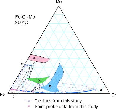
The Fe-Cr-Mo phase diagram contains two solid solutions (bcc (α) and fcc (γ)), four binary intermetallic compounds/phases (the σ, μ, λ (the Laves phase) and R phases), and one ternary phase (the χ (Chi) phase which was denoted as τ 1 in the early literature and in Ref 5 ).
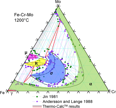
Determination of the fe-cr-mo phase diagram at intermediate ...
Transmission electron microscopy and the corresponding selected-area electron diffraction patterns of Fe-(10;20;30;40;47) wt. pct. Cr alloys heat treated isothermally from 500°C up to 1500°C at 100°C was employed to construct the equilibrium Fe-rich portion of the Fe-Cr phase diagram. It has been found to be quite different from the generally accepted one. Two regions of phase separation ...
Ternary phase diagram overview
The Ti-Si-N-O quaternary phase diagram • Entire phase diagram can be calculated by taking into account all possible combinations of reactions and products • 4 ternary diagrams of Ti-Si-N, Ti-N-O, Ti-Si-O and Si-N-O were evaluated • additional quaternary tie lines from TiN to SiO 2 and Si 2N 2O A.S.Bhansali, et al., J.Appl.Phys. 68(3 ...
Determination of the fe-cr-mo phase diagram at intermediate ...
-4-)Two-component or Binary phase diagrams: Temperature-composition diagram, P constant Composition (concentration): Mole or mass fraction (or percent) of a constituent i in a given alloy - Liquidus: the line above which the alloy is properly in a liquid (L) state -Solidus: the line below which the alloy is properly in a solid (α) state-Solvus: the line which represents the limit of solid ...

Local thermal processing effects in the morphological ...
In the present evaluation, the assessed stable Fe-C (graphite) and metastable Fe-Fe3C (cementite) equilibrium phase diagrams for 0 to 25 at.% C are based on thermodynamic calculations reported by [79Schl] and [84Oht].

File:fe-cr phase diagram.gif - wikiversity
No phase diagram was found for the Fe-Cr-N pp. 4101-07. 3. High-Nitrogen Steel-88, Conf. Proc., Lille, France, May 18-20, 1988, system at 1173 K for high nitrogen contents as those attained J. Foct and A. Hendry, eds. The Institute of Metals, London, 1989. in this research work. Hence, considering the reported iso- 4. ...
File:phase diagram of fe-cr.svg - wikimedia commons
Description. Phase diagram of Fe-Cr-.2%C.svg. English: Isopleth of ternary phase diagram of Fe-Cr-C at a constant 0.2 % C. The horizontal axis is mass percentage of Cr. This diagram was made by the uploader based on the figure in the following secondary source: 田中 良平(編). 2010『ステンレス鋼の選び方・使い方』改訂 ...

File:phase diagram of fe-cr-0.2%c.svg - wikimedia commons
Phase diagrams for FE-CR-NI based alloys. Part 1: Phase diagrams for binary and ternary alloys of FE, CR and NI with C and with SI. EU publications. Download Order.

Phase diagram of the ag2se – as2se3 system and crystal structure ...
Solved (a) given below is the fe-cr binary phase diagram. | chegg.com

Revised thermodynamic description of the fe-cr system based on an ...

Austenitic steels :: total materia article

The fe-cr phase diagram ͑ ref. 20 ͒ . note that the phase diagram ...
Short-term mechanical properties of fe-cr-al-si alloys | kne ...
1: fe-cr phase diagram (a) [18]; fe-cr-0.1c phase diagram (b) [19 ...

Austenitic steels :: total materia article

A thermodynamic evaluation of the fe–cr–c system - sciencedirect

File:phase diagram of fe-cr-0.2%c.svg - wikimedia commons

Figure 10 from a thermodynamic analysis of the system fe-cr-ni-c-o ...

Phase diagrams and elastic properties of the fe-cr-al alloys: a ...
Metals | free full-text | study on σ phase in fe–al–cr alloys | html

Fe-cr binary phase diagram adapted from massalski see ref. 7 ...
General phase diagram sections arthur d pelton centre

Ferritic stainless steel - wikiwand
Experimental investigation of the phase relationship of the fe-cr ...

Figure 4 | precipitation of phase using general diffusion equation ...
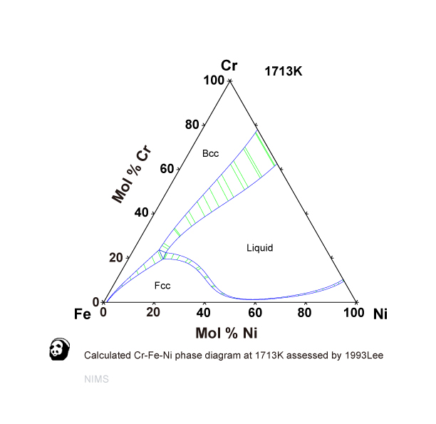
Cr-fe-ni nims)

File:fe-cr-ni-solidus-phase-diagram.svg - wikimedia commons
![Binary iron-chromium equilibrium phase diagram [15], [18 ...](https://www.researchgate.net/profile/Mohammad-Alam-63/publication/315655489/figure/fig2/AS:535998077849606@1504803308716/Binary-iron-chromium-equilibrium-phase-diagram-15-18.png)
Binary iron-chromium equilibrium phase diagram [15], [18 ...

Ni laboratory
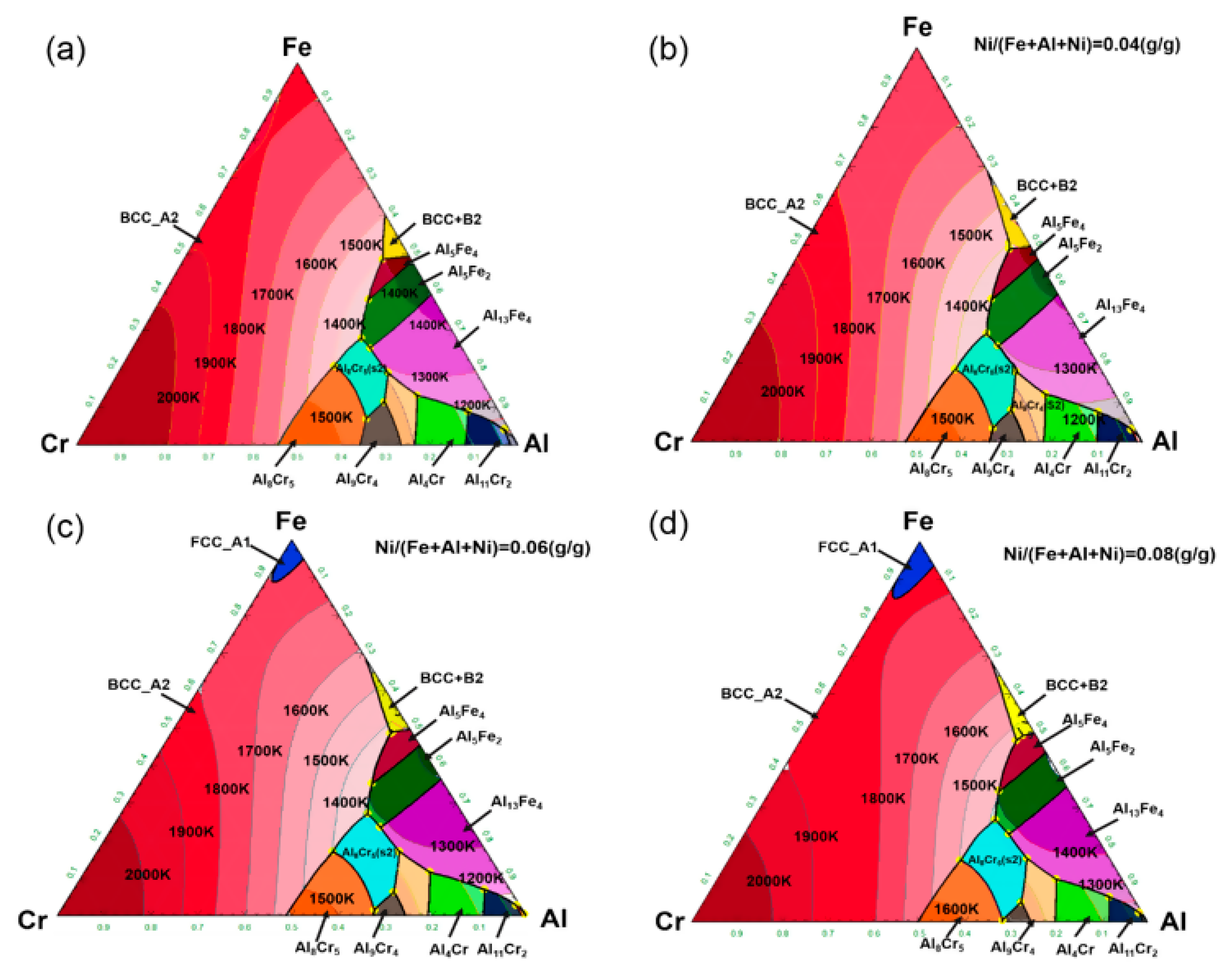
Metals | free full-text | study on σ phase in fe–al–cr alloys | html
Apa yang dimaksud dengan fase terner dan diagram fase terner? - quora
0 Response to "36 fe cr phase diagram"
Post a Comment