37 spectrum analyzer block diagram
Spectrum Analyzer with Block Diagram. A Spectrum Analyzer is a frequency selective voltage indicator. That is it indicates the magnitude of the input signal in the frequency domain. The voltage indicator incorporated in a spectrum analyzer is a Cathode Ray Tube. Therefore we can say that a spectrum analyzer is a special purpose cathode ray ... In this video, i have explained Spectrum Analyzer block Diagram, Basics and Working with following outlines.1. Spectrum Analyzer basics2. Spectrum Analyzer B...
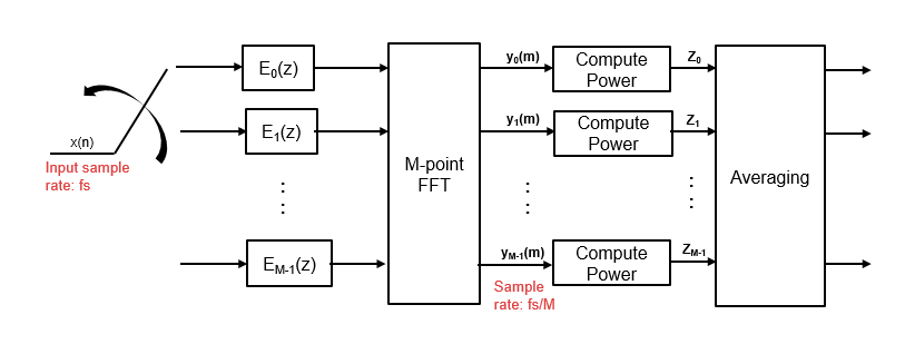
The FFT spectrum analyzer can be considered to comprise of a number of circuit different blocks: FFT Spectrum Analyser Block Diagram. Analogue front end attenuators / gain: The test instrument requires stages at the input of the FFT analyser to ensure that the signal is at the required level for the analogue to digital conversion. These stages ...

Spectrum analyzer block diagram
Simple Spectrum Analyzer Adaptor For Scopes Circuit Under Meters Circuits 14884 Next Gr. An Inexpensive Spectrum Analyzer For The Radio. Audio Spectrum Analyzer Easyeda. Block Diagram For Spectrum Analyzer Scientific. A Working Sprectrum Analyzer Schematic All About Circuits. Agilent Technologies 8 Hints For Spectrum Analysis. Graphical block diagram environment improves productivity when working with complex analysis systems Custom tools and workspaces can be created and later reused or exchanged with other SIGVIEW users Various command-line options for automation and remote control from external applications or from simple batch files function of frequency. Unlike wave analyzers. spectrum analyzers provide a graphical display on a CRT. A block diagram of an audio spectrum analyzer.20 pages
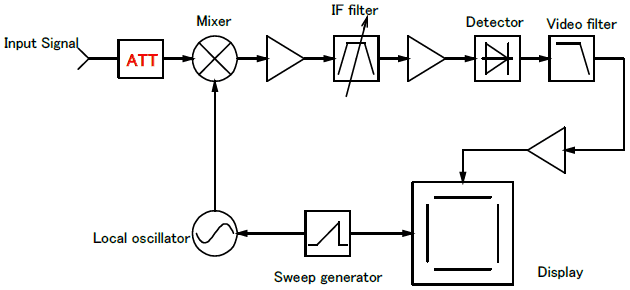
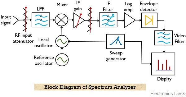
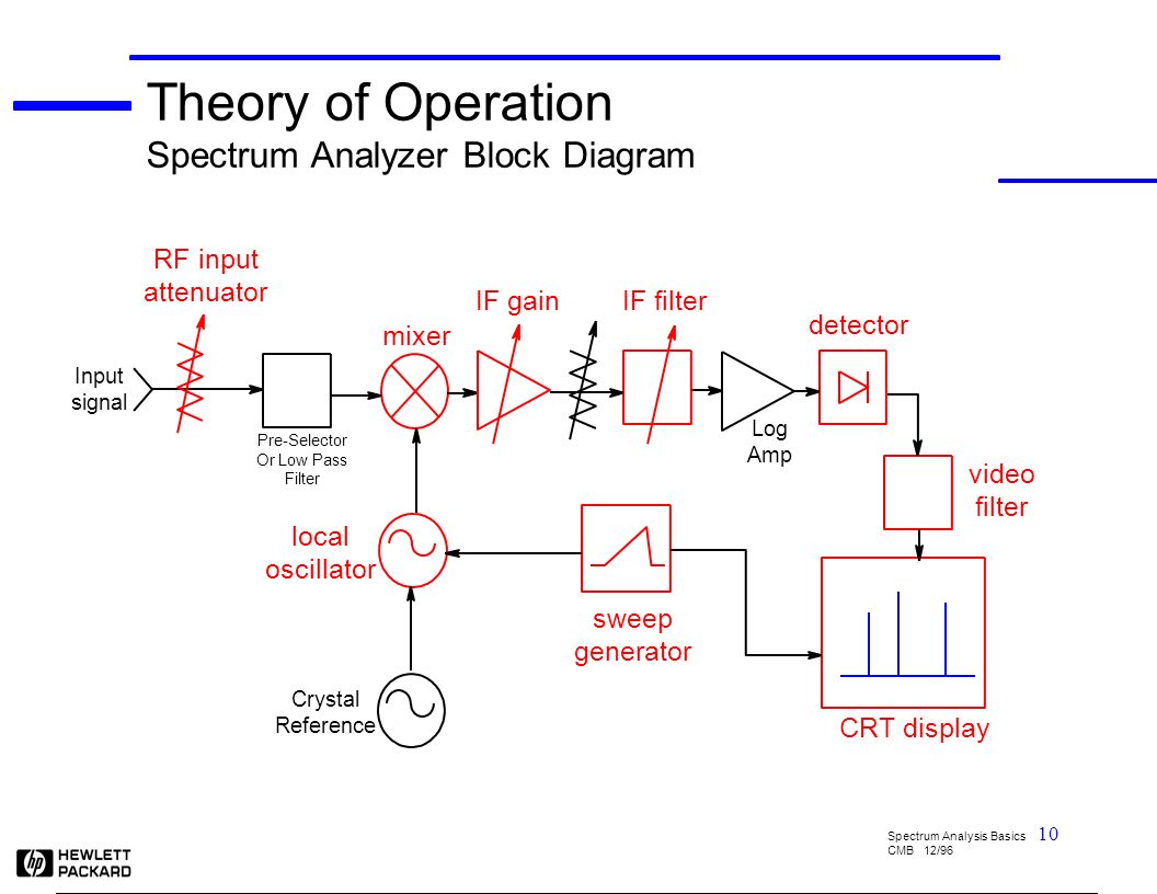
Spectrum analyzer block diagram. The figure-2 depicts simple block diagram of Optical Spectrum Analyzer . Let us understand functions of each of the modules of OSA. • Incoming optical signal to be measured is passed through wavelength tunable filter. This optical filter resolves different spectral components individually. • Photodetector converts optical signal into ... MS2711 Spectrum Analyzer Block Diagram. 13. Press the RBW soft key and use the Up/down arrow key to select 10 kHz. Press ENTER to set the resolution band-width to 10 kHz. 14. Press the VBW soft key and use the Up/down arrow key to select 3 kHz. Press ENTER to set the video bandwidth to 3 kHz. 15. The spectrum analyzer is supplied with the latest version of the RTSA-Suite PRO software. It is the most powerful and versatile spectrum analysis software solution on the market. The RTSA-Suite PRO allows signals to be displayed and analyzed in real time in many different ways. The software is constantly being developed and expanded. Spectrum Analyzer Block Diagram 15. Major blocks in a spectrum analyzer are:- 1] RF input attenuator, 2] Mixer, 3] IF (Intermediate Frequency) gain, 4] IF filter, 5] Detector, 6] Video filter, 7] Local oscillator, 8] Sweep generator, and 9] CRT display. 16. IF Filter The IF filter is a bandpass filter which is used as the window for detecting ...
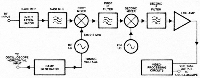
Superheterodyne or swept frequency spectrum analyzer block diagram . The frequency of the local oscillator governs the frequency of the signal that will pass through the intermediate frequency filter. This is swept in frequency (linearly increasing in frequency) so that it covers the required band. The sweep voltage used to control the ... Spectrum Analyzer Block Diagram The crucial component used in the construction of the analyzer is a swept-tuned receiver. The device consists of a mixer, detector, RF type attenuator, local oscillator a LED display section. Spectrum Analyzer with Block Diagram. A Spectrum Analyzer is a frequency selective voltage indicator. Feb 12, 2016 — At first glance, a spectrum analyzer closely resembles an oscilloscope, and in fact many contemporary advanced oscilloscopes incorporate ... seems confusing now - as we discuss the block diagram, the concept will become clearer. We will first go into more detail as to how the swept spectrum analyzer works. Then we will compare that architecture to the architecture of a modern FFT analyzer.
The Keysight MXA signal analyzer features state-of-the-art signal and spectrum analysis, and offers the highest mid-range analyzer performance in the industry today. ... MXA signal analyzer block diagram (RF and analog BB) 1. If 25 MHz bandwidth is sufficient for both RF and baseband, order Option B25 (not S40) with Option BBA. Refer to the ... Block Diagram Description Spectrum analyzer users need to understand major analyzer functional blocks. While most of the choices described here are made automatically, manual selections are possible and can be helpful. The DC block prevents DC voltage from entering the instrument, and allows measuring lines with DC power. Jun 30, 2019 · The internal architecture (Functional Block Diagram of 8085 Microprocessor) is shown in figure. The following are the functional blocks in the 8085 Microprocessor. 1. The figure below shows the block diagram representation of a spectrum analyzer with digital display: As we can see the spectrum analyzer is composed of components like RF attenuator, mixer, IF filter, detector, sweep generator, local oscillator and display unit. So, let us now understand the operation performed by each block individually.
Block diagram of a Spectrum Analyzer-Draw a block diagram of a spectrum analyzer, and explain brie⁄y each of the following blocks (Attenuator,ampli-er,LPF, IF -lter, envelope detector, video -lter, display, LO, Ramp generator). 1.3.4 Problem-4 Shape factor of a Gaussian -lter-The voltage of a gaussian shape -lter is given by V (f ...

In this diagram T refers to the analyzer's time record for FFT processing. The analyzer collects a block of contiguous samples from the ADC that is digitizing the IF signal and then performs an FFT to obtain a power or vector spectrum. This sample block may vary in size or it may be fixed.
Spectrum Analyzer Block Diagram The crucial component used in the construction of the analyzer is a swept-tuned receiver. The device consists of a mixer, detector, RF type attenuator, local oscillator a LED display section.

Figure 2: A diagram of an RF attenuator, the first block of a spectrum analyzer. An RF attenuator, shown in Figure 2, ensures the signal enters the mixer at an optimum level. If a signal is too high in amplitude, it may overload the mixer, leading to distortion. This component protects the analyzer from damage.
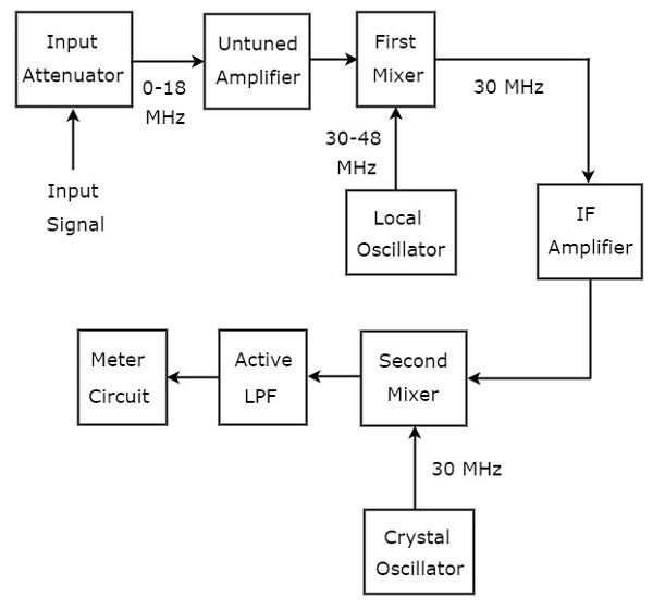
Superheterodyne Wave Analyzer. The wave analyzer, used to analyze the signals of RF range is called superheterodyne wave analyzer. The following figure shows the block diagram of superheterodyne wave analyzer. The working of superheterodyne wave analyzer is mentioned below. The RF signal, which is to be analyzed is applied to the input attenuator.

Block Diagram of a Mass Spectrometer Ion Source Mass Analyzer Detector "High" Vacuum Sample In Computer 400 600 800 1000 1200 1400 1600 1800m/z 0 20 40 60 80 100 Relative Abundance Mass Analyzer Activation or Reaction Tandem Mass Spectrometry or MS/MS

The Dewesoft FFT spectrum analyzer has it all: top performance, real-time FFT analysis, advanced cursor and marker functions, high freely selectable line resolution, flexible averaging, and advanced functions for in-depth frequency analysis.. And, in addition to great performance, the Dewesoft FFT analyzer includes lifetime free software upgrades and the industry’s best 7 …
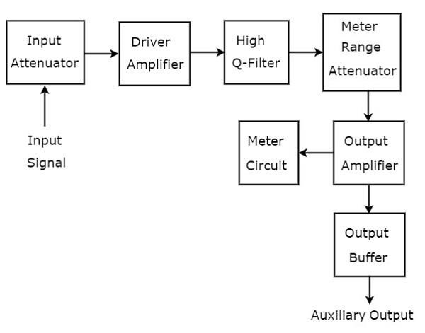
Analyzer Block Diagram Block Diagram. The block diagram of the spectrum analyzer is shown above. It consists of an input attenuator, which attenuates the input radio frequency signal. The attenuated signal is fed to a low pass filter to eliminate the ripple content. The filtered signal is mixed with a voltage tuned oscillator, and fed to an ...
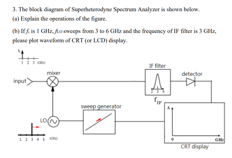
The spectrum analyzer, used for analyzing the signals are of RF range is called superheterodyne spectrum analyzer. Its block diagram is shown in below figure. The working of superheterodyne spectrum analyzer is mentioned below. The RF signal, which is to be analyzed is applied to input attenuator. If the signal amplitude is too large, then it ...

Add a Spectrum Analyzer block to your block diagram.. If your model uses a variable-step solver, also add a Rate Transition block and connect it to the input of the Spectrum Analyzer, setting the Output port sample time to the sample time you wish the Spectrum Analyzer to use.. If your model uses a local solver, then it produces output physical signals with discrete sample times and you do not ...
a spectrum analyzer. 2.2 Spectrum Analyzer Block Diagram and Theory of Operation The main components of Spectrum Analyzer are an RF input attenuator, input am-plifier, mixer, IF amplifier, IF filter, envelope detector, video filter, CRT display, LO, ramp generator(see Fig - 2 ). Lets describe each component individually

The spectrum analyzer, like an oscilloscope, is a basic tool used for observing signals. Where the oscilloscope provides a window into the time domain, the spectrum analyzer provides a window into the frequency domain, as depicted in Figure 1. Figure 2 depicts a simplified block diagram of a swept-tuned superheterodyne spectrum analyzer.
Spectrum. Spectrum analyzer. • Transmission/Refection. Network analyzer characteristics ... Block Diagram of the Super-Heterodyne Method.18 pages
2.6 Microwave Spectrum Analyzer Block Diagram Modern microwave spectrum analyzers are usually a combination of a fundamental frequency analyzer and a harmonic analyzer. The fundamental frequency method of operation is used at the Iower frequencies but at the higher frequencies the multiplication technique, with a preselector, is used.

Figure 3. Block diagram of simplified vector signal analyzer and signal processing flow. Nearly all modern spectrum analyzers combine the features of both the traditional swept spectrum analyzer and a vector signal analyzer. If the span is greater than the FFT analysis bandwidth, the LO will be stepped

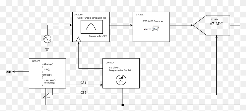
Aug 27, 2016 · Arduino capability for measuring signals and converting them to logic that the micro-controller (MCU) can process is provided by the Analog-to-Digital-Converter (ADC) that is pat of the MCU. Therefore, for an Arduino implementation, this process translates to connecting a measuring device (microphone for sound) to the MCU and sampling the value at the device by …
This video describes the architecture and functionality of the Spectrum Analyzer.
spectrum analyzer will be examined. 7.1 Modulation With the proper equipment, radio signals can be transmitted and received over large distances. Information may therefore be exchanged over large distances by encoding information on radio ... A block diagram of the demodulation process is shown in Figure 5. cos ...

function of frequency. Unlike wave analyzers. spectrum analyzers provide a graphical display on a CRT. A block diagram of an audio spectrum analyzer.20 pages
Graphical block diagram environment improves productivity when working with complex analysis systems Custom tools and workspaces can be created and later reused or exchanged with other SIGVIEW users Various command-line options for automation and remote control from external applications or from simple batch files
Simple Spectrum Analyzer Adaptor For Scopes Circuit Under Meters Circuits 14884 Next Gr. An Inexpensive Spectrum Analyzer For The Radio. Audio Spectrum Analyzer Easyeda. Block Diagram For Spectrum Analyzer Scientific. A Working Sprectrum Analyzer Schematic All About Circuits. Agilent Technologies 8 Hints For Spectrum Analysis.


0 Response to "37 spectrum analyzer block diagram"
Post a Comment