37 walk in freezer defrost timer wiring diagram
Walk In Freezer Defrost Timer Wiring Diagram Effectively read a electrical wiring diagram, one provides to find out how the particular components within the system operate. For example , when a module is usually powered up and it also sends out a signal of 50 percent the voltage and the technician would not know this, he would think he offers ...
I will put defrost timer in series with the thermostat and pumpdown solenoid. Presently, the condenser is on the roof with the walk-in about 20' away inside the store. The defrost timer is inside the condenser. I would have to run some conduit and wiring from the pumpdown solenoid to the timer which is more work than moving the timer to the ...
October 19, 2021 - 404 Not Found · nginx
Walk in freezer defrost timer wiring diagram
Bfreezer Defrost Timer Wiring Diagrams Wiring Diagram . Freezer Defrost Timer Wiring Diagrams Paragon 8145 00 . Wiring Diagram For Defrost Timer Wiring Diagram User . Sanyko Type Plastic Defrost Timer For Refrigerator Tmde706sc . Defrost Timer Refrigerator Cozy Home Design For You Newopa . Defrost Timer As Well Whirlpool Refrigerator Defrost ...
Feel free to contact us via phone or just send us an email · 10914 NW 33rd St. #100, Miami, FL 33172 USA Tech Support: +1(800) 226-9550 Phone: +1(305) 406-2331 E-mail: sales@everwellparts.com
October 19, 2021 - 404 Not Found · nginx
Walk in freezer defrost timer wiring diagram.
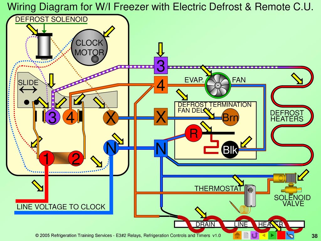
Walk In Freezer Defrost Timer Wiring Diagram Do not set a cooler thermostat below the walk-ins design temperature or product Diagram 9 - Typical Wiring Diagram for Single with Defrost Timer Only. The most common form of defrosting a freezer's unit cooler is done by control for the evaporator is wired to terminal “X” on the defrost timer.
GE- Need wiring diagram/defrost timer issue
Dimension: 960 x 1384. DOWNLOAD. Wiring Diagram Sheets Detail: Name: bohn walk in freezer wiring diagram - Walk In Freezer Defrost Timer Wiring Diagram Unique Heatcraft Freezer Wiring Diagram Jerrysmasterkeyforyouand. File Type: JPG. Source: nezavisim.net. Size: 117.69 KB. Dimension: 1024 x 1460. DOWNLOAD.
Size: 475.25 KB. Dimension: 2533 x 1780. DOWNLOAD. Wiring Diagram Sheets Detail: Name: refrigerator defrost timer wiring diagram - Norlake Walk In Freezer Wiring Diagram Unique fortable Reach In Freezer Wiring Diagram Inspiration. File Type: JPG. Source: kmestc.com. Size: 146.81 KB.
Description: Freezer Defrost Timer Wiring 220V Commercial Freezer Defrost Timer with Walk In Freezer Defrost Timer Wiring Diagram, image size 598 X 452 px, and to view image details please click the image.. Here is a picture gallery about walk in freezer defrost timer wiring diagram complete with the description of the image, please find the image you need.
Shop Our Selection Of Piping Tools, Fire Sprinkler Accessories, Pipe Fittings and More. Order Online Today! Specializing In Providing Quality Products At Great Prices To All Industries. Worldwide Shipping. Over 8,500 Products. Buy In Bulk & Save. Quality Since 1981.
Walk In Freezer Defrost Timer Wiring Diagram from diagramweb.net To properly read a cabling diagram, one provides to know how the particular components inside the system operate. For instance , if a module is powered up and it sends out a signal of half the voltage and the technician does not know this, he'd think he has an issue, as he would ...
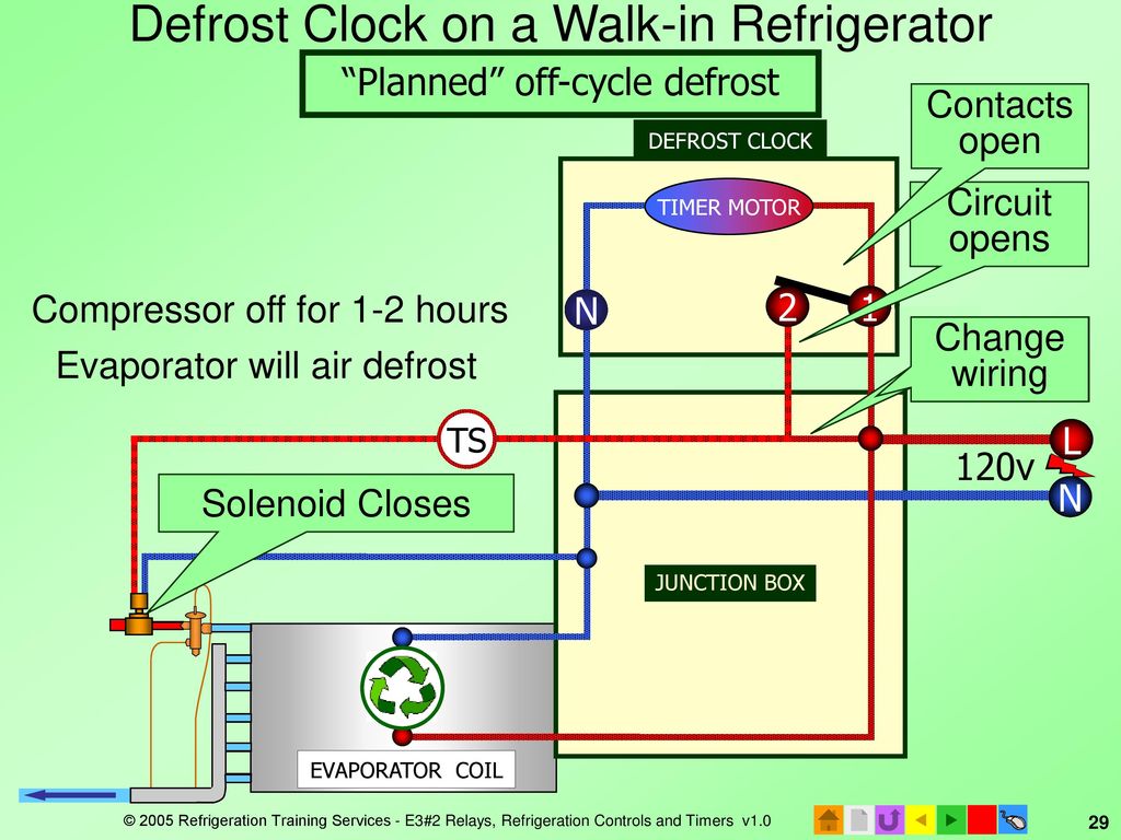
In a common wiring diagram for a time-initiated, temperature-terminated electric defrost system the time motor (TM) is energized continuously. Normally closed contacts 2-4 of the defrost timer are wired in series with the compressor and the evaporator fan motor (EFM).
Walk-In Cooler Defrost. Share this Tech Tip: Facebook 0 Tweet 0. ... The easiest way to correct this problem is to relocate the defrost timer into the evaporator and break power to the liquid line solenoid valve during defrost. The diagram below shows how it was initially connected and then how we rectified the situation.
Aug 8, 2019 - Wiring Diagram For Chinese 110 Atv, best images Wiring Diagram For Chinese 110 Atv Added on Wiring Diagram – floraoflangkawi.org
WALK IN FREEZER PARAGON DEFROST CONTROL.
2、Walk-in Cooler & Freezer Application . The walk-in coolers are walk-in freezers are used in a variety of temperature ranges. z. High temperature walk-in cooler: used for holding fruits, vegetables, eggs, medicine and wood. z. Medium temperature walk-in freezer: used for holding meats, seafood and stuff that needs the same temperature ...
April 9, 2017 - Heat measured in hvac system basic and tutorials. In this video you can learn about the defrost timer wiring diagram of a frost free refrig...
January 4, 2021 - There are many different ways to control defrost but, in light commercial refrigeration applications a defrost control timer is most often used.
April 6, 2009 - What happens if a system doesn't have a defrost/termination/fan delay control?
From the thousands of photos on the web about walk in freezer defrost timer wiring diagram, we all choices the best choices with ideal quality simply for you, and this photos is usually among pictures selections in your ideal photographs gallery with regards to Walk In Freezer Defrost Timer Wiring Diagram.I'm hoping you will like it. This kind of picture (Freezer Wiring Diagram Walk-In ...
• Retail store display freezers and reach-in coolers • Supermarket display cases for produce and meats • Retail store walk-in coolers and freezers • Boiler operating control (used as a thermostat) • Condenser fan cycling or staging ... Universal Defrost Timer - Wiring. Convert to 9145 Convert to 9045 Convert 8141 to 9145 8141 N 1 4 32 X
We understand this kind of Freezer Defrost Timer Wiring Diagram graphic could be the most trending subject in the same way as to part it for Google help or Facebook. We try to introduce it in this posting in the past this may be one of excellent mentions for any Freezer Defrost Timer Wiring Diagram options.
Common elements in the wiring diagram are ground, power supply, wire and connection, output devices, switches, resistors, logic gates, lights, etc. A list of electrical symbols and descriptions can be found on the “Electrical Symbols” page. Line junction. One line represents the wire. Used to connect components to the wire.
Walk-In Freezer Defrost Timer Wiring Diagram from www.applianceblog.com DIY enthusiasts use cabling diagrams nevertheless they are also common in home building plus auto repair.
CONTROL NEWS YOU CAN USE ControlTrends was created for the ControlPro that needs useful information, free training videos, and ideas on how to be more profitable and successful. STAY IN THE LOOP WITH OUR PODCAST CONTROL TRENDS PROUDLY PRESENTS THE ANNUAL . . . BE IN THE KNOW.
Walk In Freezer Defrost Timer Wiring Diagram. Variety of walk in freezer defrost timer wiring diagram. A wiring diagram is a streamlined standard pictorial representation of an electrical circuit. It shows the components of the circuit as simplified forms, and also the power as well as signal connections in between the gadgets.
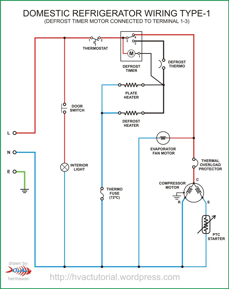
Defrost Timer Wiring Diagram, furthermore 2 2 ecotec timing marks diagram together with wiring diagram for intermatic t pool pump along with refrigerator ptc relay furthermore walk in freezer defrost timer wiring diagram together with dodge ram radio wiring diagram furthermore domestic refrigerator wiring as well as plant cell.
The defrost timer is operated by a single-phase synchronous motor like those used to operate electric wall clocks, Figure 28-1. The contacts are operated by a cam that is gear driven by the clock motor. A schematic drawing of the timer is shown in Figure 28-2. Notice that terminal 1 is connected to the common of a single-pole double-throw ...
DEFROST. TIMER. Step 3: Test the defrost timer with a VOM set to the RX1 scale. Clip one probe of the VOM to each defrost timer -- not motor -- wire, and turn the timer control. Defrost Timer Controls. – Series Defrost Timers Retail store display freezers and reach-in coolers Typical line voltage wiring diagram. 3.
Walk-In Freezer Defrost Timer Wiring Diagram Collection. Fixing electrical wiring, more than any other home project is focused on protection. Install an electrical outlet correctly and it's because safe as that can be; set it up improperly and it can potentially deadly.
June 5, 2006 - When troubleshooting walk-in freezers, technicians often find a frozen evaporator coil. Although there are several possible causes, one common cause involves the defrost system. In order to effectively troubleshoot this problem, a technician must understand the design and operation of the defrost ...
Retail store walk in coolers and freezers boiler operating control used as a thermostat universal defrost timer wiring. Wiring diagram a schematic drawing of the wiring of an electrical system. This type of wiring diagram has branch runs all shown as parallel circuits going from the left line l1 to the neutral line n.
Ge Defrost Timer Wiring Diagram - wiring diagram is a simplified welcome pictorial representation of an electrical circuit. It shows the components of the circuit as simplified shapes, and the knack and signal connections amongst the devices.
Walk In Freezer Defrost Timer Wiring Diagram from diagramweb.net Print the electrical wiring diagram off plus use highlighters to be able to trace the circuit. When you make use of your finger or even the actual circuit together with your eyes, it may be easy to mistrace the circuit. 1 trick that I actually 2 to print a similar wiring picture ...
Quality on-line retailer of genuine appliance parts, electrical accessories for your home appliances.
October 18, 2021 - 404 Not Found · nginx
Source: Walk In Freezer Defrost Timer Wiring Diagram from tse2.mm.bing.net. Source: Walk In Freezer Defrost Timer Wiring Diagram from www.refrigerationbasics.com Source: Walk In Freezer Defrost Timer Wiring Diagram from static-cdn.imageservice.cloud Source: Walk In Freezer Defrost Timer Wiring Diagram from epicwiringx1.hdr-org.de
Arctic Industries has been providing outstanding quality and value in the walk-in cooler and walk-in freezer industry since 1981.
Aug 9, 2021 - Walk In Freezer Defrost Timer Wiring Diagram . Unique Walk In Freezer Defrost Timer Wiring Diagram . nor Lake Walk In Freezer Wiring Diagram.
Feb 19, 2019 - freezer defrost timer wiring diagrams, kuwaitigenius.me
norlake walk in freezer wiring diagram - norlake walk in cooler wiring diagram Collection walk in freezer defrost timer wiring diagram 7 DOWNLOAD Wiring Diagram Sheets Detail Name norlake walk. File Type: JPG. Source: faceitsalon.com. Assortment of norlake walk in freezer wiring diagram. Click on the image to enlarge, and then save it to your ...
Many of the refrigeration appliances used in the home are “frost-free.” The frost-free appliance could more accurately be termed “automatic ...
Wiring Diagram – Freezer ½ to 2 HP Single Phase. .. Set the correct time of day on the defrost timer. Do not set a cooler thermostat below the walk-ins design temperature or product Diagram 9 - Typical Wiring Diagram for Single with Defrost Timer Only.Jul 02, · I can increase the defrost time (Grasslin timer), but don't believe it will be ...
Wiring for a single evap freezer system or reach in freezer. Any questions or comments Feel free to ask in the comment section . Thanks for watching 👍. ...


0 Response to "37 walk in freezer defrost timer wiring diagram"
Post a Comment