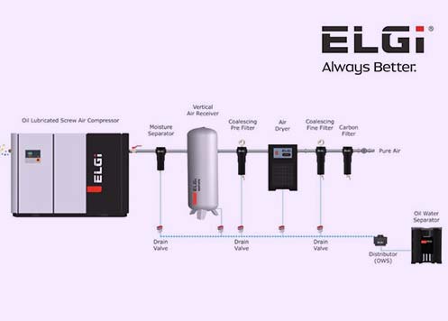
38 air compressor dryer installation diagram
Remove wet air by installing a refrigerated or desiccant dryer from Compressor World. Compressed air dryers are used to eliminate water moisture from your air compressor lines. Whether you're looking for an industrial or medical grade compressed air dryer, we offer a wide selection of air dyer systems and parts. Shop today for the best prices and free shipping from the experts at Compressor World!
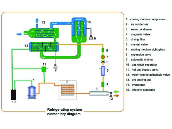
Figure 6. Refrigerated Air Dryer Thermodynamic Diagram. Automatic Drain. Just like in a compressor, the auto drain functioning is critical for the proper operation of a refrigerated air dryer. It drops out the mass of water it condenses. If the drain doesn't open, liquid water will be evaporated in the re-heater, and passed downstream.
The incoming air must be free from smoke or flammable vapours which could lead to explosion or fire risks. 2.3 INSTALLATION 1. Connect the dryer to the compressed air lines indicated in the diagrams below. If not already Before attempting any installation operation, make sure that No part of system is under pressure.
Air compressor dryer installation diagram
In vehicles utilizing a DLU, a naturally aspirated air compressor or non-computerized engines, the HD-2000 air dryer is required, as the compressors will continue to pump air through the air dryers purge port. The air dryer's check valve closes during the non-pumping cycle of the compressor. With the check valve
Circuit Wiring for a 240 Volt Air Compressor. Circuit Size for an Air Compressor The circuit size will depend on the size of the air compressor and the horsepower rating of the motor. The air compressor users manual will specify the required power source. A dedicated circuit will be required for most larger air compressors.
Big sandy recc paintsville ky 606 789 4095. This is simple to read and easy to use. Eimed60jmb dryer pdf manual download. I have a new sanborn 80 gal 240volt single phase 52 hp air compressor. Make sure you use this to check voltages before connecting. View and download electrolux eimed60jmb wiring diagram online.
Air compressor dryer installation diagram.
Reduce the moisture within your air compressor piping diagrams by changing the supply inlet. This helps because water is heavier than air and drops to the bottom of the tank. Taking air from the top of a compressor means that the amount of moisture taken with it too is reduced. We also recommend that you have an aftercooler fitted with your ...
H. Connect electric power, according to the wiring diagram and nameplate power requirements, to the electrical terminals. The refrigerated dryer is designed to run continuously; therefore, it must be wired separately from the air compressor cycling switch. The dryer must not cycle with the air compressor. All units are prewired internally.
26.0 flow diagram 27.0 pressure switch adjustment 28.0 dryer calibration 29.0 voltage conversion - wiring diagram (on the back cover) important: a copy of the wiring diagrams can be found inside the electric board of the compressor. rotary screw compressor units hp 3 - 5 - 7.5 kw 2.2 - 3.7 - 5.5 machine and manufacturer identification data
desiccant air dryers can provide the correct air quality, without the need for drying the complete compressed air installation, which can be both costly and totally unnecessary. Sources of contamination found in a compressed air system Contaminants in a compressed air system can generally be attributed to the following:
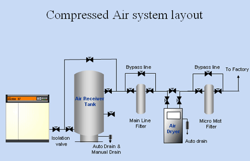
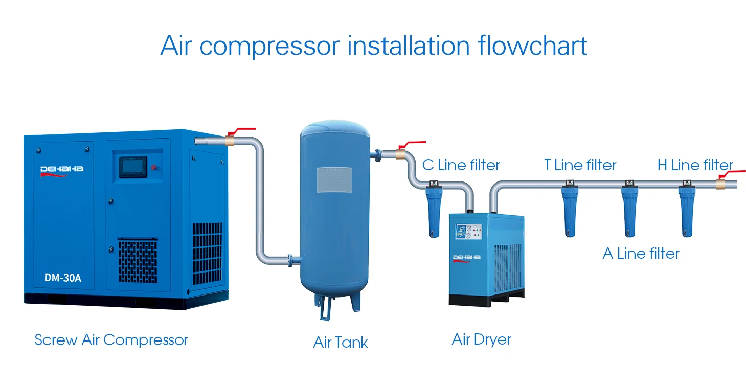
Every company's needs are unique, but when installing a compressor system, we generally recommend that systems include a wet receiver between the compressor and air dryer and a dry receiver after the dryer. The compressor should have a moisture separator. The dryer should have a pre-filter and an after filter.
2 D) For air cooled dryers, clean the air condenser as soon as it's dirty or clogged. E) For optional water-cooled condensers, use only clean water and install a water filter if needed. Use water counter flow to clean condenser if need. F) Check the trouble-shooting list in case of maintenance troubles. G) Check operating pressures, temperatures and time settings after maintenance.
How to install air compressor lines and air dryer for air compressor. You can buy the Air Dryer here: http://www.usaweld.com/Max-Dry-for-Plasma-Cutters-p/253...
Kaeser Wiring Diagrams Wiring Schematic Diagram 11 Laiser. Kaeser Es280 220hp Air Compressor. Kaeser Sigma Rotary Screw Air Compressor Air Dryer Package Dcm. Sam2 Sam2 User Manual Prodrive. Https Www Kaeser Com Int En Download Ashx Id Tcm 17 5981. Cccb Puma Air Compressor Wiring Diagram Wiring Resources.
Air compressor After Cooler Section: The air passed through a aftercooler section where air temperature will be reduced & moisture will be condensates. Air compressor Receiver tank: It provides momentary reserve capacity, to improve regulation and to ensure a smooth flow through out the system.
26.0 flow diagram 27.0 dryer calibrations 28.0 voltage conversion - wiring diagram (on the back cover) important: a copy of the wiring diagrams can be found inside the electric board of the compressor. screw compressor units hp 10 - 15 kw 7,5 - 11 machine and manufacturer identification data position of the identification plate fig. 1 fig. 1 1
Advanced 3-in-1 compressed air dryer system features modes for pre-refrigeration, evaporation, and air and moisture separation to remove up to 90% of the moisture from your compressed air lines. When you prevent too much moisture in compressed air, you can avoid problems like corrosion of equipment and freezing of outdoor compressor air lines.
- Allow no open flame and flying sparks in the place of installation. - During any necessary welding on or near the compressor package ensure that sparks or high temperatures cannot cause fire or explosion. - Ensure that clean air without damaging impurities is fed to the compressor package.
C. The air dryer has been installed in a system that has been previously used without an air dryer. This type of system will be saturated with moisture and several weeks of operation may be required to dry it out. D. Location of the air dryer is too close to the air compressor. Refer to Locating AD-9 ® Air Dryer On
Home / User Manuals Stationary Compressor Manual PISTON MANUAL - REV022621.1 Piston Pump Manuals 5HP INLINE PUMP MANUAL REV030921 7.5-10HP V4 PUMP MANUAL REV030921 Freight Train Manual FREIGHT TRAIN MANUAL REV081321 Smart Air Compressor Manual Smart Air REV032921 Rotary Screw Air Compressor Manuals Eaton Compressor Rotary Screw Manual LogikaControl PLC - Logik 25-S LogikaControl PLC […]
Add a Dryer/Separator. For added protection against moisture and other fluids, be sure your air compressor setup is linked to an air dryer and oil/water separator. The two devices can be linked with a short airline between the outlet of the dryer and inlet of the separator. ... Air compressor installation is a useful undertaking for the avid ...
† The air dryer mounting method must be rigid enough to avoid vibration which could damage the desiccant or dryer. † The air dryer must not incline in any direction more than 15° from vertical position. † The air dryer must have at least 0.5 in (12.5 mm) free space above the cartridge canister to allow for removal during service.
Air Compressor Installation. That Sears Craftsman 2 hp 33 gallon vertical compressor had done an excellent job for me, but I wanted a better compressor. I wanted a stationary/fixed compressor with more horsepower, and my choices basically boiled down to whether to purchase a 2 stage model or get crazy and buy a rotary screw compressor.
The AD-IS ® air dryer and reservoir system is designed to receive compressed air from the vehicle air compressor, clean and dry the air, deliver air to the vehicle's primary reservoir, secondary reservoir and accessories, and control the compressor/dryer charge cycle. AIR DRYER AND RESERVOIR SYSTEM OPERATION: GENERAL
high-performance dryers remove the moisture from your compressed air with a standard pressure dew point of -20°C/-5°F, -40°C/-40°F and -70°C/-100°F. For complete peace of mind, you can even set your dew point to meet the specific needs of your application. Enjoy easy installation and long maintenance intervals
The air compressor on the Dry Air Pac® is designed to fill the sprinkler system with -40 to -60 degree F dew point air in 30 minutes in accordance with NFPA 13 standards, as well as provide the pressure needed to allow the air dryer to function properly. Prior to entering the desiccant beds, an air-cooled aftercooler cools the compressor's hot ...
4.3 Wiring Diagram 5. Installation 13 5.1 Storage ... compressor house. The dryers have been designed for nominal standard inlet conditions as per ISO 7183 in order to obtain a dew point under pressure of +3oC to +7C. ... The Air Dryer is switched ON/OFF using Dryer ON/OFF switch. The moment Dryer is switched ON, built in Anti-Recycling
4. Plug in and turn on your compressor and you're ready to work without the Air Dryer. Using the Air Dryer without the bypass valve. 1. Before plugging in the compressor or the Air Dryer, open both of the shut-off valves. 2. Close the bypass valve. 3. Plug in and turn on the Compressor and Air Dryer. Shut-off Shut-off Electrical Installation ...
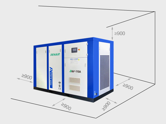
1. A dry, well-ventilated area is the best location for installation of the dryer. It also should be in an area where the ambient temperature will not exceed 40°C or fall below 2°C. 2. A dryer should be kept at a distance from the air compressor in order to prevent






0 Response to "38 air compressor dryer installation diagram"
Post a Comment