39 aerator timer wiring diagram
This aerator control provides a source of oxygen-rich water to your live well automatically. This unit features a solid-state timer with adjustable off times to adjust to varying conditions. Easily adaptable to existing systems. Simply connect wiring according to instructions provided. Front panel is 3 1/4 x 3 1/4 and requires only 3" behind panel. A dictionary file. dict_files/eng_com.dic This class can parse, analyze words and interprets sentences. It takes an English sentence and breaks it into words to determine if it is a phrase or a clause. It can also counts the total number of words in a sentence, checks if a word is a palindrome and can generate a new sentence with almost the same meaning using synonyms …
institutional research committee, idm: internal protocol for . financial review of idm research proposals and ; study protocols requiring ethics approval

Aerator timer wiring diagram
Control Box Wiring Diagram: control-box-wiring-diagram-2-3hp.pdf Scott Aerator's fountains, aerators, de-icers and Aquasweep products are proudly made and built right here in Holland, Michigan! 1-800-water-45 1-800-928-3745 Tracker aerator problem. I have a 2005 tracker and the aerator quit working. The pump works when hooked up to the battery. So the problem is in the switch or the timer. It looks like both the manual and the auto go through the timer. Any idea where I can find a wiring diagram? Palestine, Illinois, USA. data:image/png;base64,iVBORw0KGgoAAAANSUhEUgAAAKAAAAB4CAYAAAB1ovlvAAACs0lEQVR4Xu3XMWoqUQCG0RtN7wJck7VgEW1cR3aUTbgb7UUFmYfpUiTFK/xAzlQWAz/z3cMMvk3TNA2XAlGBNwCj8ma ...
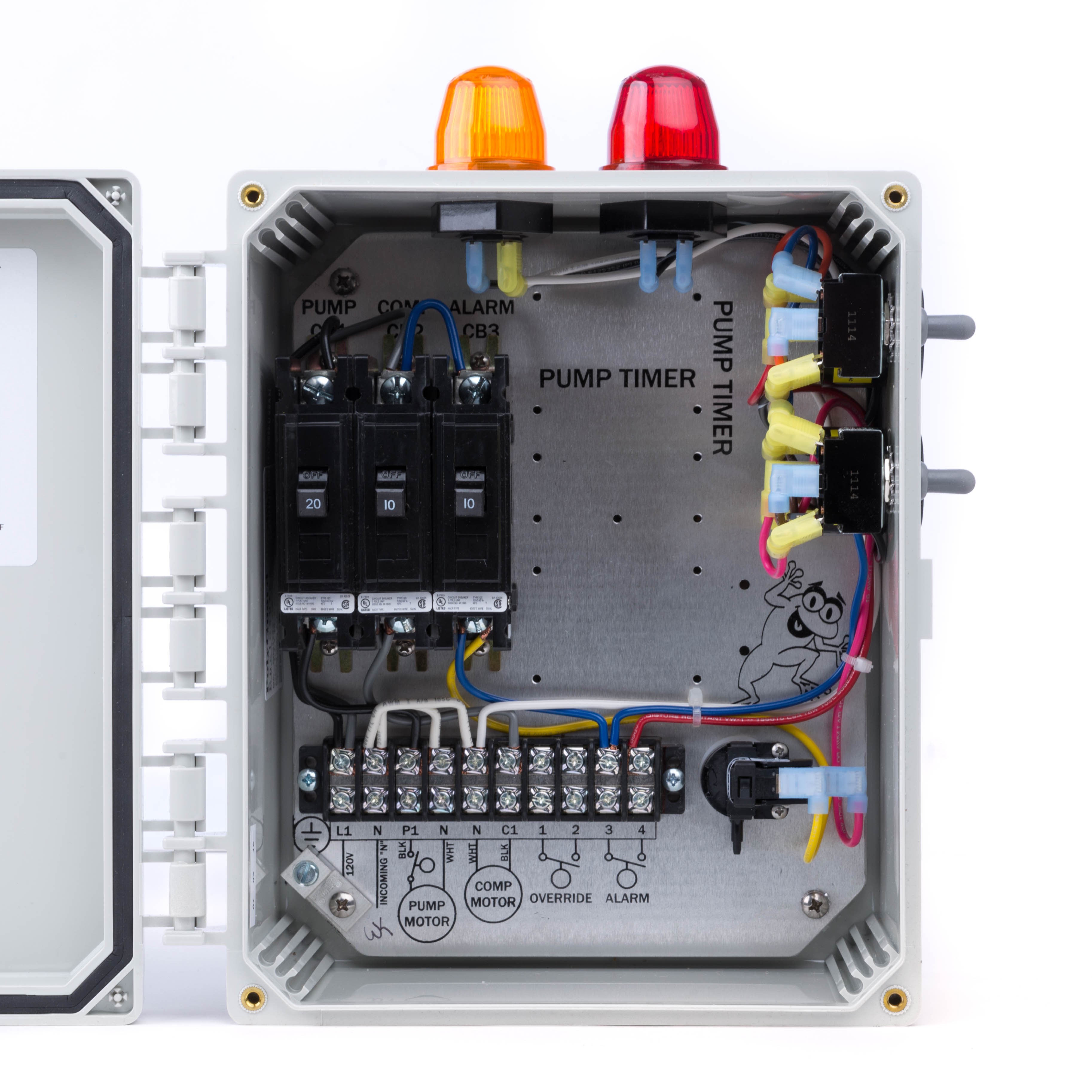
Aerator timer wiring diagram. Its components and wiring are protected within a lockable, corrosion resistant, ultraviolet-stabilized thermoplastic enclosure with removable flanges. Control Panels 180 -194 Audible Alerts Optional Warning Light Optional Timer* Terminal Strip Aerator Warning Light Circuit Breaker Control Switch Model # Part # Standard Features 180-194 Control ... Join our eBook service for unlimited Manual Books & Wiring Diagram. Please create a FREE ACCOUNT to continue reading or download! Variable Livewell Timer Variable Livewell Timer On cycle pumps for Variable Livewell Timer On cycle pumps for 30-seconds, Off cycle is variable from 0 to 5-1/2-minutes. Allows for continuous run for filling live well. Keeps bait or fish alive without draining battery down. 3 wire installation easily replaces your on off switch. 3/8 in. mounting hole for dashes up to 1 in. thick. RED ALERT AERATION TIMERS Features Red Alert™ aeration timers are designed for both indoor and outdoor use. Red Alert timers are a superior choice for time control on most aerator types including shaft-style, submersible, compressor or blower aerators, and for any application that requires mini-breaker (7 amp) capability.
Aerator provides complete treatment Our exclusive aerator infuses the fresh air that safe, living micro-organisms require to fully digest and treat wastewater inside the Aeration Chamber. Powered by our 1725 RPM, 115 volt, fractional horsepower motor, our quiet, reliable aerator is inexpensive to 1. Repair or replace aerator 2 to 10 years 2. Clean filters on aerator 6 mos. to 2 years 3. Break up scum in clarifier 6 mos. to 2 years 4. Pump sludge from aeration tank 2 to 5 years* 5. Pump sludge from pretreatment tank 2 to 5 years* 6. Check aeration diffusers annually 7. Check surge control weir 6 mos. 8. Repair or replace effluent pump 2 ... Grasslin 24 Hour timer with 15 minute intervals. 16A Max, 120VAC These timers are commonly used in Aerobic System Control Panels. Out of Stock $53.00 MSRP: $79.00 Simple wiring diagram included. Sealed case. 3 industrial grade terminals come with crimp-on wire connectors to resist corrosion and loosening. Water resistant, but for protected in-dash installation. Threaded brass shaft fits panels up to 5/8" 4" x 1" x 1.75", including knob. Drill one 3/8" hole. Requires 4" clearance behind panel.
Is there a timer as well? 3 or 6 post switch? ... I am looking for a wiring diagram for 2003 tracker pontoon party barge. I have a dead short to mainline fuse to the panel. ... I have a Tracker Targa 18 Combo and the forward aerator keeps operating in auto mode even though the switch is in the off position. aerator or water circulator is plugged into a GFI protected circuit. • 3 phase aerators (2.3, 3.3, 5.3) require a startup test after wiring to ensure proper rotation of the propeller. If the propeller is rotating in the op-posite direction, the unit will not perform properly and internal damage to the unit may occur. (See 3 phase startup ... Wiring My Boat For Blue Water Led Lights Bass Fishing Forums The Bs. Wiring diagrams and wire colors for 1998 stratos 283 nightmare 97 201 pe fuel gauge power i have a 1989 bass boat the 10 basic rules boats off 66 trailer diagram tacklereviewer javelin mercury outboard chrysler stratos1 original parts 115 johnson civic stereo new 2001 ss extreme series livewell timer installation my blue ... 10 Aug 2010 — I made a rough wiring schematic of the way I would like to wire up my aerators and attached it. My boat has 2 fresh water aerators and 2 ...Manual/Auto Aerator Switch - Iboats Forums28 Dec 2012TH Automatic Aerator Control - Wiring Diagram??? - Iboats ...14 Oct 2013Stratos Aerator wiring issue. - Iboats Forums8 Feb 2012Aerator Livewel wiring - Iboats Forums25 Feb 2010More results from forums.iboats.com
electrical schematic and wiring diagram. If the delivery occurs before there is a place to install these components, they should be stored out of the elements and protected from damage until they can be installed. INSTALLATION REQUIREMENTS: The installation of an OxyPro is relatively simple, but should be performed by qualified personnel only.

The Extreme series is the upper left diagram. wiring diagram included. boat aerator livewell timer, 30 seconds x 3 minutes, 10 amp model lws-m. $ buy it now. or best offer. free shipping. 10 amp output.
Livewell timer Installation Diagram, Installation Diagram, how to install livewell timer, how to wire a livewell timer, livewell timer wiring diagram. I need a generic wiring diagram for my aerator and recirc/pumpout switches. Both the bow and the console have illuminated on/off/on switches. Astronomical time clock wiring diagrams ranger ...
As the diagram indicates, it is considered desirable to have ready circulation from the entrance foyer to the activity elements of the kitchen, living room, and sleeping areas and at the same time to maintain degrees of separation among these three elements . Ideally, each space in an apartment should have access or exposure to the outdoors . However, application of this …

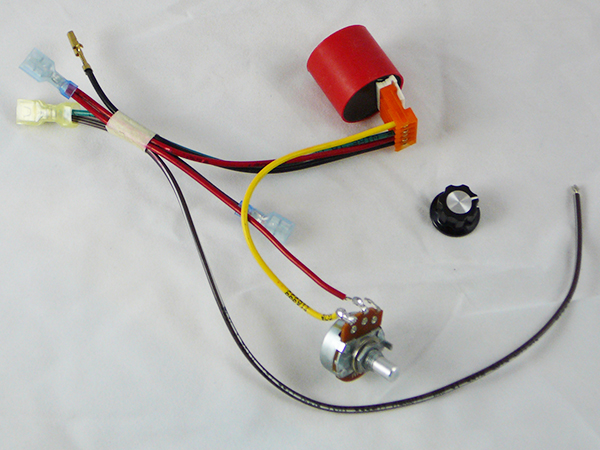
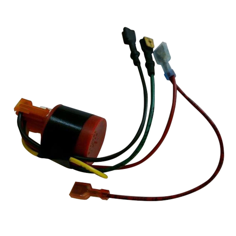
Thousands of these aerator timer modules have been used by most of the major boat builders for the last eight years. By the nature of their design, the life of any aerator timer is five to ten years. Meaning the need for replacement will be now and into the future. The module simply plugs into the wiring harness on the timer switch.

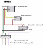
HOOK UP DIAGRAM Installation Select a location for mounting the Control Panel, cut a hole 1-7/8" x 1-5/8" (see sheet 2), secure panel with #8 sheet metal screws. After mounting panel, string wire to battery and pump areas. The RED wire connects to the Battery (+) positive, the BLACK wire connects to the Pump (-)

Congratulations on your purchase of the Flow-Rite ProTimer™. The ProTimer is designed to ... Attach wires as shown in the wiring diagram on the next page.2 pages

Aerator connec-tion single phase aerators 2400VFX 110-120 5.6 12 C-25 plug in Plug into C-25 3400VFX 110-120 7.3 18 C-25 plug in Plug into C-25 3400HVFX 208-240 3.7 9 Hardwire C-85 plug into or hard-wire C85 4400VFX 110-120 11.3 40 C-25 plug in Plug into C-25 4400HVFX 208-240 5.7 20 Hardwire C-85 plug into or hard-wire C85 8400VFX 208-240 11 40 ...
**Full Parts List Below:***Amazon Electric Section: https://www.amazon.com/shop/TBNation?listId=321RPSYSZZZN3&ref=inf_list_own_tbnation_cp***Switch Panels, A...
Aerator Timer and Alarm For Regenerative Blowers and Vane Pumps. Grasslin 24 HR Timer, 15 Minute Intervals. Item #: 80000-413-SB-JS. Our Price: $ 275.00 MSRP: $299.00 . View Product . Aerobic control panels are designed to control and monitor all of the functions of an aerobic septic system. These functions include supplying power to the air ...

18.08.2021 · More than a year-and-a-half into the COVID-19 pandemic, burnout seems to be on everyone’s lips. Many of us didn’t realise what had hit us when we scrambled to adjust to the sudden upheaval of the workplace, switching to remote work with little or no preparation, or deemed an essential worker and asked to continue business-as-usual in highly unusual …

Big Foot Livewell Aerator Timer. I ask because I could wire up one timer to be used on all 4 aerators. I used 2 aerator motors in my diagram. The fuses for the aerators are shown in the diagram where they are currently installed inline in my 92 Skeeter. I don't think I need the diodes in there, but drew them on the schematic anyway.

A septic aerator is a fairly simple and easy piece to install in your septic system. The aerator is great to use for an older septic system because it helps to add and provide a great amount of oxygen to the septic system. Oxygen is a principal ingredient that helps to break down the waste that travels to and from your septic tank.

• The Floodproof model aerator is totally sealed to protect it from water damage by flooding. It is, however, not designed to operate under water. This aerator is oil-filled and sealed. Do not disassemble it or remove plugs or bolts. • The "Control Panel Instructions" contain a wiring diagram and detailed wiring instructions. These

25 Oct 2019 — Aerator Timer, Not Adjustable. ... Simple wiring diagram included • IP65 Item No. Function 11111 Runs for 30 seconds, pauses every 3 minutes ...
Oct 14, 2013. #3. Re: TH Automatic Aerator Control - Wiring Diagram??? Thanks for the diagram, but the TH controller has only three contacts on the timer, plus the three contacts on the rocker switch. One of the contacts on the timer is ground, leaving only two positive contacts. Problem is in finding out where these two positive contacts connect.
30 Dec 2016 — Does anyone have a wiring diagram or pictures of what their connections look like leading to the timer and switch.Livewell / aerator switch / timer replacement not working26 Mar 2016Aerator dual switch with timer wiring diagram needed.30 Nov 2015help on aerator timer wiring needed - BBC Boards11 Apr 2007Javelin 409: Livewell Aerator / Recirc Switch Wiring12 May 2018More results from www.bbcboards.net

The standard Power Control Center includes a fiberglass NEMA 4X enclosure with twenty-four hour timer control in the auto setting or manual control of the aerator unit, the required motor short circuit, ground fault and overcurrent protection, surge protection, and personnel GFCI protection (except 460V 60Hz. applications).
This aerator control provides a source of oxygen-rich water to your live well automatically. This unit features a solid-state timer with adjustable off times to adjust to varying conditions. Easily adaptable to existing systems. Simply connect wiring according to instructions provided. Front panel is 3 1/4 x 3 1/4 and requires only 3" behind panel.
LIVEWELL TIMER INSTALLATION INSTRUCTIONS. INSTALLATION TOOLS. PUMPS. LEAVE THE PLASTIC CONNECTOR COVER IN PLACE ( black square in middle of timer ) To connect your adjustable livewell timer into your current boat you will need to buy some 16 gauge wire, I recommend buying 3 different colors. One for power (red), one for ground (black), and one for the pump (brown).
Diagram of wires to aerator switches on front of my 1990 Stratos bass boat. Check the drivers manual, it will show the correct fuse and what it protects .

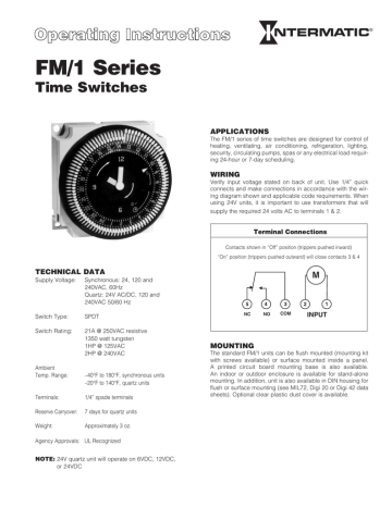
Timer, 230 Volt Commercial STARTING AT: $195.00. This industrial-rated outdoor timer is perfect for our 230-volt fountains and aerators. Manufactured by Intermatic, this heavy-duty timer is designed to save energy while extending the life of your Scott Aerator product.
data:image/png;base64,iVBORw0KGgoAAAANSUhEUgAAAKAAAAB4CAYAAAB1ovlvAAACs0lEQVR4Xu3XMWoqUQCG0RtN7wJck7VgEW1cR3aUTbgb7UUFmYfpUiTFK/xAzlQWAz/z3cMMvk3TNA2XAlGBNwCj8ma ...
Tracker aerator problem. I have a 2005 tracker and the aerator quit working. The pump works when hooked up to the battery. So the problem is in the switch or the timer. It looks like both the manual and the auto go through the timer. Any idea where I can find a wiring diagram? Palestine, Illinois, USA.

Control Box Wiring Diagram: control-box-wiring-diagram-2-3hp.pdf Scott Aerator's fountains, aerators, de-icers and Aquasweep products are proudly made and built right here in Holland, Michigan! 1-800-water-45 1-800-928-3745


0 Response to "39 aerator timer wiring diagram"
Post a Comment