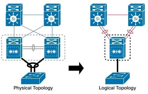
40 physical vs logical network diagram
A physical network diagram illustrates the interconnection of the devices in the network with wires and cables. In contrast, the logical network diagram ...4 answers · 7 votes: A logical network diagram usually shows network devices like routers, firewalls, and voice gateways. ... Data Modeling: Conceptual vs Logical vs Physical Data Model Data modeling is a technique to document a software system using entity relationship diagrams (ER Diagram) which is a representation of the data structures in a table for a company's database.
Logical vs Physical Data Flow Diagrams. Data flow diagrams (DFDs) are categorized as either logical or physical. A logical DFD focuses on the business and how the business operates. It describes the business events that take place and the data required and produced by each event. On the other hand, a physical DFD shows how the system will be ...
Physical vs logical network diagram
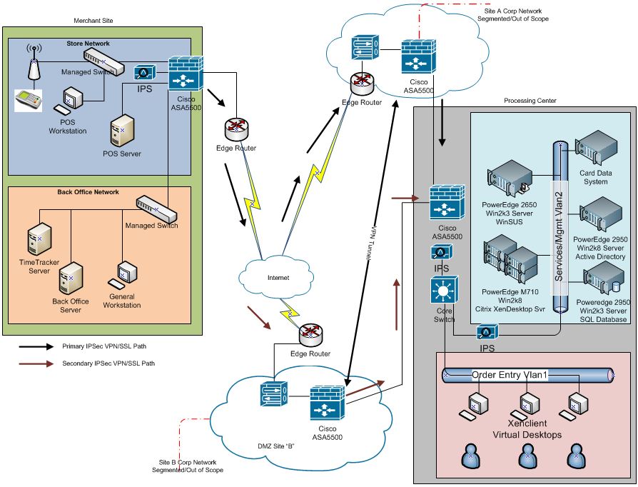
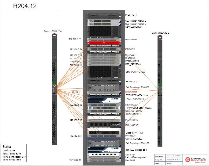
About Press Copyright Contact us Creators Advertise Developers Terms Privacy Policy & Safety How YouTube works Test new features Press Copyright Contact us Creators ... Difference between Physical and Logical Topology : Physical Topology. Logical Topology. Depicts physical layout of network. Depicts logistics of network concerned with transmission of data. The layout can be modified based on needs. There is no interference and manipulation involved here. It can be arranged in star, ring, mesh and bus topologies. A physical network diagram illustrates the interconnection of the devices in the network with wires and cables while a logical diagram Illustrates the way information flows through a network. To be precise, the physical network diagram reveals the network topology with all the physical aspects, such as ports, cables, racks, servers, specific ...
Physical vs logical network diagram. Network diagrams include two different types: logical network diagram and physical network diagram. A logical network diagram explains the logical components of the devices of a network, it includes cables and hardware. Just like the floor plan, it shows the physical layout of a network. A logical network topology diagram shows the logical method of communication used by the devices inside the network for network communication. Physical topology specifies the layout how devices are physically connected in the network. Instead, logical topology specifies the manner in which data travels between devices in the network. Network diagrams are divided into Physical Network Diagrams and Logical Network Diagrams. Network diagram is an indispensable tool for network administrators and engineers at development of new networks and management of existing networks. A logical DFD focuses on the business and business activities, while a physical DFD looks at how a system is implemented. So while any data flow diagram maps out the flow of information for a process or system, the logical diagram provides the "what" and the physical provides the "how.". They are two different perspectives on the same ...
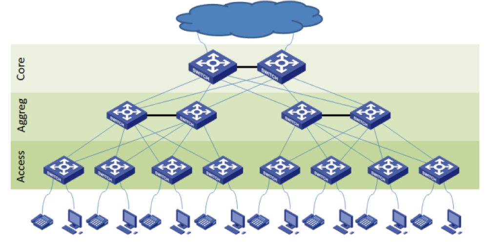
Answer (1 of 4): A logical network diagram usually shows network devices like routers, firewalls, and voice gateways. It shows subnets, VLAN IDs, subnet masks and IP addresses. It also shows routing protocols, traffic flows, routing domains, and network segments. This information corresponds to t... In network topologies, a logical topology often describes the paths that data can take across a network irrespective of how the wires are plugged into each other. A "physical" view of a system describes the "stuff" that makes up the system, or describes how the system is connected together in the physical world. This includes the cables, switches, workstations, routers, and servers. The physical design involves a diagram of the actual way the network will be seen. Below is an illustrated example of the physical design of a network:In conclusion, the difference between logical design and physical design of a network is in the way they are presented. The physical vs. logical network diagram distinction can be boiled down to a difference in scope. A physical network diagram depicts the network topology with the physical aspects like ports, cables, racks, and more. A logical network diagram, on the other hand, shows the “invisible” elements and connections flowing through the physical objects on the network. Therefore, physical vs ...
A logical network diagram usually shows network devices like routers, firewalls, and voice gateways. A physical network diagram shows how the network devices are physically connected together, and therefor all ports on all devices on the network are represented here. This will include cables. Click to see full answer. Physical network topology is the placement of the various components of a network and the different connectors usually represent the physical network cables, and the nodes represents usually the physical network devices (like switches). Logical network topology illustrates, at a higher level, how data flows within a network. A logical network diagram is a pictorial representation of how the computers, printers, fax machines, servers, firewalls, etc., are connected with each other in a physical location. These diagrams tell you how the communication would happen within these devices in a network. The network diagram is like a blueprint that provides the network, IT ... A logical network is a portion of a physical network that connects two or more logical network interfaces or devices. A logical network interface or device is the software entity that is known by an operating system. There is a one-to-one mapping between a physical network interface/device and a logical network interface/device.
Logical and physical view of Trusted Virtual Domains (TVDs). | Download Scientific Diagram
Physical Vs Logical Topology: The potentials of the network access devices and media decides the physical topology of a network. In terms of arithmetic, the physical topology of a network is the real arithmetical arrangement of workstations. Logical topology shows the temperament of the courses the way signals move from node to node.
Logical Network Diagram: A Complete Tutorial | EdrawMax
Logical architecture is a structural design that gives as much detail as possible without constraining the architecture to a particular technology or environment. For example, a diagram that illustrates the relationship between software components. Physical architecture gives enough detail to implement the architecture on a technology.

Physical And Logical Network Diagram - Diagram Media
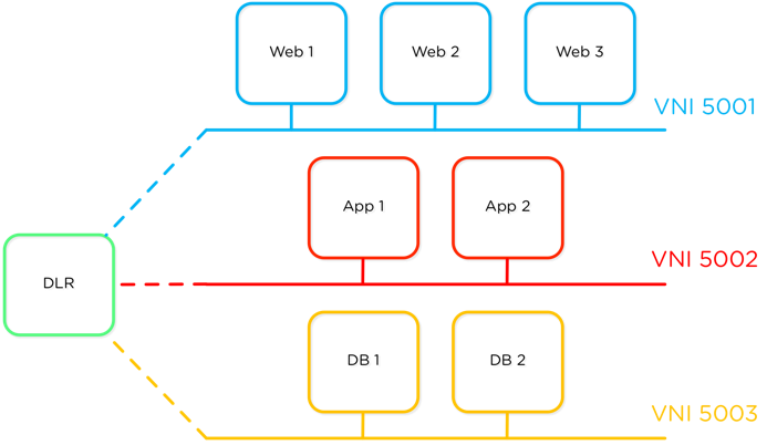
A network diagram can be either physical or logical. Logical network diagrams. A logical network diagram describes the way information flows through a network. Therefore, logical network diagrams typically show subnets (including VLAN IDs, masks, and addresses), network devices like routers and firewalls, and routing protocols.

Plan of Chicago, Chicago, Illinois, Railroad Circuits Diagram (1909) // Daniel Hudson Burnham (American, 1846-1912) Edward Herbert Bennett (American, born England, 1874-1954)
Logical vs. physical network diagrams . There are two types of network diagramming, logical and physical. Therefore, it's essential to understand the differences so you can choose the right kind of mapping for each aspect of your organization. Logical . A logical network diagram illustrates the flow of information through a network and shows ...

white boat on river near mountain under blue sky during daytime
What Is a Physical vs. Logical Network Diagram? Network diagrams are the schematic representations of the underlying physical or logical network topologies. These diagrams consist of nodes and lines, with different icons to make it easy to quickly see different elements on the network. Diagrams can range from hand-drawn maps to automated, highly customizable software diagrams, but regardless ...
Logical vs. Physical connection | Logic, Physics, Networking
The two most common network diagrams you'll come across are physical and logical. Logical network diagrams focus in on how traffic flows across the network, IP addresses, admin domains, how domains are routed, control points, and so on. Within the OSI model of networking, logical diagrams are referred to as 'L2'.

closeup photo of parked vehicle
"Logical topology, or signal topology, is the arrangement of devices on a computer network and how they communicate with one another. How devices are connected to the network through the actual cables that transmit data, or the physical structure of the network, is called the physical topology. Physical topology defines how the systems are physically connected.
How to Draw Clear L3 Logical Network Diagrams - Packet Pushers
Logical vs. physical network diagrams . There are two types of network diagramming, logical and physical. Therefore, it’s essential to understand the differences so you can choose the right kind of mapping for each aspect of your organisation. Logical . A logical network diagram illustrates the flow of information through a network and shows how devices communicate with each other. It ...

unknown
A logical network diagram illustrates the network architecture of a group of interconnected computers and other devices, such as printers, modems, switches, routers, and even mobile devices. These electronic components form the physical network that provides local area network (LAN) and wide area network (WAN) access to users. In addition to this, a physical network in one area can also be ...

Health Sciences Center, Stony Brook, New York, Sectional Diagram (c. 1974) // Bertrand Goldberg American, 1913-1997
Unlike physical topology, the logical topology emphasis on the manner in which data is transmitted between network nodes instead of the physical layout of the path that data follows. An important fact regarding these topologies is that both physical and logical topologies are independent regarding a network, whether it is of any shape and size.
Logical Vs Physical Network Diagram - General Wiring Diagram
But — before I go more in-depth on the physical network view vs. the logical network view — let’s first quickly cover why these types of diagrams are important for businesses to have in the first place. Network diagrams do the following: provide a picture of how your networks operate; help identify network objects, such as routers, firewalls and devices, and show how they are all ...

VMware vSphere 5.5 vMotion on EMC VPLEX Metro - VROOM ...
In short, the logical architecture of microservices doesn't always have to coincide with the physical deployment architecture. In this guide, whenever we mention a microservice, we mean a business or logical microservice that could map to one or more (physical) services. In most cases, this will be a single service, but it might be more.
Logical Network Diagram: A Complete Tutorial | EdrawMax
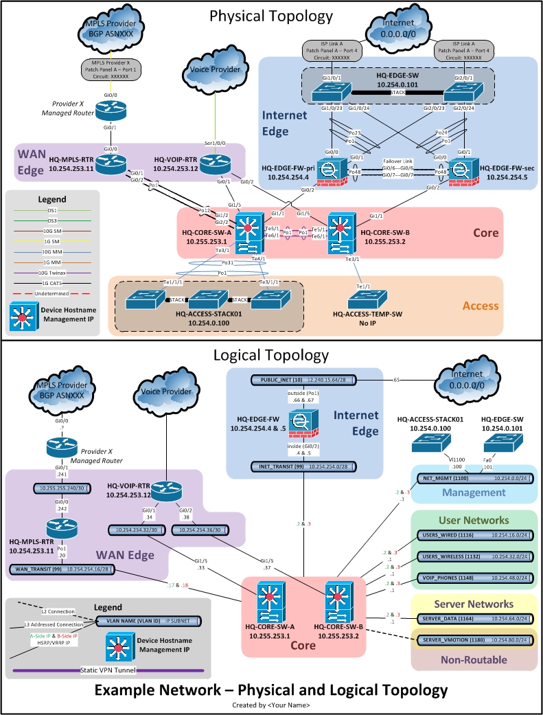
A physical network diagram illustrates the interconnection of the devices in the network with wires and cables while a logical diagram Illustrates the way information flows through a network. To be precise, the physical network diagram reveals the network topology with all the physical aspects, such as ports, cables, racks, servers, specific ...

Marina City Theater, Chicago, Illinois, Roof and Partial Concrete Frame Development Drawing (1961-1962) // Bertrand Goldberg American, 1913-1997
Difference between Physical and Logical Topology : Physical Topology. Logical Topology. Depicts physical layout of network. Depicts logistics of network concerned with transmission of data. The layout can be modified based on needs. There is no interference and manipulation involved here. It can be arranged in star, ring, mesh and bus topologies.

unknown
About Press Copyright Contact us Creators Advertise Developers Terms Privacy Policy & Safety How YouTube works Test new features Press Copyright Contact us Creators ...
Logical Vs Physical Network Diagram - Wiring Site Resource

logical network diagram vs physical - DriverLayer Search ...
Logical vs. Physical Network Diagrams | DCIM, Network ...

grayscale photography of lakeshore during daytime

Logical Vs Physical Network Diagram - Wiring Diagram Database

woman in pink shirt riding on black and red wheel chair

text

Marina City: Finish Diagram (n.d.) // Bertrand Goldberg American, 1913-1997
Cisco Catalyst 4500-E & 4500-X Series Network ...
VMware NSX on Nutanix: Build a Software-Defined Datacenter ...

Block-Neighborhood-Community: Diagram (n.d.) // Bertrand Goldberg American, 1913-1997

green trees on mountain under blue sky during daytime

Lab 114 - Switching Physical to Logical Topology | Coretan ...

😂 Logical network design. Network design checklist: How to ...
5 Best Network Diagram Software + Guide - SolarWinds

unknown

Network Architecture- Basics of Computers for Bank Exams

Drawing: Expressions of Emotion (Hate or Jealousy, Anger, Desire, Physical Pain), from Encyclopédie (1762/77) // A. J. Defehrt (French, active 18th century) after Charles le Brun (French, active 17th century-1765) published by André le Breton (French, 1708-1779), Michel-Antoine David (French, c. 1707-1769), Laurent Durand (French, 1712-1763), and Antoine-Claude Briasson (French, 1700-1775)
shows an example that explains the relationship between physical and... | Download Scientific Diagram

Plate 75 from The Plan of Chicago, 1909: Chicago. Diagram of the City, Showing Complete System of Inner Circuits (1909) // Daniel Hudson Burnham, American, 1846-1912 Edward Herbert Bennett, American, born England, 1874-1954
The logical and physical networks | Download Scientific Diagram

woman jumping near white wall paint

Network Representations and Topologies » CCNA 200-301
San network diagram key - ibiblio.web.fc2.com

Logical Vs Physical Network Diagram - Drivenheisenberg
0 Response to "40 physical vs logical network diagram"
Post a Comment