37 aem wideband wiring diagram
To measure voltage, you are first going to connect wire Analog 1 or Analog 2 to sensor output, then connect the GND wire to sensor GND. Once you have the wires connected, open the latest version of VCM Scanner and add the PID. In VCM Scanner go to External Inputs > MPVI2 > Pro Link, you will then be able to add the PID "MPVI2 AEM gauge type wideband O2 sensor installation 06-99110 Flyin' Miata. Flyin ' ata ... Run a new wire from the white wire on the AEM WBO2 sensor (0 to 5 volt output) to po-sition 2P in the ECU harness. If you need an ECU terminal for this, please contact us as we have them. Here are diagrams of the ECU terminals viewed from the wire side. Flyin ...
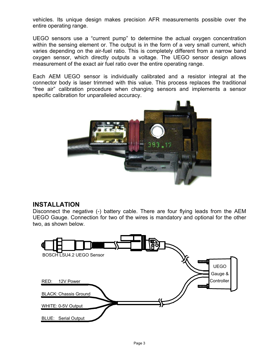
The X-Series UEGO gauge is supplied with a Power/IO wiring harness (A) and a UEGO sensor harness (B); the harnesses are connected to the gauge as shown below. The UEGO sensor harness simply needs to be routed to the UEGO sensor

Aem wideband wiring diagram
Feb 02, 2021 · Aem Wideband Wiring Diagram – aem uego sensor wiring diagram, aem uego wideband wiring diagram, aem uego wiring diagram, Every electrical structure is made up of various different pieces. Each part ought to be placed and connected with other parts in particular manner. 16" WIDEBAND AIR/FUEL RATIO ® MONITOR - ANALOG 2650-1469-00 Rev. B Installation 1. Disconnect the negative (-) battery cable. 2. Gauge can be mounted in a 21⁄ 16". hole with brackets supplied. Gauge can also be mounted in Auto Meter Mounting Cup, or in Auto Meter Gauge Works Pods. 3. Wire gauge as shown. Red Wire (Power): The AEM wideband system consists of the sensor and its loom, ... ECU Lambda Signal Wire. The white signal wire from the AEM gauge is fed into the engine bay, the same as the earth wire. Attaching it to the original narrow-band signal wire will connect it to the correct pin on the ECU. ... the AEM instruction manual gives a diagram of the ...
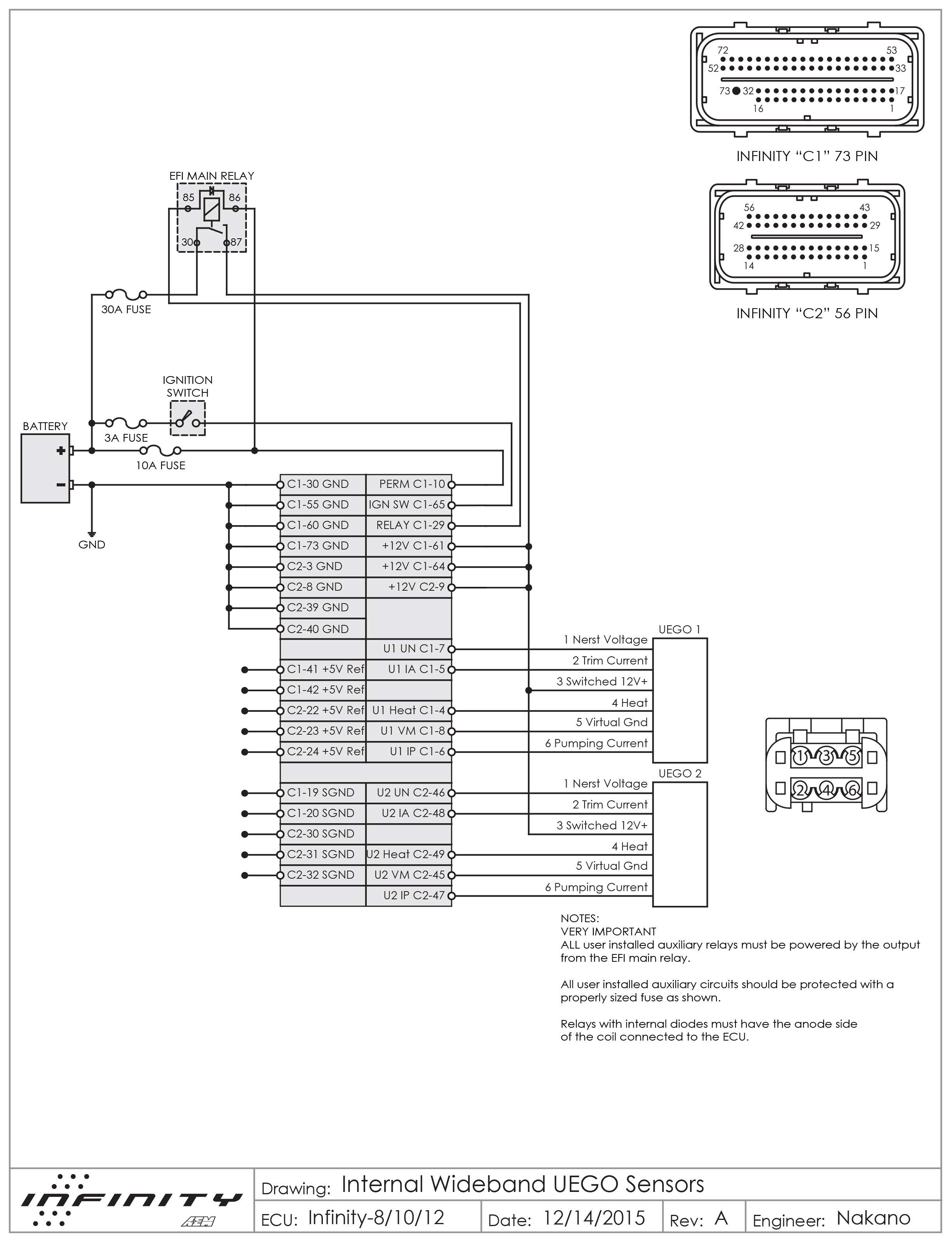
Aem wideband wiring diagram. The wire will come through behind the glovebox area. My AEM UEGO gauge's 12v ACC source is tapped into the radio harness and grounded nearby. The 5v output wire for logging (also conveniently a solid white wire) will connect to the yellow wire that we just routed behind the radio. Jun 15, 2021 · Aem Uego Wideband Wiring Honda Tech Forum Discussion. 30 0300 x series uego gauge how to logging wideband afr via serial aem 2310 inline owner manual 5143 analog e85 4900 failsafe wiring diagram product manuals air fuel ratio through the ac or canbus instruction pdf wide band with mspnp2 apex stangnet 2067 wifi egt wires from tie power fc datalogit and channel controller honda tech a f ... Jun 18, 2020 · Aem Wideband O2 Sensor Wiring Diagram– wiring diagram is a simplified usual pictorial representation of an electrical circuit. It shows the components of the circuit as simplified shapes, and the aptitude and signal associates with the devices. I am wiring a bosch lsu 4.2 wideband to an aem infinity 508. The bosch wideband has 5 wires on a 6 plug connector. But there are 6 wires that go to the "ecu" side of the plug, and AEM says it has to be wired that way. Can anyone explain whats happening inside the plug that requires this extra wire?
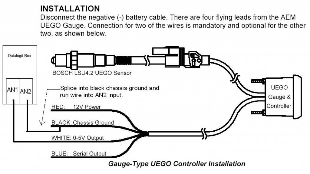
Hey all, trying to hook up my AEM UEGO wideband into my buddies FlashScan V2 so we can log the wideband's output. I've read a bit and wanted to verify before making cables/blowing anything up. Alright, so, from the AEM gauge, I'm going to run the blue cable (serial output "Connects to a RS-232 com port for hyper-terminal data logging") to pin 2 on a DB9 serial connector. Part Number 30-5130 Analog Wideband Air/Fuel Ratio Gauge Figure 1. Wiring Schematic AEM Gauge-Type UEGO Controller Parts 1 x 35-5130(B/W) UEGO Gauge Assembly aem wideband wiring diagram - You will want a comprehensive, expert, and easy to comprehend Wiring Diagram. With this sort of an illustrative manual, you will be able to troubleshoot, avoid, and complete your projects with ease. Aem 30 5143 Analog E85 Wideband Uego Gauge Afr Instructions Manualzz. Aem 30 2310 Inline Wideband Uego Controller Instructions Manualzz. Product Manuals Wiring Diagram Electrical Wires Cable Installation Boost Gauge Angle Text Png Pngwing. Aem 30 2340 N 4 Channel Wideband Uego Afr Controller Instructions Manualzz.
Go to options , settings. select use external instead of stock wideband. select the wideband senor you are using. If your using AEM there is no setting for it , so use PLX setting. Once car is running and your reading the wideband. Fill in the voltage offset box in the same place to make Kmanager read the same EXACTLY as the gauge for the wideband. AEM 30-0310 wideband controller. USB-Serial adapter (labeled FTDI FT232RL on the female serial plug) Male-male serial cable cut in half. AEM's instructions say to connect pin 2 to the blue wire from the wideband controller and pin 5 to ground. I used a continuity tester to map the wire colors to the pins on the male serial cable. AEM Electronics has been at the forefront of wideband performance since their very first AEM UEGO gauge. If you own the original gauge, take a look here at our How To for further installation instructions on a Honda Fit. And as great as the original is, we absolutely love the new AEM Failsafe UEGO Wideband Gauge.. Delivering the same level of excellence and accuracy found in the earlier models ... Aem 30 2310 Inline Wideband Uego Controller Instructions Manualzz. Aem Analog Wideband Air Fuel Ratio Gauge Installation Instruction. Product Manuals Wiring Diagram Electrical Wires Cable Installation Boost Gauge Angle Text Png Pngwing. Wiring Aem X Series Wideband Canbus To Ms3 Pnp Pro 2001 2005 Miata Turbo Forum Boost Cars Acquire Cats.
(for AEM EMS see page 4) Serial Output (optional) The serial output can be used for data logging when an EFI system is not accessible. To run the data stream, a RS-232 (DB-9) Female Receptacle shall be purchased. 12345 6789 Wire View of RS-232 (DB-9) Male Plug Two wires need to be connected to a RS-232 serial port. The BLUE wire from the AEM
The AEM X-Series Inline Wideband Controller features a low-profile weather resistant enclosure with interface options suitable for most data loggers and ECUs. The AEM inline controller is ideal for all vehicles including carbureted ... Wiring Installation Diagram Important Notes on Wiring · Route harnesses carefully to avoid chafing or undue ...
AEM Wideband Failsafe is an advanced safety device that allows the end user to closely monitor the ... Installation Diagram . Page 5 Installation 1. Disconnect the negative battery cable. ... 4. Next, the UEGO sensor 8-pin wiring harness should be routed to the oxygen sensor bung. Pin Color Description 1 N/C N/C
Wiring Installation Diagram Gauge Connections The X-Series UEGO gauge is supplied with a Power/IO wiring harness (A) and a UEGO sensor harness (B); the harnesses are connected to the gauge as shown below. The UEGO sensor harness simply needs to be routed to the UEGO sensor whereas the Power/IO harness will require further integration into the ...
AEM X-series to pro link for analog input wiring. Hey guys I'm new to tuning and the forum here. I ordered the Pro link set for my MPVI2 unit and have an AEM X-series wideband. I'm wanting to wire the AEM to the pro link so that I can log wideband data from cars that don't run on a CANBUS system. I was thinking about taking the pin out of the ...
30-0334 X-Series Wideband UEGO AFR Gauge w/ OBD CAN Integration Wiring Installation Diagram Gauge Connections The X-Series UEGO gauge is supplied with a Power/IO wiring harness (A) and a UEGO sensor harness (B); the harnesses are connected to the gauge as shown below. The UEGO sensor harness simply needs to be routed to the UEGO sensor
There are many different ways to wire in a wideband oxygen sensor. From our experience, many methods cause poor wideband sensor performance due to electrical interference or insufficient grounds.The following method for wiring in a wideband oxygen sensor to a vehicle equipped with an OBD1 ECU is our recommendataion for
Aem wideband wiring diagram wiring diagram is a simplified up to standard pictorial representation of an electrical circuit it shows the components of the circuit as simplified shapes and the capability and signal associates along with the devices. 10 0300 2017a ep e rf oma ncl t i s 30 0300 x series uego gauge wiring installation diagram gauge ...
(Skip this section if you are not connecting the product to an AEM EMS.) If the AEM UEGO gauge is to be connected to an AEM EMS, the UEGO gauge's WHITE Analog Output wire shall be connected to an EMS Lambda input. Locating a suitable Lambda input channel can be done using the Application Notes provided with the EMS.
Wiring Schematic. AEM Gauge -Type UEGO Controller Parts. 1 x (B/W) UEGO Gauge Assembly. Aem 35 Wiring Diagram. welcome to my blog here I will show you a little more what you are looking for Aem 35 Wiring Diagram below there are.Find best value and selection for your AEM Wideband O2 Air Fuel UEGO Gauge Only 35 Tested Works Great search on eBay.
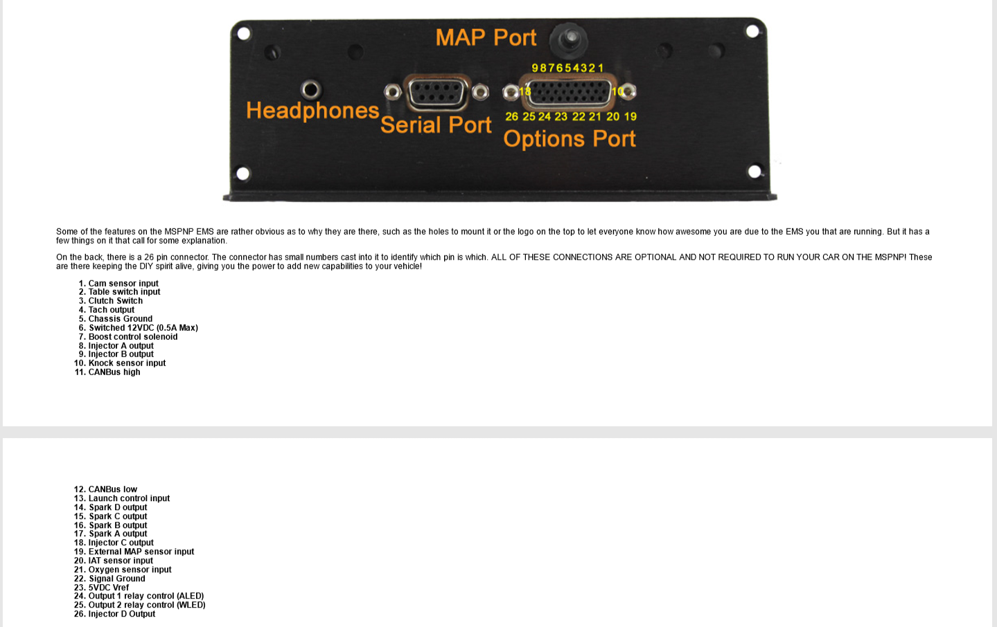
2. Wire the wideband's ground wire to a clean ground source (battery). 3. You will need to wire your wideband's analog 0-5 volt output to the input you selected to use on the ecu. (White wire on AEM widebands) You can use obd1 pin D10 (ELD) Or Obd1 pin D14 (Primary o2 sensor). When using an innovate mtx-l the signal wire is yellow.
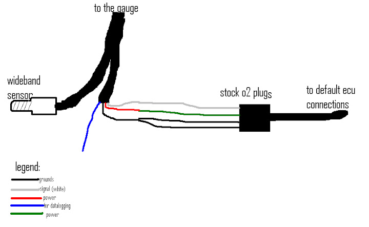
The AEM wideband system consists of the sensor and its loom, ... ECU Lambda Signal Wire. The white signal wire from the AEM gauge is fed into the engine bay, the same as the earth wire. Attaching it to the original narrow-band signal wire will connect it to the correct pin on the ECU. ... the AEM instruction manual gives a diagram of the ...
16" WIDEBAND AIR/FUEL RATIO ® MONITOR - ANALOG 2650-1469-00 Rev. B Installation 1. Disconnect the negative (-) battery cable. 2. Gauge can be mounted in a 21⁄ 16". hole with brackets supplied. Gauge can also be mounted in Auto Meter Mounting Cup, or in Auto Meter Gauge Works Pods. 3. Wire gauge as shown. Red Wire (Power):
Feb 02, 2021 · Aem Wideband Wiring Diagram – aem uego sensor wiring diagram, aem uego wideband wiring diagram, aem uego wiring diagram, Every electrical structure is made up of various different pieces. Each part ought to be placed and connected with other parts in particular manner.











0 Response to "37 aem wideband wiring diagram"
Post a Comment