41 reversing contactor wiring diagram
Wiring Diagrams & Standard Electrical Schematics Access Our Easy-to-Use Diagrams, When You Need Them. Standard Contactor & Starter Drawings. CA7/CA6 Full Voltage Non-Reversing Contactors. Drawing # Description PDF File DWG File; WS-100-01: CA7-9..97 w/ D7 Pilot Device Kits, Three Phase: WS-100-11A: CB7-9..97 w/ Local Devices, Single Phase: ... 2015 - A detailed look at the design and application of reversing contactors. ... Wiring, Electrical Symbols, Electrical Projects, Electrical Diagram, ...
If you look at the wiring diagram on the reversing kit documentation, it looks just like the diagram we had earlier -- doesn't it? Except now, we don't have to add any aux contactors or do any of the wiring ourselves. You do need to make sure you get contactors with a normally CLOSED aux contact.

Reversing contactor wiring diagram
"WIRING DIAGRAMS" vs "LINE DIAGRAMS" Most of the diagrams in this book are shown in two ways. There is a "wiring diagram" and adjacent to it a "line diagram." Line diagrams are included because their use is becoming more widespread and we believe it is advantageous to learn to use them. Dec 11, 2021 · Single phase reversing contactor wiring diagram. Single phase motor wiring diagram forward reverse You will want an extensive professional and easy to know Wiring Diagram. The above diagram is a complete method of single phase motor wiring with circuit breaker and contactor. In the above one phase motor wiring i first connect a 2 pole circuit ... Wiring diagrams, sometimes called "main" or "construc-tion" diagrams, show the actual connection points for the wires to the components and terminals of the controller. They show the relative location of the components. They can be used as a guide when wiring the controller. Figure 1 is a typical wiring diagram for a three-phase mag-
Reversing contactor wiring diagram. Sep 16, 2019 · The forward reverse motor control is used in a system where forward and backward or upward and downward movement in the operation is needed. Forward and Reve... Reversing Contactor Definition Advantages And Connection Diagrams. Electrical Electronic Systems Forward Reverse 3 Phase Ac Motor Control Wiring Diagram Star Delta Main Circuit 1 Mcb Mini Circut Breaker 2 Fc. Reversing Contactor Assembly Ac Coil External Interlock With Power And Auxiliary Wiring 9a Ac3 In 4kw Voltage 230vac 50 60hz Lovato ... I am trying to wire a single phase motor to a reversing contactor. the incoming power is 115VAC, my control circut is 24VAC. i understand the control part of it but what im trying to figure out is how to wire the motor to the contactor so as to reverse direction of the motor. the motor has 6 leads. a picture is attached. i do know that T5 and T8 need to swap to reverse direction, but im lost ... 24 Volt 250 Amp Motor Reversing Contactor 24 Volt DC 250 Amp motor reversing contactor. Coil power consumption 13 Watts. Has no-load rated make or break contacts so it needs to be used with a speed controller and the vehicle should be stopped before switching between forward, park, and reverse directions. Applies electronic braking to the motor when the switch is in the park position which ...
120v Ac Capacitor Motor Reversing Switch Wiring Diagram. To complete a single phase motor direction change, you will need to motors go in forward and reverse depending on their wiring and the resulting magnetic field. ask that they not flip any breakers or switches until you are finished. To reverse rotation on a single phase capacitor start ... Reversing Contactor (White Rogers 586) Diagram for Series Motors.pdf. Alltrax AXE Reverse With Plug Brake Wire Diagram. Doc100-048-B_DWG-AXE-PlugBrk-Rev-wire-dia.pdf. Winch Motor With DC88 Reversing Contactor. DC88WiringDiagram.pdf. General Reversing Contactor Wiring Diagram. ReversingContactorDiagram.pdf. Reversing Contactor Position the diode so that the stripe and red heat shrink is on the switch side of the circuit, or hot side. The picture above shows one side of a reversing contactor. Repeat on the other side. Stripe Red Black Red Black SW202 / SW182 & DC182 Wiring Diagram For Series Motors & Permanent Magnet Brushed Motors S1 S2 S1 S2 M- M ... of the diodes (cathode end/white band) connect a green 18 gauge wire and connect to the green contactor wire. From the other diode (cathode/white band) connect a orange wire to the contactor orange wire. Use a connector large enough to accommodate both orange wire or both green wires. See inset on diagram.
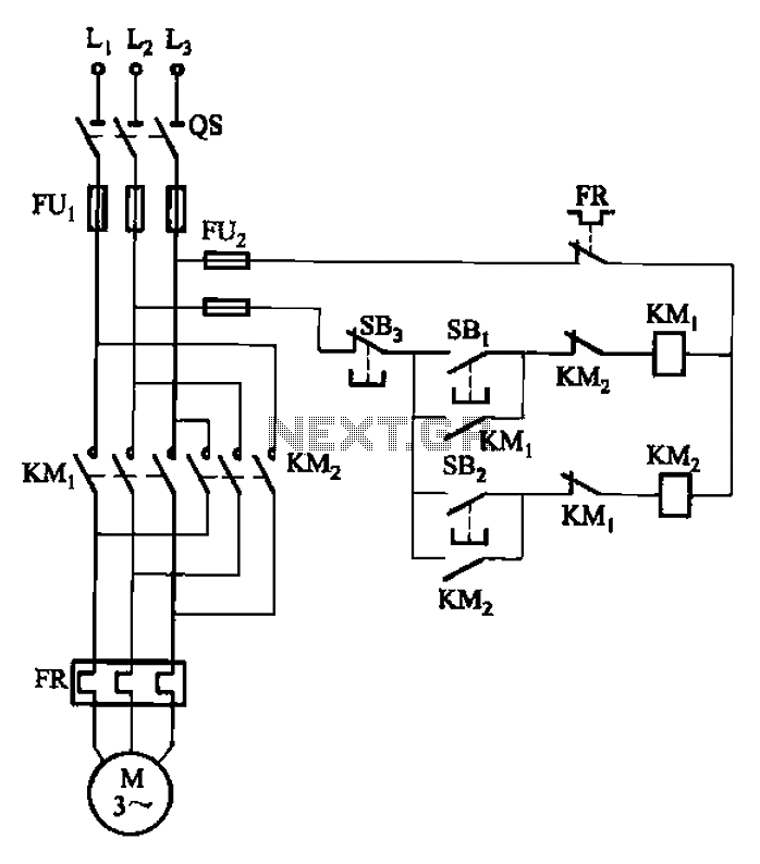
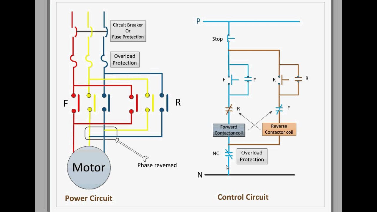
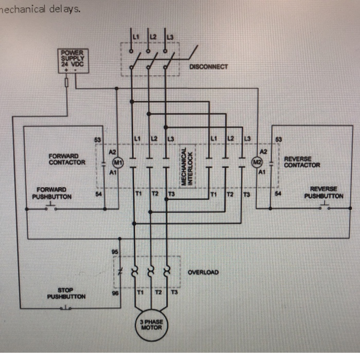
The interlock device will prevent the contactors from turning on at the same time. Interlock can be placed in between two contactors. Below you can see the power and control circuit connection diagrams of reversing contactors. Let’s explain how they work: 1-Wire up the first and second contactor’s coils to separate pushbuttons. Our reversing (change-over) contactor kit includes: Reversing (Change-over) Contactor - select Voltage, Contactor Coil Spike Supression Diodes, Heat Shrink Tubing, SPDT Rocker Switch and Housing, Quick Disconnect Spade Connectors, and Choice of Tinned Copper Terminal Lugs. Heavy gauge cable is optoinal. Small gauge wire not included. A detailed look at the design and application of reversing contactors. Applies to everything! Interlocking devices included. This is some of my best work yet. The reverse contactor coil energized and three phase induction motor runs in the reverse direction. In the diagram I connect the incoming three phase supply L1 L2 L3 to the MCCB circuit breaker molded case circuit breaker. As soon as. 39 recent star delta forward reverse wiring diagram pdf through the thousands of photos on the web in relation to.
Start reversing contactor interlock control circuit under ...
Mar 27, 2020 · Reversing Contactor Wiring Diagram 230v Motor Wiring Diagram Free Download Schematic Wiring Diagram. Reversing Contactor Wiring Diagram – wiring diagram is a simplified satisfactory pictorial representation of an electrical circuit. It shows the components of the circuit as simplified shapes, and the skill and signal friends amid the devices.
PLC Implementation Of Forward/Reverse Motor Circuit With ...
May 29, 2019 · Single phase reversing contactor wiring diagram. Why 3 phase ac instead of single phase. In the above one phase motor wiring i first connect a 2 pole circuit breaker and after that i connect the supply to motor starter and then i do cont actor coil wiring with normally close push button switch and normally open push button switch and in last i do connection …

Circuit wiring diagram of contactor interlock reversing ...
Contactor wiring diagram pdf. IEC Contactors 41-42 IEC Contactors and Auxiliary Contact Blocks 41 Input Modules and Reversing Contactors 42 Type S. I know how relays work in general. You will be in a position to understand exactly once the assignments ought to be completed that makes it much simpler to suit your needs to correctly manage your ...

Type of Contactor for Direction Change of Single-Phase IM ...
Reversing Contactors Open Type Version Wiring diagrams VOA 9-30M … VOA 40-30M reversing contactors, factory assembled With VM 5-1 mechanical interlocking, electrical interlocking by built-in auxiliary contacts. Power circuit Remote control For the hold-in contacts (13-14) of the KM1 and KM2 contactors, supply separately 2 x CA 5-10

Electrical and Electronics Engineering: Full voltage ...
Wiring Diagrams ww introduction This booklet has been prepared as a guide to some of the useful ways Allen-Bradley’s manual and magnetic across-the-line starters may be applied. It will also serve as a useful The Bulletin RS manual reversing starters and the.Google Answers: I need to know which contactor or starter to use to control my ...
Definite Purpose Control
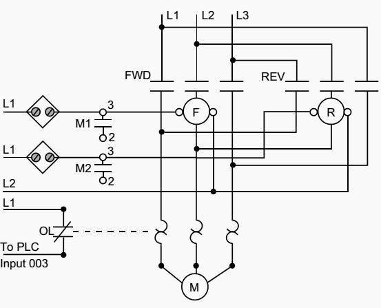
Change-over contactors are multiple contactors bound together that allow the user to change the polarity of the voltage going to the motor thus reversing direction. It works exactly the same as the manual F/R switch, except that it uses coil drive contactors. See the installation drawings for how to wire up a change-over contactor.
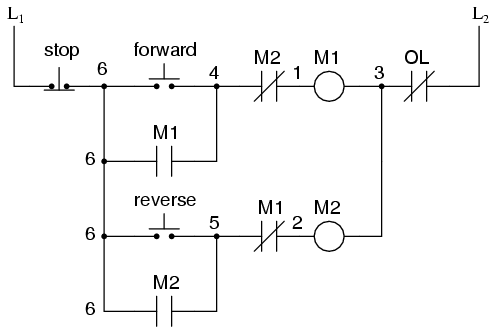
Control circuit for forward and reverse motor
Reversing Control Circuit ... When designing the control schematic for forward / reverse circuits, we start with the standard three-wire circuit , add a second ...
575 Series - Motor Reversing Contactors On Struthers-Dunn
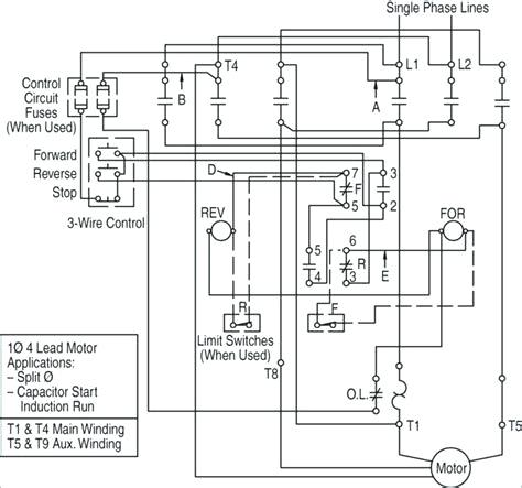
I have a customer with a single phase, dual voltage (115/230V) motor. He has a Siemens 43CP12FB reversing contactor and a 3UB8823-4DW2 overload. With the supplied wiring diagrams and/or searching on Siemens website, I cannot find out how this should wired. His motor has 6 leads, and to reverse direction, L1 & L2 are swapped for T5 & T8.

REVERSING CONTACTOR ASSEMBLY, AC COIL, EXTERNAL INTERLOCK ...
Jan 18, 2022 · Relay and contactor wiring diagram.Single Pole Contactor Relay Wiring Diagram 240v Single pole means that it can only control a single circuit and single throw means that there are only two positions the switch can be in one on and one off state mechanical relays do not The esd5 series is an accurate solid state delayed interval timer it offers a 1a steady 10a …

Interlocking Methods for Reversing Control (Basic Control ...
3: Simplified GN0 Motor-Reversing SSR wiring diagram As can be seen from figure 3 above, two of the three phases are wired through the GN0 and the third phase is connected directly to the motor. When a logic signal is applied to the "forward" terminal, the GN0 switches L1 and L2 directly to .
How single motor can be ON by two contactor coil - PLCS.net ...
wiring time Accessible terminals for easy wiring. Optional fingerproof shields available to prevent electrical shock Top located coil terminals convenient and readily accessible. 45 mm contactor magnet coils have three terminals, permitting either top or diagonal wiring—easy to replace European or U.S. style starters or contactors
What are the functions of KM1 and KM3 in the ATS48 soft ...
Input Modules and Reversing Contactors 42 Type S AC Magnetic Starters.....43-50 Class 8536 43-50 8538 and 8539 45,49 1-Phase, Size 00 to 3 43 2-Phase and 3-Phase, Size 00 to 5 44 3-Phase, Size 6 45 3-Phase, Size 7 46 3-Phase Additions and Special Features 47-50 ... WIRING DIAGRAM. M A1 A2 M .

ATO 12 Volt DC Contactor, 2 Pole 200A - - Amazon.com
When applying these diagrams, it is well to. Jun 11, · I am trying to wire a single phase motor to a reversing contactor. the incoming power is VAC, my control circut is 24VAC. i understand the control part of it but what im trying to figure out is how to wire the motor to the contactor so as to reverse direction of the motor.

Reversing 6-lead single phase dual voltage motor with forward ...
Aug 23, 2008. #10. To reverse a single phase motor, the start winding is reversed, which according to the information given is T5 andT8. I would give you a drawing, but my drawing program uses too many bytes to post on this forum. Two three pole contactors are used, which are mechanically and electrically interlocked.
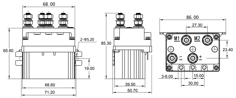
100A DC Motor Reversing Contactor, 12V/24V/48V, 2NO & 2NC
Wiring diagrams, sometimes called "main" or "construc-tion" diagrams, show the actual connection points for the wires to the components and terminals of the controller. They show the relative location of the components. They can be used as a guide when wiring the controller. Figure 1 is a typical wiring diagram for a three-phase mag-

Forward/Reverse Control Circuits – Basic Motor Control
Dec 11, 2021 · Single phase reversing contactor wiring diagram. Single phase motor wiring diagram forward reverse You will want an extensive professional and easy to know Wiring Diagram. The above diagram is a complete method of single phase motor wiring with circuit breaker and contactor. In the above one phase motor wiring i first connect a 2 pole circuit ...
Type of Contactor for Direction Change of Single-Phase IM ...
"WIRING DIAGRAMS" vs "LINE DIAGRAMS" Most of the diagrams in this book are shown in two ways. There is a "wiring diagram" and adjacent to it a "line diagram." Line diagrams are included because their use is becoming more widespread and we believe it is advantageous to learn to use them.
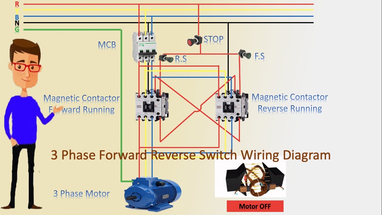
3 Phase Forward Reverse Switch Wiring Diagram | contactor wiring | Motor Wiring

RIGID CONNECTING KITS FOR THREE-POLE REVERSING CONTACTOR ...

3-pole contactors and overload relays for motor starting ...
Full Voltage Reversing Starter

Motor Forward Reverse Wiring Diagram | Elec Eng World ...

400A Reversing Contactor DPDT | Electric Car Parts Co

Forward Reverse Motor Control Diagram For 3 Phase Motor
Solved Given the attached schematic for a reversing | Chegg.com

Practical Machinist - Largest Manufacturing Technology Forum ...

wiring up forward reverse motor starter with electric ...

36v txt sr48500 sw202 7126 motor. No reverse intermittent ...
3RA23158XB301BB4
Coffing UJC.qxd
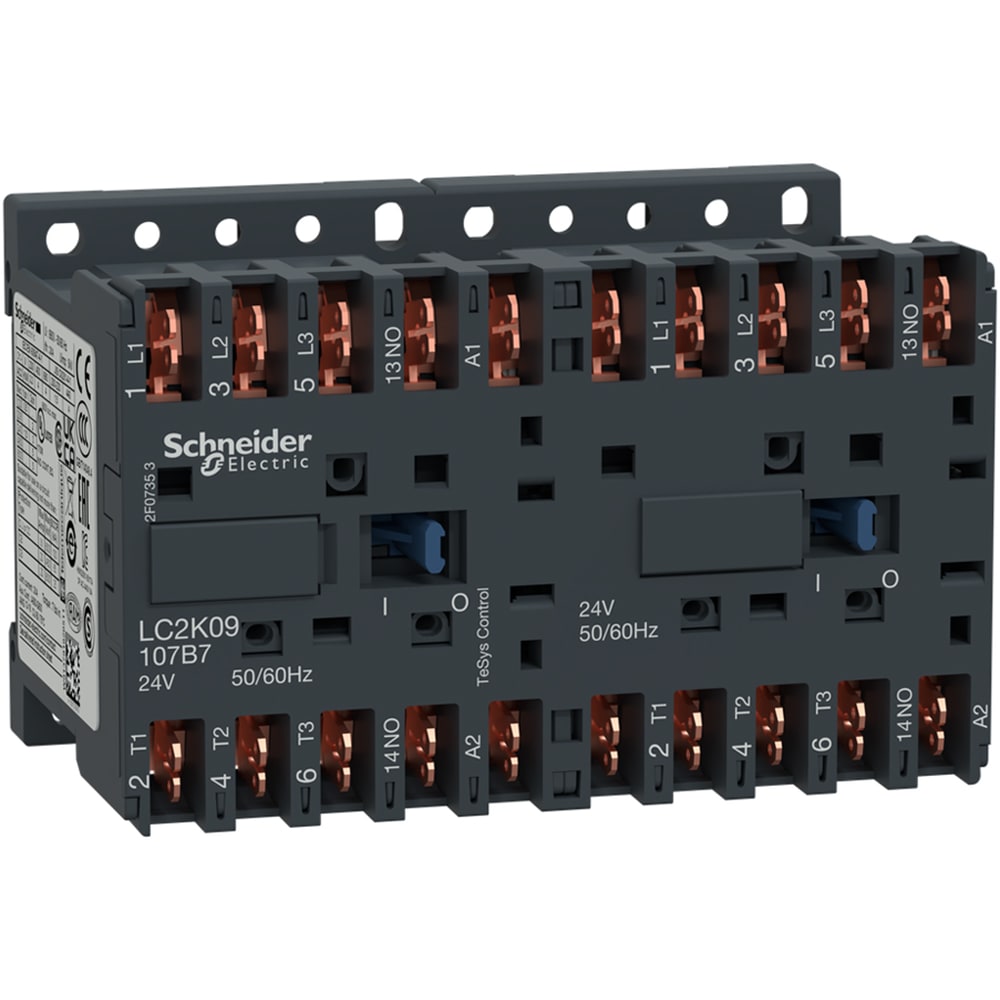
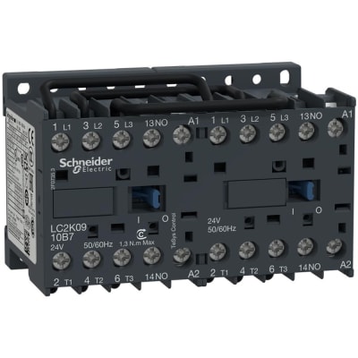
LC2K09107B7
Reversing contactors

Forward Reverse Starter With Timer 3 Phase Motor Wiring Diagram
Square D Wiring Diagrams for Contactors, Starters, Relays ...

Interlocking Methods for Reversing Control (Basic Control ...
LC2K0910B7
YJLMT Series
Wiring of a contactor LC1D091o to a daynight switch | DIY ...

200A DC Reversing Contactor, 2 pole, 12V/24V/48V

SW182 Type Motor Reversing DC Contactor

Pin on Motor 3 fase
0 Response to "41 reversing contactor wiring diagram"
Post a Comment