42 mechanically held contactor wiring diagram
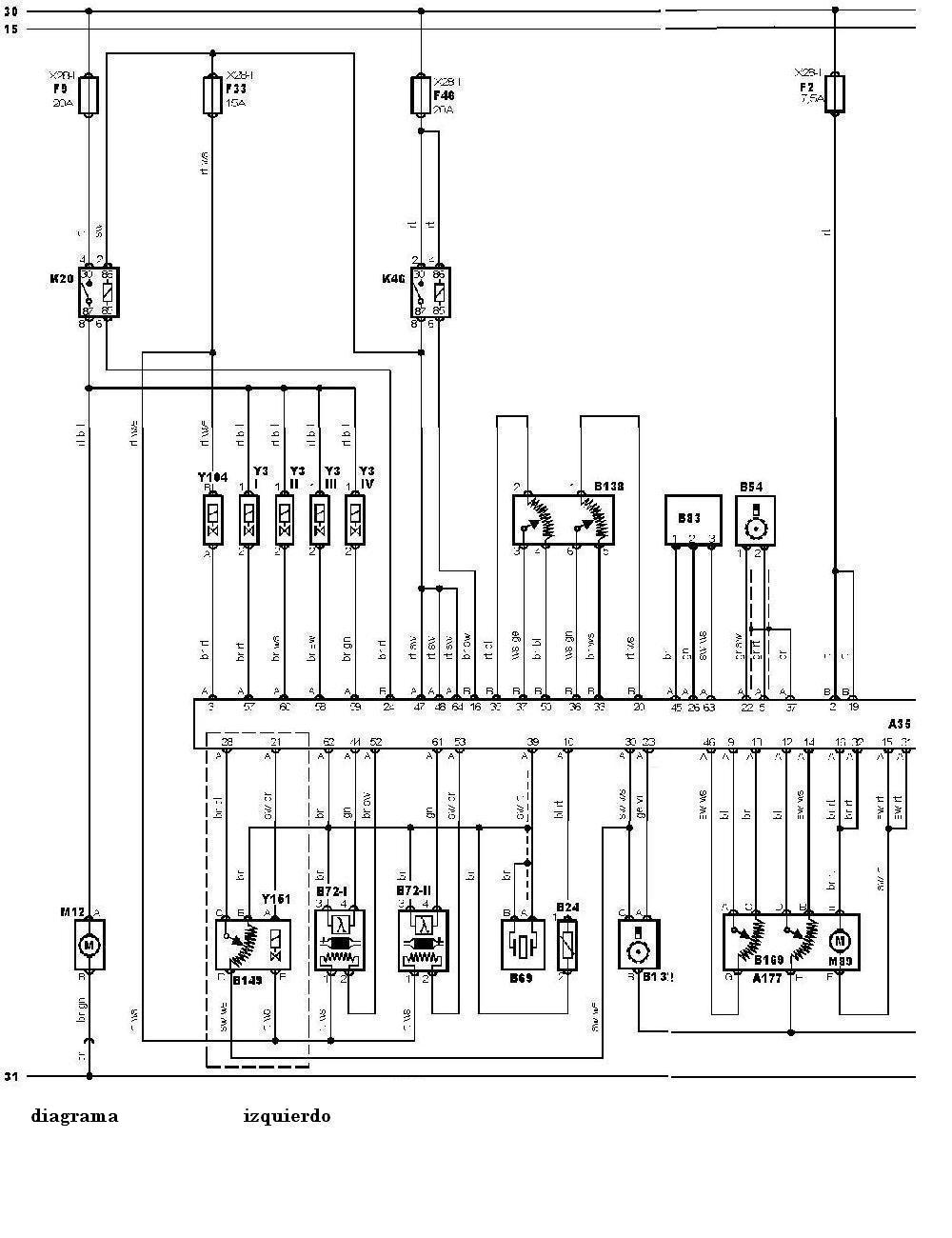
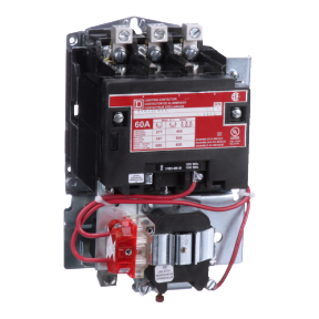
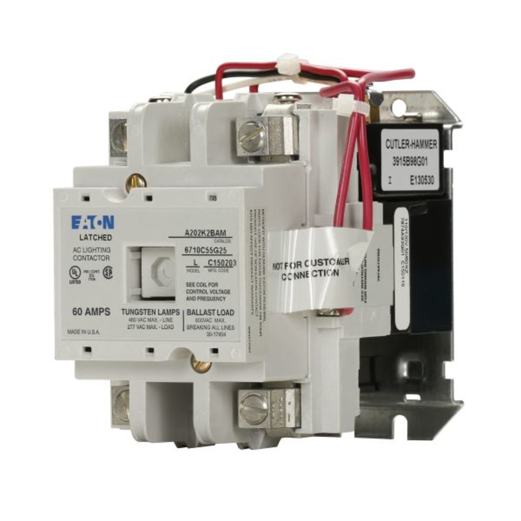
CR463M mechanically held contactors A mechanical latch with a 2- or 3-wire electronic control module delivers reliable performance and protection from such application abnormalities as line noise, leakage currents from controller outputs, or short repetitive commands burst from faulty controllers. Variety of mechanically held lighting contactor wiring diagram. A wiring diagram is a simplified standard pictorial depiction of an electric circuit. It shows the elements of the circuit as simplified forms, as well as the power and also signal connections in between the gadgets.
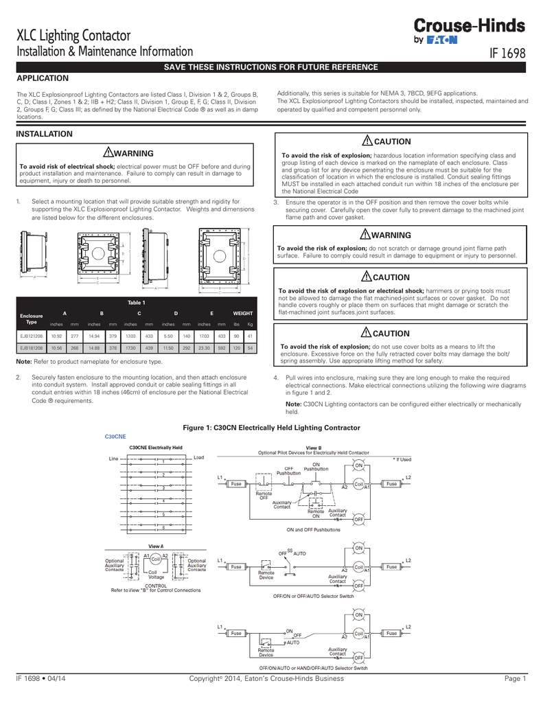
Typical Wiring Diagrams. Table a: 2-WIRE connection diagram electronic module. Hand off auto. Table b: optional wiring and pilot devices for mechanically-held contactor, 2-WIRE control.

Mechanically held contactor wiring diagram
2 wire connection diagram 500lg mechanically held 3 wire optional aux optional aux. The mechanically held operation ensures that the contactor will not switch. 8903lx mechanically held lighting contactor 12p 12 no 30 a 600 v 110120 v 5060 hz. Kindle File Format Mechanically Held Contactor Wiring Diagram. However below, taking into account you visit this web page, it will be suitably extremely easy to acquire as competently as download lead Mechanically Held Contactor Wiring Diagram. Read the particular schematic like a new roadmap. I print out the schematic plus highlight the circuit I'm diagnosing in order to make sure Im staying on the particular path. Mechanically Held Lighting Contactor Wiring Diagram Source: i.pinimg.com.
Mechanically held contactor wiring diagram. The aircraft’s wiring diagram will show all the installed electrical components in the circuit as well as the wire numbers. One of the first things to check in this case is the integrity of the field wire, especially right at the F1 terminal. 33 mechanically held contactor wiring diagram free source truck lite led tail light for schematics cooper lighting motion sensor instructions style warning cr460 series revision 11 021402 1986 toyota fuel sender vga diau tiralarc bretagne fr xlc tercel ct90 tukune jeanjaures37 selecting effective control... WIRING DIAGRAM A wiring diagram shows, as closely as possible The selector switch disconnects the holding circuit contact and jogging may be accomplished by pressing the Start push button. Mechanically Latched Contactors and Medium Voltage Motor Controllers Class 8196 and 8198. Jan 14, 2014 · Wiring Connection Diagrams Basic Blueprint Reading Wiring 96 (connection) diagram – a diagram that shows the connection of an installation or its component devices or parts. This type of wiring diagram shows, as closely as possible, the actual location of each component in a circuit, including the control circuit and the power circuit.
Bul 500lg lighting contactor mechanically and electrically held author. Optional wiring and pilot devices for mechanically held cont... This book contains examples of control circuits, motor starting switches, and wiring diagrams for ac manual starters, drum switches, starters, contactors, relays, limit switches, and lighting contactors. Mechanically Held Contactor Wiring Diagram Mechanically Held. View and download mitsubishi electric rd77ms2 user manual online. Eaton Lighting Contactor Wiring Diagram Best Of Square D. Contactor Wiring Diagram Magnetic Single Phase Mechanically Held For. Low input va permits long wire runs verifies contact status and has built in delays that minimize excessively frequent signals from faulty...
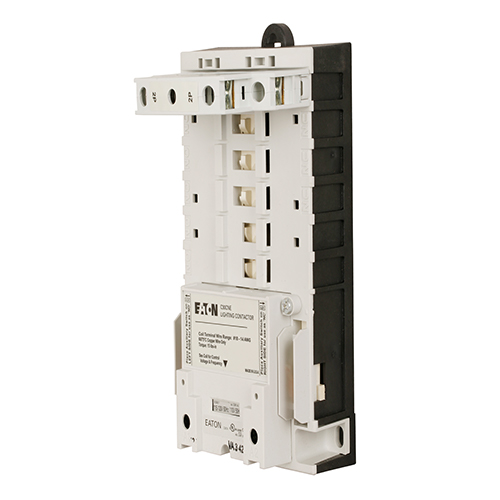
Wiring Diagram 29 Lighting Contactor Wiring Diagram With. Wiring Diagram For Contactor And Photocell. There is a massive need for tutorials regarding how to make Cat5 and Cat5e patch cables for DIYs. Wiring Diagram For Mechanically Held Contactor. 7 hours ago A wiring diagram is a form of schematic which uses abstract pictorial symbols to exhibit every one of the interconnections of components inside a system. Rd77ms2 controller pdf manual download. Description : Contactor And Photocell Wiring Diagram Photocell Controlled for Mechanically Held Lighting Contactor Wiring Diagram, image size 733 X 768 px, and to view image details please click the image. Three-Wire Mechanically Held Lighting Contactors— Standard Assembled Forms, continued. Number of Poles. Catalog NO NC Number 123. A mechanically held contactor with a two-wire control module uses 1NC auxiliary contact as standard for the control wiring circuit.
Print the electrical wiring diagram off and use highlighters to trace the signal. When you use your finger or even stick to the circuit with your eyes, it may be easy to mistrace the circuit. A single trick that We use is to printing exactly the same wiring picture off twice.
Unique Wiring Diagram For Mechanically Held Lighting. Square D Lighting Contactor. There are several electrical Mechanically Held Lighting Contactor Wiring Diagram s installed as part of your properties.
Lighting contactor wiring diagram with photocell. Timer And Contactor R Relay Diagram. It shows the components of the circuit as simplified Electrically Held to Mechanical Latch Contactor Retrofit Instructions 5 1502-IN001-EN-P -XQH Install the Mechanically Latched Auxiliary Contact Assembly 1.
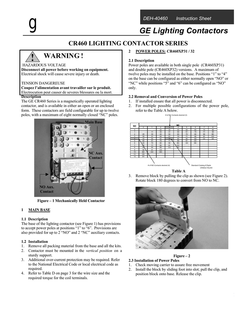
Mechanically Held 3-wire Control Module. (Key Removal All Positions). Enclosure accessory kits contain accessory and complete installation wiring CR436M Mechanically Held Contactors. Follow the diagram and tables below to select the options and corresponding catalog number digits for your...
Unique Wiring Diagram For Mechanically Held Lighting Contactor. It also ensures the removal of coil from the circuit for noise free operation and the elimination of all coil losses. Image Result For Contactor Timer Diagram Latches Wire. A maximum of 12 poles may be installed on the base.
› Get more: Mechanically held lighting contactorShow All. wiring diagram mechanically held contactor. Excel. Details: Diagram Square D Contactor Wiring Full Version Hd Quality Psychediagramme Fondoifcnetflix It. Isimet E Series Enclosure.
2018 Full Book IET Wiring Regulations - Free ebook download as PDF File (.pdf), Text File (.txt) or read book online for free. BS 7671-2018 IEC Wiring Regulations
Photocell Lighting Contactor Wiring Diagram Wiring Diagram. 37 10 G G 37 Mechanically Held. Volume 10 Tab 4.
7th Edition IEE Wiring Regulations: Design and Verification of Electrical Installations. Asım Kurt. Download Download PDF. Full PDF Package Download Full PDF Package. This Paper. A short summary of this paper. 19 Full PDFs related to this paper. Read Paper.
Two wire mechanically held lighting contactors standard assembled forms the standard assembled forms in tables on pages v5 t6 6 and v5 t6 7 are A wiring diagram is a simplified standard pictorial depiction of an electric circuit. Electrically and mechanically held lighting contactor specifications...
intermatic contactor wiring diagram wiring diagram database. Architectural wiring diagrams accomplish the approximate locations and interconnections of receptacles, lighting, and Related Posts of "Square D Mechanically Held Contactor Wiring Diagram". 1964 El Camino Wiring Diagram.
Mechanically latched relay - maintains state even when power removed. Has two coils (operate, reset) Typical wiring MECH. pera ese LOAD LOAD Typical Applications Reversing Motor starters. Reclose Relay Cut-out et438b-7.pptx COIL COIL Inputs A and B set the output contacts E and reset then respectively. This give toggle action that "remembers ...
A line (ladder) diagram is a diagram that shows the logic of an electrical circuit or system using standard symbols. A line diagram is used to show the relationship between circuits and their components but not the actual location of the components. Line diagrams provide a fast, easy understanding of the connections and use of components.
A wiring diagram normally offers details regarding the relative setting and setup of tools as well as terminals on the tools, to aid in structure or Dimension: 990 x 815. Collection of mechanically held lighting contactor wiring diagram. Click on the image to enlarge, and then save it to your computer...
Subsequent diagrams is reasonably simple, but using it inside the opportunity of how the device operates is a new different matter. I print the schematic plus highlight the signal I'm diagnosing to make sure I am staying on the particular path. Mechanically Held Lighting Contactor Wiring...
page 179 section 7 part 7 electrical data 8kw 2010 air-cooled hsb wiring diagram – drawing 0h6912-b ol panel customer connect area neut 240v generator output to transfer switch contactor legend ba - brush assembly c1 - alternator connect - circuit breaker, main output l1: green = system ready gnd - ground hto - high temperature switch...
Class clm lighting contactor mechanically held. Optional wiring and pilot devices for mechanically held contactor 3 wire control on off pus...
30 Mechanically Held Contactor Wiring Diagram - Wiring from static-assets.imageservice.cloud. The contactor is latched closed when its set coil is energised or opened by the trip coil to unlatch it when required to. 13.8 main feeder cables for supplying power to elevators shall be installed outside...
GLOSSARY Contactors/Relays Location Function Diagram Parts Breakdown Contactor Panel Emergency Disconnect Page 246 Page 34 (1) Page 247 Page 250 Page 254 Page 255 Page 258 K1-A Platform Load Tray Lower Page 255 Page 256 K1-B Platform Load Tray Raise Page 255 Page 256 Hydraulic Unit...
Poles for Type LX mechanically held contactors. Since the coil burden is not directly on the control circuit longer wire runs between lighting control and contactor are possible. Contactor Timer بحث Google Wiring Diagram Timer Diagram from www.pinterest.com.
...mechanically held relay,square d mechanically held lighting contactor,why are mechanically held relays energy saving devices, published by. To find out all graphics within Mechanically Held Lighting Contactor Wiring Diagram photos gallery you need to follow this specific web page link.
Read the particular schematic like a new roadmap. I print out the schematic plus highlight the circuit I'm diagnosing in order to make sure Im staying on the particular path. Mechanically Held Lighting Contactor Wiring Diagram Source: i.pinimg.com.
Kindle File Format Mechanically Held Contactor Wiring Diagram. However below, taking into account you visit this web page, it will be suitably extremely easy to acquire as competently as download lead Mechanically Held Contactor Wiring Diagram.
2 wire connection diagram 500lg mechanically held 3 wire optional aux optional aux. The mechanically held operation ensures that the contactor will not switch. 8903lx mechanically held lighting contactor 12p 12 no 30 a 600 v 110120 v 5060 hz.











0 Response to "42 mechanically held contactor wiring diagram"
Post a Comment