37 how to draw a timing diagram
Janis Osis, Uldis Donins, in Topological UML Modeling, 2017. 1.2.2.7 Timing Diagram. Timing diagram is used to show interactions when a primary purpose of the diagram is to reason about time; it focuses on conditions changing within and among lifelines along a linear time axis. Timing diagram is a special form of a sequence diagram. The most notable graphical difference between timing diagram ... Hello James, Visio 2010 does support hardware timing diagrams. To use it for this purpose: Go to Start Menu > Vision 2010 > Engineering > Parts and assembly drawing > create. Templates for hardware timing are not available on Microsoft but they can be found online from third parties, though I would advise some caution.
The timing diagram of the binary ripple counter clearly explains the operation. Timing Diagram of Binary Ripple Counter. From the timing diagram, we can observe that Q0 changes state only during the negative edge of the applied clock. Initially, the flip flop is at state 0. Flip-flop stays in the state until the applied clock goes from 1 to 0.

How to draw a timing diagram
Creating timing diagram. Perform the steps below to create a UML timing diagram in Visual Paradigm. Select Diagram > New from the application toolbar. In the New Diagram window, select Timing Diagram. Click Next. Enter the diagram name and description. The Location field enables you to select a model to store the diagram. Click OK. Creating timing frame Jan 09, 2015 · Think of the timing diagram as looking at the face of an oscilloscope. There are horizontal lines representing the voltage levels and signals, then there are vertical lines representing time. In this case the best time interval would be 5nS (per each vertical line) since this is the shortest delay time shown and 10nS is divisible by 5nS. Timing diagram How To draw UML Timing Diagrams. UML Timing Diagram as special form of a sequence diagram is used to explore the behaviours of objects throughout a given period of time. The difference from sequence diagram is that the axes are reversed so the time is increased from left to right and the lifelines are shown in separate compartments arranged vertically.
How to draw a timing diagram. A Timing diagram is a type of UML diagram that represents the change in state or value of one or more objects over some time. To be able to make timing diagram, you need to present these five major components namely, the lifeline, state timeline, duration constraint, time constraint, and destruction occurrence. WaveDrom draws your Timing Diagram or Waveform from simple textual description. It comes with description language, rendering engine and the editor. WaveDrom editor works in the browser or can be installed on your system. Rendering engine can be embeded into any webpage. Generally, you want to show the external inputs at the top (like your diagram does), and outputs along the bottom, and then show how a change in one of the inputs affects the system. However (IMO) the timing diagram shown in your example is missing some important information: which input signals directly affect the outputs of various gates. Timing diagram of DAD instruction. The DAD instruction adds the 16-bit contents of a specified register pair with the 16-bit contents of the HL pair and stores the result in the HL pair. So, the first thing is to read the opcode for the DAD instruction, which is achieved in the OFMC. Since the operands (values to be added) are stored in the ...
UML timing diagram is one of the fourteen types of diagrams of the UML(Unified Modeling Language). It displays changes over time. EdrawMax is an easiest all-in-one diagramming tool, you can create UML timing diagrams and any other type diagrams with ease! With substantial UML timing diagram symbols and cliparts, making UML timing diagrams could ... Use Text and Diagrams Together! As stated above, every company has its own style when it comes to timing diagrams. Therefore, you always have to look at these diagrams in combination with the accompanying text. Sometimes, it's difficult to understand the descriptions, especially if they contain a lot of different numbers. Sequence Diagrams with EXAMPLES CRAFTSMAN 42 INCH RIDING MOWER WIRING DIAGRAM Auto Electrical Wiring Diagram. With Sequence diagrams, drag a Message from the appropriate Lifeline to the Endpoint. With Timing diagrams, the Message connecting the Lifeline to the Endpoint requires some timing specifications to draw the connection. A pipeline diagram shows the execution of a series of instructions. —The instruction sequence is shown vertically, from top to bottom. —Clock cycles are shown horizontally, from left to right. ... diagrams by drawing just one big pipeline register between each stage.
Problem - Draw the timing diagram of the following code, MVI B, 45 . Explanation of the command - It stores the immediate 8 bit data to a register or memory location. Example: MVI B, 45 Opcode: MVI Operand: B is the destination register and 45 is the source data which needs to be transferred to the register. Timing Diagrams Made Easy. If you do electronics design, especially digital circuits, you'll eventually find yourself drawing timing diagrams showing the clock, control and data waveforms. They help you clarify the sequencing of data and control signals as they pass through your circuit. They also serve as valuable documentation to others who ... A timing diagram is a specific behavioral modeling diagram that focuses on timing constraints. If you need to know how objects interact with each other during a certain period of time, create a timing diagram with our UML diagramming software and refer to this guide if you need additional insight along the way. 2 minute read. Introduction to the digital logic tool: the timing diagram. This tool helps us debug the behavior of our implemented circuits.
First time drawing a timing diagram for a circuit with delays ...
The timing diagram is a UML behavioral diagram that reveals interactions focusing on timing and related constraints. Timing diagrams also explore the behaviors of objects throughout a timespan. A timing diagram is one of the three types of interaction diagrams and a specialized form of a sequence diagram. However, unlike sequence diagrams, in timing diagrams, the time increases from left to ...
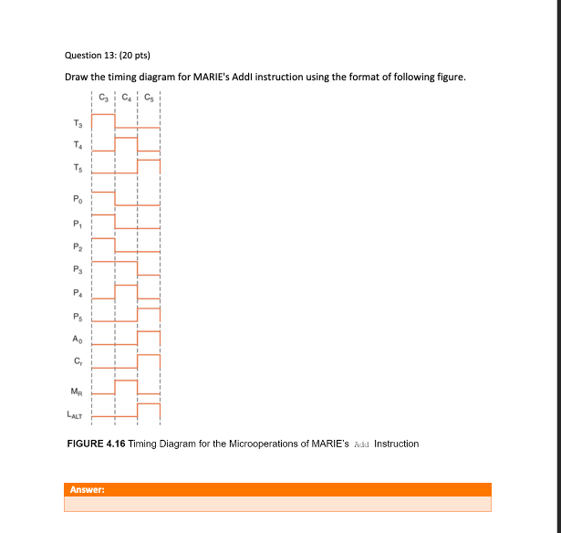
Solved Question 13: (20 pts) Draw the timing diagram for ...
Timing Diagram Basics. Each component you will encounter that communicates over a serial connection, will require understanding the timing of those interactions. Timing diagrams attempt to break these parts up in a way that allows you to understand what needs to be sent or received and in what sequence that needs to happen. Mind you, timing diagrams attempt to do this, sometimes very well, sometimes not so very well.
Timing Diagram Tutorial | Lucidchart
What is the most elegant way to draw a timing diagram specified by a list of zeros and ones? In the following code I attempt to draw the clock pulse diagram, and I'd like to continue drawing the timing diagram for a given input of 0's and 1's, e.g., {11011011,11100110}.

Timing diagram of the inverter shown in Fig. 1b during one ...
This Ultra Quick tutorial shows you how to draw a simple timing diagram and simulate a simple Boolean equation. More comprehensive tutorials are available from the Help > Tutorials menu. 1) Open a new timing diagram file •Choose File > New Timing Diagram menu to open an new timing diagram. 2) Add a clock with a period of 100 ns •Press the ...

How to draw timing diagram from a list of values ...
Developing a Timing Diagram. Click Diagram > New from the toolbar. In the New Diagram window, choose Timing Diagram, then Click Next. You can use the search bar to find the diagram. Name the diagram then click OK. We will name the diagram Select Timing Diagram in this tutorial. You will then see an empty diagram.
![Solved] Given Figure P5.8, draw the timing diagram for Q and ...](https://s3.amazonaws.com/si.question.images/images/question_images/1547/7/2/6/1705c406d5ac29c01547708816416.jpg)
Solved] Given Figure P5.8, draw the timing diagram for Q and ...
Source:EdrawMax Diagram 2: Boat manufacturing process. 4. Conclusion One of the key benefits of a UML timing diagram is that it gives users an overview of what goes on in a system or piece of software. More critically, it shows which steps in a system take too much time, and this information can be used by business users and developers alike to improve their processes.

Timing Diagram for a sequential circuit
The explanation and use of timing diagrams used in digital electronics to graphically show the operation of various circuits are given.Thanks for viewing thi...
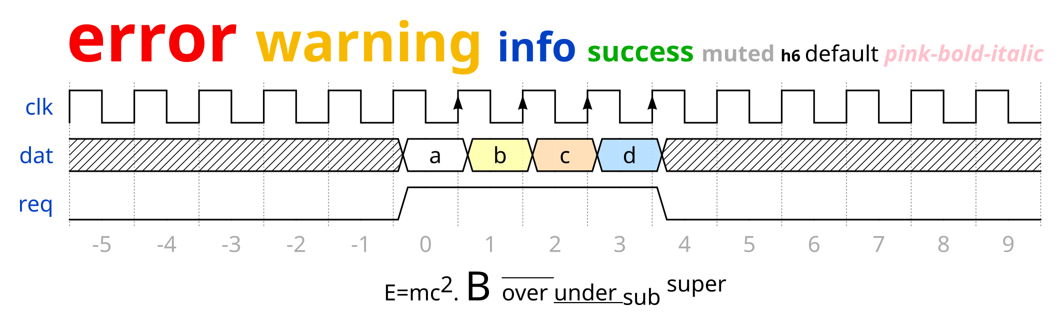
Need Timing Diagrams? Try Wavedrom | Hackaday
To download the diagram, click File > Download As and choose your preferred file type. If you're collaborating on a timing diagram in UML, you have the option to leave comments and see changes in real time with every revision logged for reference so each collaborator sees the most up-to-date version of the diagram.
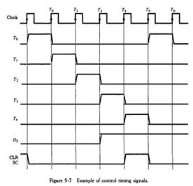
Solved) - Draw a timing diagram similar to Fig. 5-7 assuming ...
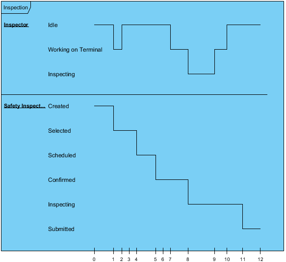
Think of a timing diagram as an inverted sequence diagram. In a timing diagram, time passes on the x-axis from left to right, with different components of the system that interact with each other on the y-axis. Timing diagrams show how long each step of a process takes.

Timing Diagram UML2.0 | Professional UML Drawing
Timing diagram for the positive edge triggered D flip-flop. Clock J X1 K X2 X1 J Q ZZZZ. Timing Diagram of Master Slave D flip flop. J corresponds to a set signal and K corresponds to a reset signal. Draw a timing diagram for this circuit assuming that the propagation delay of the latch is less than the clock pulse width.

Timing diagram with the tikz-timing package | TikZ example
About Parasitic Amp Draw (Battery Drain) in a passenger car. Synchronous Rectifier (SRK1000) in FlyBack reducing voltage with increased current draw: What tool to draw an industrial diagram (PLC's relays, etc) Draw timing diagrams in output of ports P1.0, P1.1, P1.2 for ten cycles? Timing Diagram Draw Tool

Draw Logic Diagram​: Detailed Login Instructions| LoginNote
Timing diagram How To draw UML Timing Diagrams. UML Timing Diagram as special form of a sequence diagram is used to explore the behaviours of objects throughout a given period of time. The difference from sequence diagram is that the axes are reversed so the time is increased from left to right and the lifelines are shown in separate compartments arranged vertically.

how to draw a timing diagram for a logic circuit - Electrical ...
Jan 09, 2015 · Think of the timing diagram as looking at the face of an oscilloscope. There are horizontal lines representing the voltage levels and signals, then there are vertical lines representing time. In this case the best time interval would be 5nS (per each vertical line) since this is the shortest delay time shown and 10nS is divisible by 5nS.

Diagramming Software for Design UML Timing Diagrams | Timing ...
Creating timing diagram. Perform the steps below to create a UML timing diagram in Visual Paradigm. Select Diagram > New from the application toolbar. In the New Diagram window, select Timing Diagram. Click Next. Enter the diagram name and description. The Location field enables you to select a model to store the diagram. Click OK. Creating timing frame
Timing Diagram Basics

What is Timing Diagram?
Homework 5 with Solutions :: Homework :: EECS 31/CSE 31/ICS ...

For each timing diagram, draw a circuit that generates ...

Body
How to design a digital circuit to generate the following ...
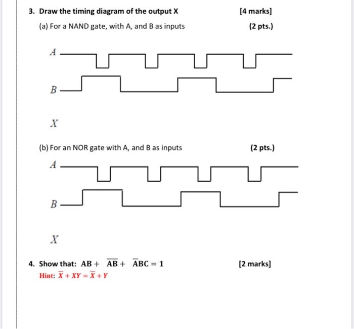
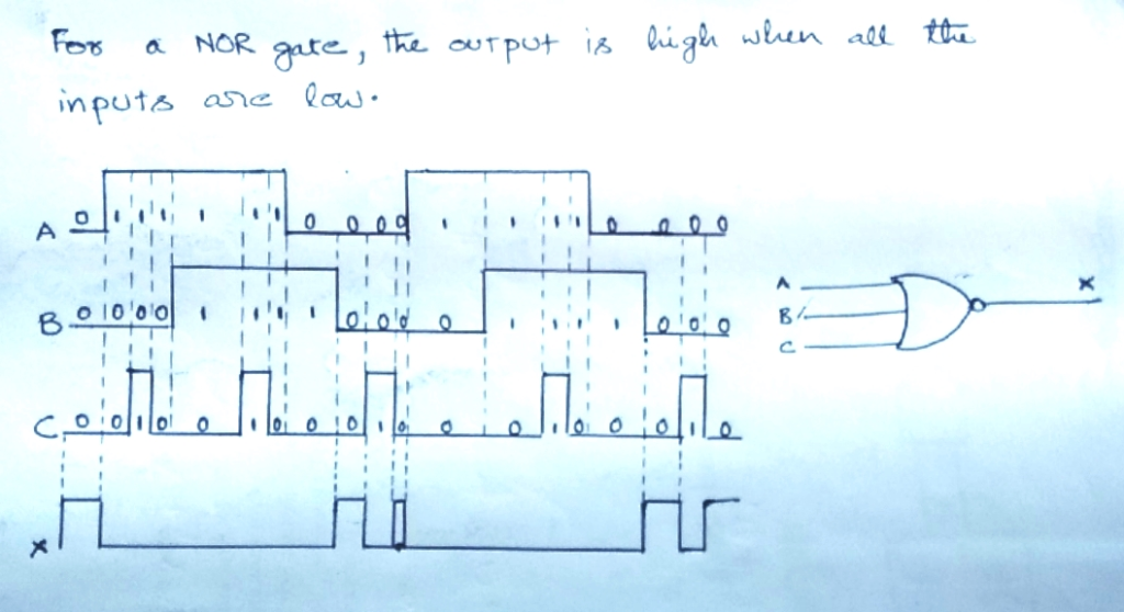
Solved 3. Draw the timing diagram of the output X (a) For a ...
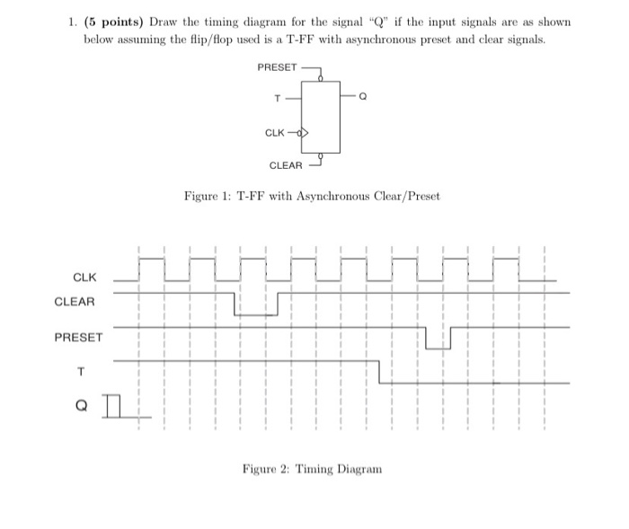
1. (5 points) Draw the timing diagram for the signal | Chegg.com
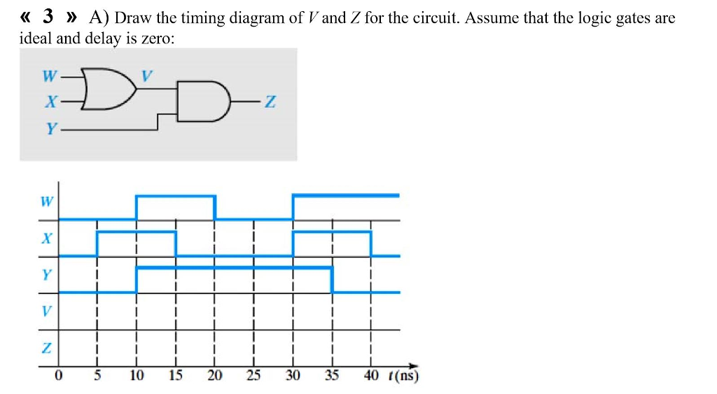
Solved « 3 » A) Draw the timing diagram of V and Z for the ...
Solved: 3 Page 168 Problem 22 22 Determine Output Waveform

b) For the circuit below, draw the timing diagram for outputs ...

For the input shown below, draw the timing diagrams for the ...

Introduction — TimingAnalyzer Documentation
How to Draw a Timing Diagram in UML?

2. Refer to the logic diagram below. Draw the timing diagram ...
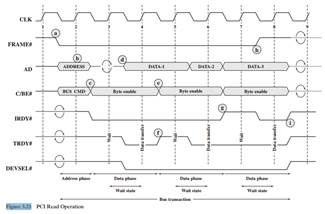
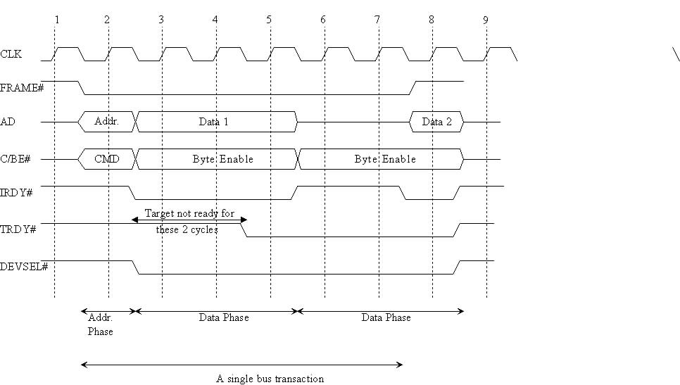
Solved) - Draw and explain a timing diagram for a PCI write ...
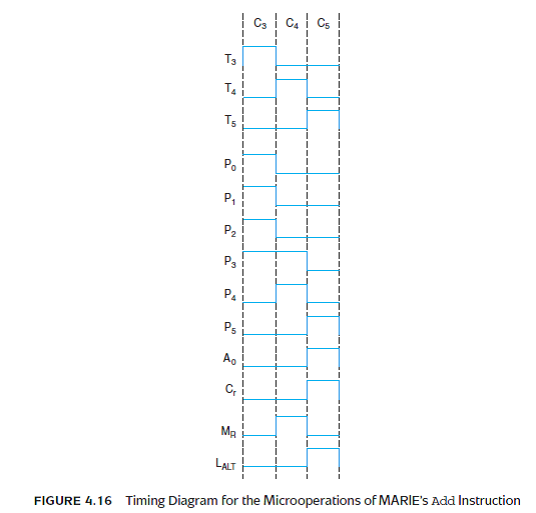
Solved: Draw the timing diagram for MARIE's Load instruction ...
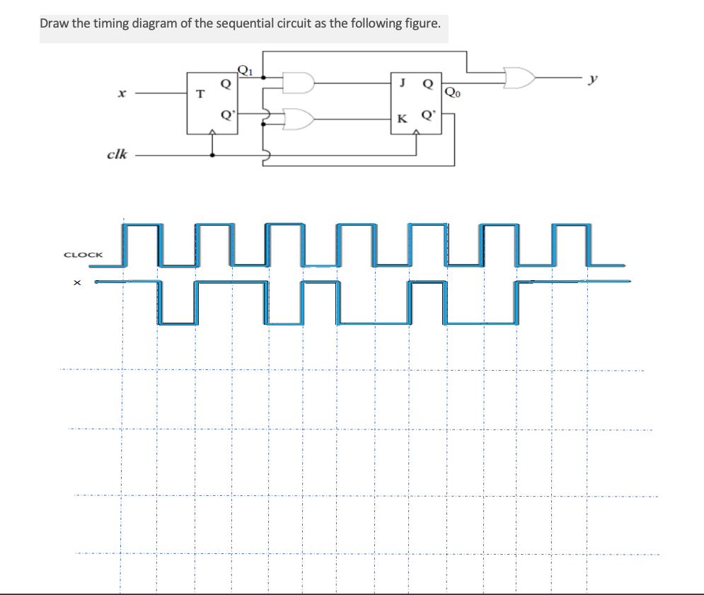
Solved Draw the timing diagram of the sequential circuit as ...
Drawing and Editing Waveforms

CSE370 Assignment 7

How to draw a timing diagram for CSE 120 class - Electrical ...
Body
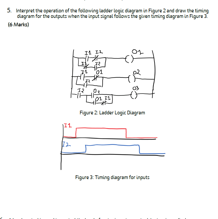
Solved 5. Interpret the operation of the following ladder ...
0 Response to "37 how to draw a timing diagram"
Post a Comment