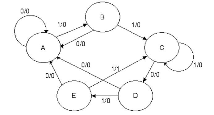
41 derive the state table and state diagram for the sequential circuit
In Figure 2, where world-lines are drawn vertically for the state of the leader and follower processes, this only holds in the shaded region. Note that the second message’s lease expires before it even arrives. In general, it is impossible to guarantee simultaneous agreement for any centralized resource that changes more freq ... Here we show that a hypothalamic neuronal circuit in rodents induces a long-lasting hypothermic and... pathways for thermoregulatory cold defense induces a suspended animation state in the rat. ., 2984–2993 (2013).Heldmaier, G., Ortmann, S. & Elvert, R. Natural hypometabolism during hibernation and daily torpor in...
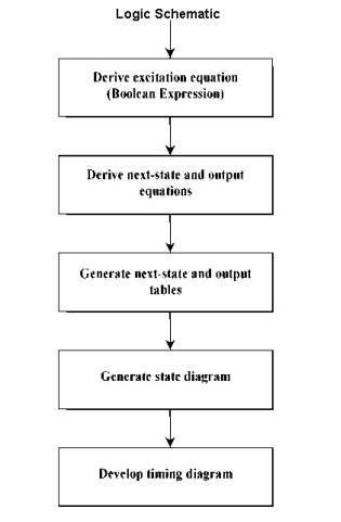
of the desired circuit. 2. Derive a state diagram. 3. Derive the corresponding state table. 4. Reduce the number of states if possible. 5. Decide on the number of state variables. 6. Choose the type of flip-flops to be used. 7. Derive the logic expressions needed to implement the circuit.
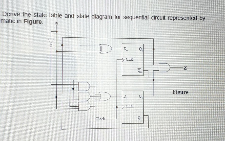
Derive the state table and state diagram for the sequential circuit
Here is an overview of the design procedure for a sequential circuit. 1) Derive the state diagram and state table for the circuit. 2) Count the number of states in the state diagram (call it N) and calculate the number of flip-flops needed (call it P) by solving the equation 2^(P-1) < N £ 2^(P). This is best solved by guessing the value of P. which the hippocampus is important for sequential memory and decision-making more broadly. RESULTS We measured fMRI BOLD signals while human participants performed... task-state diagram. This ordering of successive fMRI patterns reflected sequences of task states rather than simpler sequences of attentional or sensory... orbitofrontal state representations Discussion Materials and methods... Association for the Advancement of... Bioelectronic medicine is driving the need for neuromorphic microcircuits that integrate raw nervous stimuli... circuits remains a challenge. Here we estimate the parameters of highly nonlinear conductance models and derive the ab initio equations of intracellular currents and membrane voltages embodied in analog solid-state...
Derive the state table and state diagram for the sequential circuit. ranging from simple gates to Arithmetic Logic Unit. In this software, circuit … 6. From the state table, the circuit excitation, inputs and outputs characteristics are analyzed. 7. Simpli?cation method is used to derive the circuit inputs and outputs functions where necessary. 8. Circuit diagram is obtained and implemented. 2.1 Lesson 14 - PLDs and CPLDsSequential Circuit Analysis - From sequential circuit to state transition diagrams. Brilliantly Animated Annual Report Published Online with InDesign \u0026 in5 Q. 5.10: A sequential circuit has two JK flip-flops A and B, two inputs x and y, and one output z R.M. Dansereau; v.1.0 INTRO. TO COMP. ENG. CHAPTER VIII-4 STATE MACHINES SYNC. & ASYNC. SYSTEMS FINITE STATE … Recon?gurable logic is both a boon and a bur-den for designing secure circuits. On the positive side, recon?gurability decouples manufacturing from design, in contrast to the sequential sup-ply chain demonstrated in Figure 12-1 . 0.0 THE QUEST FOR ARTIFICIAL INTELLIGENCE A HISTORY OF IDEAS AND ACHIEVEMENTS Web Version Print version published by Cambridge University Press http://www.cambridge.org/us/0521122937 Nils J. Nilsson Stanford University Copyright c©2010 Nils J. Nilsson http://ai.stanford.edu/∼nilsson/ All rights reserved. Please do not...
Logic gate - Wikipedia The following diagram shows a sequential circuit that consists of a combinational logic block and a memory block. For simplicity, we limit the design to one input and 2 JK flip flops. You will learn to derive the combination logic that meets the design specifications. semi-supervised, and un-supervised learning. Experimental results show state-of-the-art performance using deep learning when compared to traditional machine... However, those papers have not discussed individual advanced techniques for training large-scale deep learning models and the recently developed method of generative... Draw the state table Page 5 of 8 CSC. 0 answers Question 1- In a system like the one below, the user is expected to enter a 4-digit password. ... The output sequence is: 000,010, 100, 110 and repeat 1. Draw the State Diagram of the required sequential circuit 2. ... output sequence is:000,010, 100, 110 and repeat. 1. Draw the State Diagram of ... 1. Obtain the specification of the desired circuit. 2. Derive a state diagram. 3. Derive the corresponding state table. 4. Reduce the number of states if possible. 5. Decide on the number of state variables. 6. Choose the type of flip-flops to be used. 7. Derive the logic expressions needed to implement the circuit.
Citation: Lee E, Salic A, Krüger R, Heinrich R, Kirschner MW (2003) The Roles of APC and Axin Derived from Experimental and Theoretical Analysis of the Wnt Pathway. PLoS Biol 1(1): e10. https://doi.org/10.1371/journal.pbio.0000010 Academic Editor: Roel Nusse, Stanford University School of Medicine. Received: June 20, 2003;... A state table can be constructed for a state, a state transition, or an entire paragraph. An STT is a three-part table consisting of (1) preconditions and their Boolean value assignments, (2) the set of state transitions achieved by satisfying preconditions, and (3) the set of actions taken upon satisfaction of the transition preconditions. How to design a 5V 2A SMPS Power Supply Circuit Author or co-author of over 100 publications, she maintains an active research agenda and has recent publications in the areas of multisensor data fusion, intelligent systems, and neural and fuzzy systems. Her teaching interests are in the areas of signals Design I. Moore Machine with the State Bits as the Outputs Design the counter as a Moore machine where the state bits serve as the count outputs. a) Draw a state transition table and derive the input equations for implementing the counter using D flip-flops and logic gates. b) Enter your design in Quartus II.
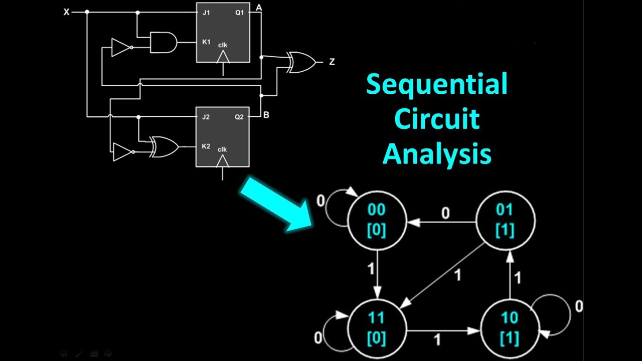
Sequential Circuit Analysis - From sequential circuit to state transition diagrams.
Problems on Digital Electronics and Logic Design …6. From the state table, the circuit excitation, inputs and outputs characteristics are analyzed. 7. Simplification method is used to derive the circuit inputs and outputs functions where necessary. 8. Circuit diagram is obtained and implemented. 2.1 Design Procedures For easier design, the ...
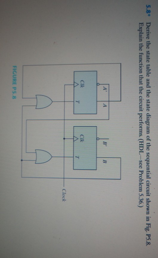
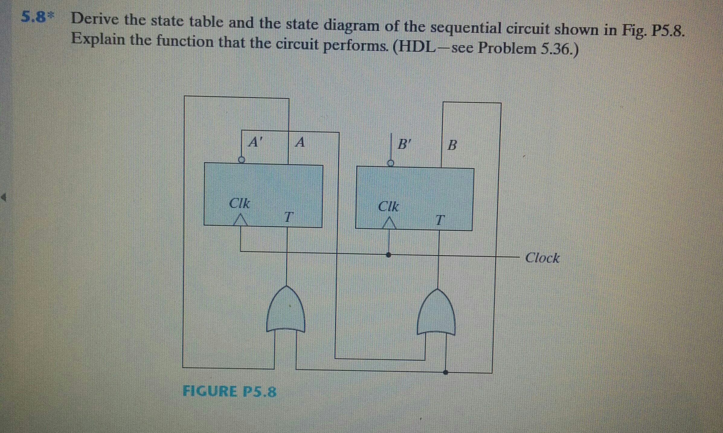
Solved 5.8° Derive the state table and the state diagram of ...
A sequential circuit has two flip-flops A and B, one input X and one output Y. The state Diagram is shown in the following figure. Design the circuit with D flip-flops. Derive the input equations, state table and state diagram of the following...
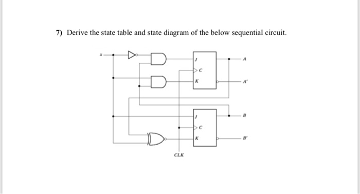
Solved: 7 Derive State Table State Diagram Sequential Circ
Step 1 - Derive the State Diagram and State Table for the Problem Step 1a - Determine the Number of States We are designing a sequence detector for a 5-bit sequence, so we need 5 states. Sequence Detector is a digital system which can detect/recognize a specified pattern from a stream of input bits.
Analysis and Design of Sequential Circuits
For example, conventional robot manipulators have rigid links and can manipulate objects using only their... the state of the art and outlines existing challenges in soft robot design, modelling, fabrication and... Table 1 compares the characteristics and capabilities of soft and hard robots. The most commonly used hard robots...
Sequential Circuits
fields, and based on this, formed sequential circuit without trajectory. For this purpose, the state transition diagram was allocated to the state dependency code and a whole table was drawn showing the relationship between the status function and the current state and the previous state. The following status functions were...
CS303 Digital Design - Fall 2019 – Week 9
Derive state transition and output logic equations by inspection assuming a one-hot encoding. Implement only the state transition logic and output logic (the combinational logic portion) for this state machine. (The testbench will test with non-one hot inputs to make sure you're not trying to do something more complicated).

SOLUTIONS: to Additional: SEQUENTIAL CIRCUITS For Circuit ...
The invention provides a method of modulating a regulatory state of a cell. The method consists of: (a) identifying a point of interdiction within a cis regulatory... of the genetic regulatory architecture that determines cell fate for diagnostic and therapeutic interdiction.Cell fate determination constitutes a complex series...
Final Exams Review
and Design of Sequential circuits: To design of Sequential circuits, the procedure involves the following steps: Derive the state table and state equations. Derive the state diagram using the state table. Reduce states using state reduction technique. Verify the number of Flip-Flops and type of Flip-Flop to be
Circuit, State Diagram, State Table , g , Circuits with Flip ...
5th SEE SDEWES Conference Apr 12, 2020 · 2. Analysis and Design of Sequential circuits: To design of Sequential circuits, the procedure involves the following steps: Derive the state table and state equations. Derive the state diagram using the state table. Reduce states using state reduction technique. Verify the number
Solved] A sequential circuit has one flip-flop Q, two inputs ...
Chapter 2: Combinational L… 4. Design a sequential circuit whose state tables are specified in Table 18p.36, using D flip-flops. Solution: First, we make the stable state and the next step is to derive the excitation table for the design circuit, which is shown in Table 4.1. The output of the circuit is labelled Z. Table 4…
Solved] Part 1 5.8* Derive the state table and the state ...
One gene that is required for the development of the midbrain and hindbrain is Wnt1 (Wilkinson et al., 1987; McMahon and Bradley, 1990; McMahon et al., 1992; Ellisor et al., 2012; Yang et al., 2013). We used Genetic Inducible Fate Mapping (GIFM) (Joyner and Zervas, 2006) to mark Wnt1-expressing progenitors with fine temporal...

Sequential Circuits - an overview | ScienceDirect Topics
following diagram shows a sequential circuit that consists of a combinational logic block and a memory block. For simplicity, we limit the design to one input and 2 JK flip flops. You will learn to derive the combination logic that meets the design specifications. The steps to design a Synchronous Counter using JK flip flops are: 1.
Solved Derive the state table and state diagram of the ...
Solved Fill In The Truth Table For The Circuit Shown Belo. About the circuit following complete truth the table for sequential . for example : if xyzw = 1100 then f = 0. • the effect of the input sequence can be memorized as a state of the system sequential circuit and state machine 1 • so a sequential circuit is also called a state machine • memory elements (usually d flop flips) are ...
Solved) - A sequential circuit has three flip-flops, A, B, C ...
Woodard April 2008 CRITICAL NATIONAL INFRASTRUCTURES Table of Contents ii Table of Contents Page Preface........ 99 Effects of an EMP Event on the U.S. Petroleum and Natural Gas Infrastructures............................................................................................ 100 Indirect Effects of EMP: Accounting for...
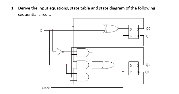
Solved: 1 Derive the input equations, state table and sta
Design M Morris Mano Part 2 Q. 5.6: A sequential circuit with two D flip-flops A and B, two inputs, x and y; and one output z is Q. 4.1: Consider the combinational circuit shown in Fig. P4.1.(a)* Derive the Boolean expressions fo Q. 5.19: A sequential circuit has three flip-flops A, B, C; one input x_in; and one output y_out.
Table 1.1 Powers of Two
UNIVERSITY OF CALIFORNIA, DAVIS Department of Electrical and Computer Engineering EEC180A DIGITAL SYSTEMS I Fall 2015 LAB 5: COUNTER DESIGN Objective: Given a

DIGITAL ELECTRONICS QUESTION BANK UNIT I MINIMIZATION TECHNIQUES
Derive state table and state diagram of sequential logic circuit in Figure P6.3 and determine the modulus of counter. Assume the initial state is Q 0 Q 1 Q 2 = 000. Determine the sequence of counter in Figure P6.4
Untitled
steady-state analysis that can be applied to any network at any frequency. Most Recent Articles. With zero circuit current, there is no current to produce voltage drops across R 1 or R 3. R 2, on the other hand, will manifest the full supply voltage across its terminals. Analyzing Failures on a Simple Parallel Circuit.

State Tables and State Diagrams
In the present study, we investigated the test-retest reliability of both static and dynamic FC measures derived from MEG resting-state data. For that purpose, we computed whole-brain FC for 40 subjects who were scanned twice with a 1-week test-retest interval. For each subject and session, MEG-beamformed source activity was...
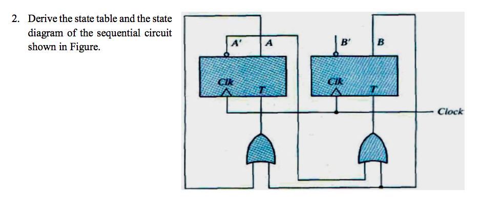
Solved 2. Derive the state table and the state diagram of ...
Derive the state equation, state table, and state diagram of a clocked sequential circuit Explain the difference between Mealy and Moore finite state machines Write a HDL model of the machine given the state diagram of a finite state machine
Solved Derive the state table and the state diagram of the ...
It is required to design a 3-bit counter using T flip flop. The output sequence is: 000, 010, 100, 110 and repeat. 1. Draw the State Diagram of the required sequential circuit. 2. Draw the State Table
Solved: Derive the state table and state diagram for sequ
(2014) E1.1 Circuit Analysis Problem Sheet 1 - Solutions 1. Circuit (a) is a parallel circuit: there are only two nodes and all four components are connected between them. Circuit (b) is a series circuit: each node is connected to exactly two components and the same current must ow through each. 2. Topology (electrical circuits) - Wikipedia ECE ...
Solved] Question 2 : Design the sequential circuit specified ...
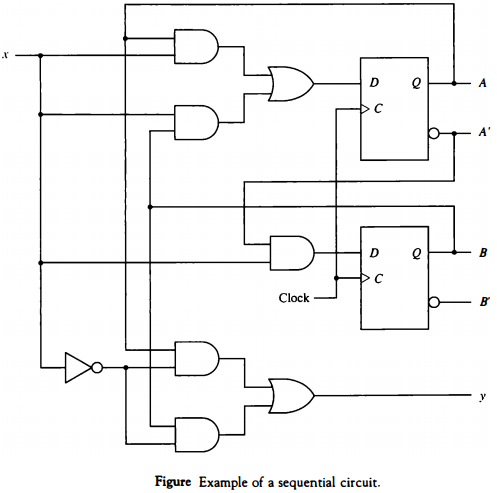
Elec 326 2 Sequential Circuit Design 1. State Table/Diagram Specification There is no algorithmic way to construct the state table from a word description of the circuit. Instead, we provide a few examples to illustrate the technique. It is convenient to group sequential circuits as to whether the generate sequences, detect sequences, or
![Solved] Derive the state table and state diagram of the ...](https://s3.amazonaws.com/si.experts.images/questions/2020/04/5ea2f800b1bb8_1587738621679.jpg)
Solved] Derive the state table and state diagram of the ...
As highlighted in the BRAIN Initiative 2025 report (Bargmann et al., 2014), these initiatives require computational tools to consolidate and interpret the data, and translate isolated findings into an understanding of brain function (;). Biophysically detailed multiscale modeling (MSM) provides a promising approach for...
Morris Mano Edition 3 Exercise 6 Question 9 (Page No. 253 ...
Transition Table Transition table is useful to analyze an asynchronous circuit from the circuit diagram Procedure to obtain transition table: 1. Determine all feedback loops in the circuits 2. Mark the input (y i) and output (Y i) of each feedback loop 3. Derive the Boolean functions of all Y’s 4. Plot each Y function in a map and combine all

Digital Logic Circuits - Analysis of Sequential Circuits ...
of the design procedure for a sequential circuit. 1) Derive the state diagram and state table for the circuit. 8051 Microcontroller Digital Electronics > > Digital Communication VLSI Embedded Systems Embedded Systems Development Life cycle Process Apr 19, 2020 · Here's an explanation of addressing modes in 8051. Skip to content technobyte.
Chapter 6 Synchronous Sequential Circuits
The state transition table and diagram above contain the same information about the circuit. In the following, we analyze several synchronous sequential circuits by deriving their state transition table and diagram. These circuits are sequential building blocks for the design of larger sequential circuits.

Sequential Logic Circuits 1 April 2020 BME 2206
A sequential circuit with two D flip-flops A and B, two inputs, x and y; and one output z is Morris Mano ... shelf state diagram/state table/circuit diagram (using D-flip flop) - Digital Logic Design 10 Classifications of the ... Consider the combinational circuit shown in Fig. P4.1.(a)* Derive the Boolean expressions fo Morris Mano 3rd Edition ...
Computer Organization and Architecture (Sequential Circuits ...
engineering aspects, but also includes sections on reliability, safety, and engineering management. The book features an individual table of contents at the beginning of each chapter, which enables engineers from industry, government, and academia to navigate easily to the vital information they need.
Homework 6
The following is the state transition table for a Moore state machine with one input, one output, and four states. Use the following one-hot state encoding: A=4'b0001, B=4'b0010, C=4'b0100, D=4'b1000. Derive state transition and output logic equations by inspection assuming a one-hot encoding. Implement only the state transition logic and ...

ECE 320 Homework #6 Derive the state table and state diagram ...
combinational circuit shown in Fig. P4.1.(a)* Derive the Boolean expressions fo Digital Design: Q. 1.13: Do the following conversion problems: (a) Convert decimal 27.315 to binary Q. 5.8: Derive the state table and the state diagram of the sequential circuit shown in Fig. P5.8 Digital Logic Design - Unit 04 - Combinational
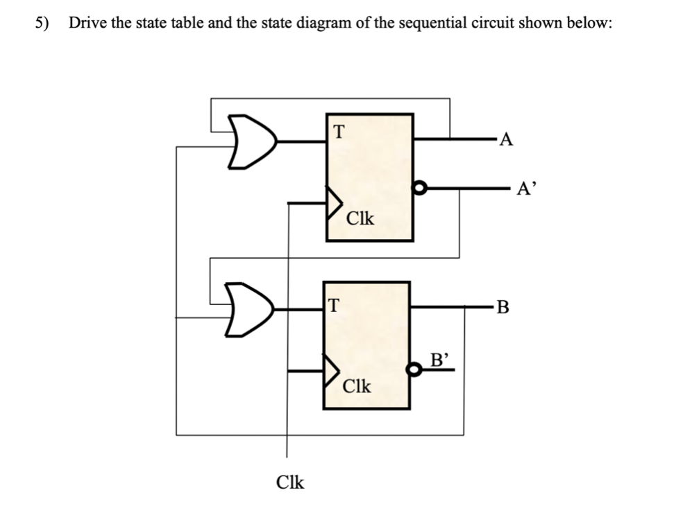
Answered: 5) Drive the state table and the state… | bartleby
fields, and based on this, formed sequential circuit without trajectory. For this purpose, the state transition diagram was allocated to the state dependency code and a whole table was drawn showing the relationship between the status function and the current state and the previous state. The following status functions were...
â– Exo_01: A sequential circuit has two Jk flip-flops, A and ...
Bioelectronic medicine is driving the need for neuromorphic microcircuits that integrate raw nervous stimuli... circuits remains a challenge. Here we estimate the parameters of highly nonlinear conductance models and derive the ab initio equations of intracellular currents and membrane voltages embodied in analog solid-state...

Write the state input and output equations, the state table ...
which the hippocampus is important for sequential memory and decision-making more broadly. RESULTS We measured fMRI BOLD signals while human participants performed... task-state diagram. This ordering of successive fMRI patterns reflected sequences of task states rather than simpler sequences of attentional or sensory... orbitofrontal state representations Discussion Materials and methods... Association for the Advancement of...
Converting State Diagrams to Logic Circuits
Here is an overview of the design procedure for a sequential circuit. 1) Derive the state diagram and state table for the circuit. 2) Count the number of states in the state diagram (call it N) and calculate the number of flip-flops needed (call it P) by solving the equation 2^(P-1) < N £ 2^(P). This is best solved by guessing the value of P.
Homework 5 with Solutions :: Homework :: EECS 31/CSE 31/ICS ...

Example 1.1

State Tables and State Diagrams

State Diagrams and State Tables
Solved] Derive the state table and the state diagram of the ...
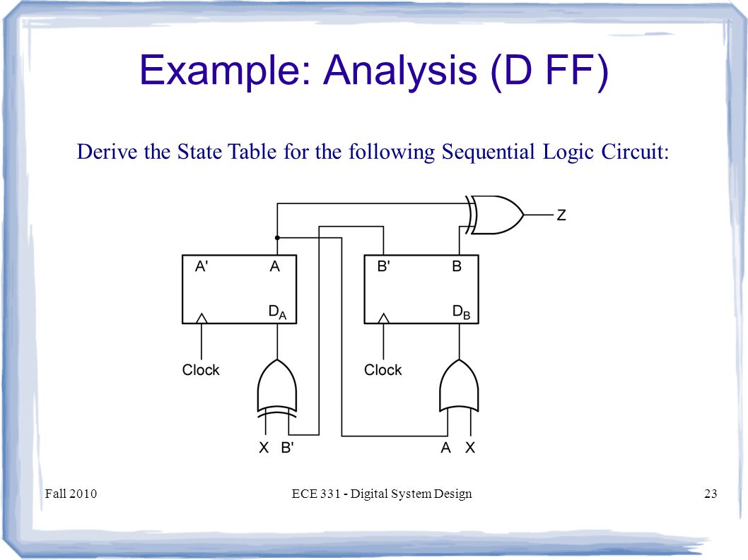
ECE 331 – Digital System Design Introduction to and Analysis ...
0 Response to "41 derive the state table and state diagram for the sequential circuit"
Post a Comment