38 fuel oil tank installation diagram
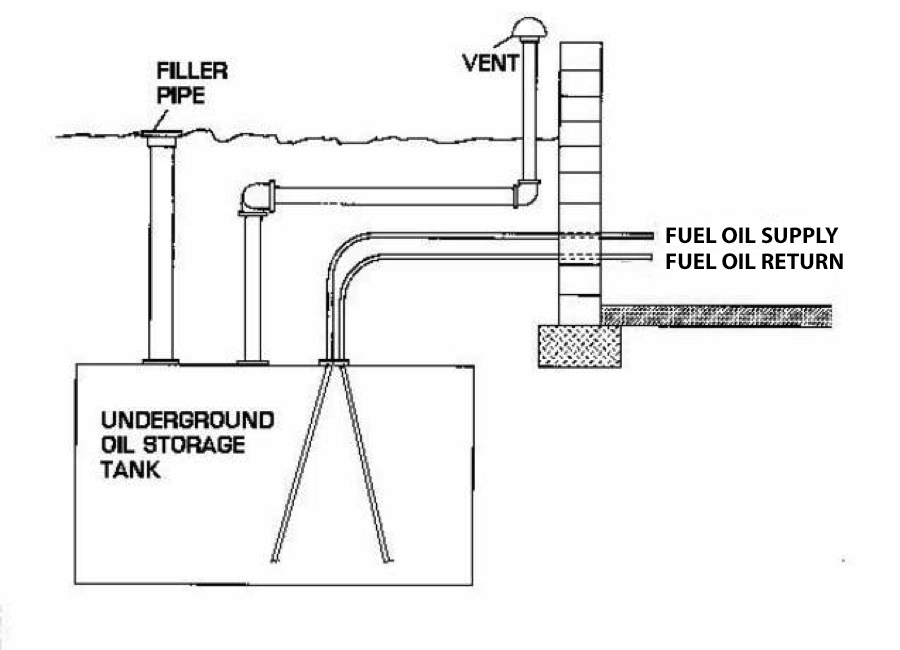
PDF Aboveground Storage Tank (AST) New Installation/First Fill ... Date of Tank Install: _____ The number at the end of each question refers to the tank diagram on page 2 of this checklist . Is the tank on a stable concrete pad/foundation at least 4 inches thick and footprint exceeding dimensions of tank by at least 10%? (1) ☐ Yes How to Hook Up a 2-Line Oil Furnace | eHow The supply line delivers fuel oil from the holding tank to the fuel pump. The return line sends excess oil not used by the furnace back to the oil tank. The two-line system is most commonly used in underground oil tanks or tanks located lower than the furnace's oil burner. You can hook up a two-line system with a few tools and basic mechanical ...
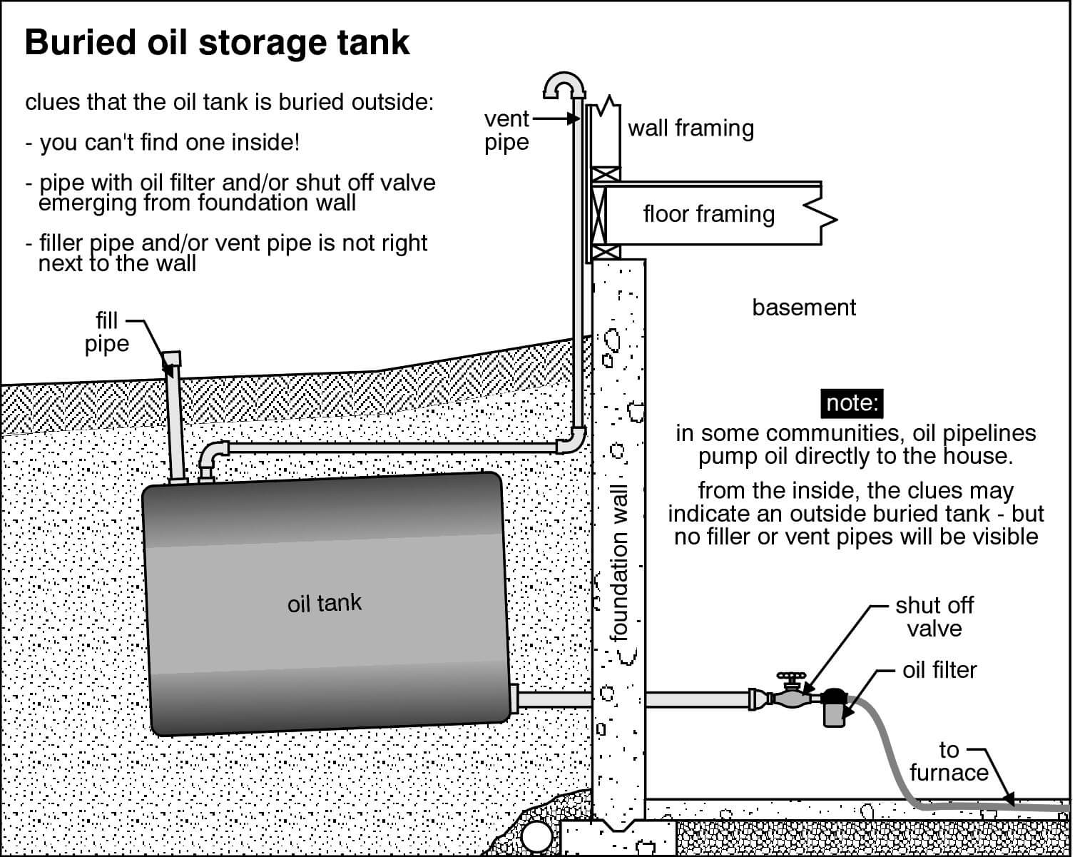
Fuel Oil Tank Installation Diagram - HeatFleet Installing an oil tank can be an involved process. However, taking the measures described below and shown in the diagrams will help you in your journey in fuel oil tank installation. Step 1. First, find a place for your new oil tank to be installed.
Fuel oil tank installation diagram
PDF NFPA 31 Fuel Oil Piping, Installation and Testing Chapter ... This chapter shall apply to piping systems and their components used to transfer fuel oil from storage and supply tanks to oil-burning appliances and equipment. 8.2 Acceptable Piping Materials and Piping System Design. 8.2.1 Tank fill and vent piping shall be wrought-iron, steel, or Schedule 40 brass pipe. Oil supply lines shall be steel pipe or brass or copper tubing. Wall thickness of wrought- fuel-oil-tank-installation-diagram - blog.heatfleet.com Installing an oil tank can be an involved process. However, taking the measures described below and shown in the diagrams will help you in your journey in fuel oil tank installation. Step 1. First, find a place for your new oil tank to be installed. Fuel Oil System Diagram on Ship with Diagram Marine Diesel ... The diagram below shows a Fuel oil supply system for a large 2 stroke crosshead engine In the system shown in Figure, the oil from the service tank flows through a three-way valve to the supply pump. After that it goes to the mixing column through a filter and flow meter. A flow meter is fitted into the system to indicate fuel consumption.
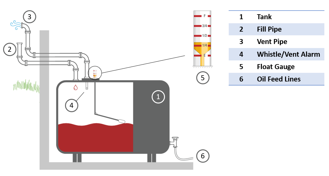
Fuel oil tank installation diagram. PDF NFPA 30 Aboveground Tank Installation - CIMICO 4.3.1.4 Where a tank is located in an area subject to flooding, provisions shall be taken to prevent tanks, either full or empty, from floating during a rise in water level up to the maximum flood stage . 4.3.2 Installation of Aboveground Tanks . 4.3.2.1 Location with Respect to Property Lines, Public Ways, and Important Buildings on the Same ... PDF FUEL OIL PIPING AND STORAGE - Home | ICC Store FUEL OIL SYSTEM INSTALLATION 1305.1 Size. The fuel oil system shall be sized for the maxi-mum capacity of fuel oil required. The minimum size of a supply line shall be 3/ 8-inch (9.5 mm) inside diameter nominal pipe or 3/ 8-inch (9.5 mm) od tubing. The minimum size of a return line shall be 1/ 4-inch (6.4 mm) inside diameter nominal pipe or 5/ 16 Fuel Oil System for Marine Diesel Engine A diesel oil daily service tank may be installed and is connected to the system via a three-way valve. The engine can be started up and manoeuvred on diesel oil or even a blend of diesel and heavy fuel oil. The mixing tank is used to collect recirculated oil and also acts as a buffer or reserve tank as it will supply fuel when the daily service ... Guidelines for Installing Above Ground Oil Tanks Joints in the piping should be made fuel oil tight by using joint compound. Vent pipe must measure 2in nominal. Installing Above Ground Oil Tanks Details: All tanks must be connected to a vent alarm which is a way to prevent spills. The fill pipe must measure 3ft above the grade. The vent pipe measures 6in above the grade.
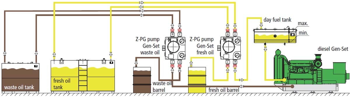
PDF Domestic Oil Tank Bases Construction and Design Table 1 - Approximate weight of tank. require that fire protection to the stored fuel is provided via the base (a base is defined as the part of the construction in contact with the ground) on (in the case of ground level installations) or above (in the case of raised installations) which the oil tank is installed. PDF Fuel oil treatment - Alfa Laval High-viscosity fuel oils require heating before water washing and, critically, before centrifugal separation. Two stages of washing and separation are often necessary. Heavy fuel oil forwarding The major functions of a heavy fuel for-warding system are: pumping, heating, fuel selection, filtration, and metering Heating requirements will vary depend- Chapter 13: Fuel Oil Piping and Storage, Mechanical Code ... 1301.4 Fuel Tanks, Piping and Valves. The tank, piping and valves for appliances burning oil shall be installed in accordance with the requirements of this chapter. Where an oil burner is served by a tank, any part of which is above the level of the burner inlet connection and where the fuel supply line is taken from the top of the tank, an ... PDF 9.5.4 Diesel Generator Fuel Oil Storage and Transfer System The fuel oil unloading station en ables the transfer of fuel oil from a bulk fuel oil carrier to the storage tank. There are two unloading stations for each fuel oil storage tank. The unloading stations are separated by di stance and out of line of sight. The unloading stations are located above the flood level. The fill and pump-out lines are
The nine major steps of designing generator fuel systems For example, if the usable capacity requirement is 4,000 gal, a 5,000-gal fuel tank should be considered. For applications requiring a high level of resiliency, consider multiple fuel tanks so that isolated tank issues (e.g., contaminated fuel or component failure) do not jeopardize genset operation. Fuel oil storage PDF Installation Manual and Operating Guidelines 1.2.4. Use the Tank Installation Checklist (back of manual) for all single-wall tanks (SW), double-wall tanks (DW), oil/water separators (OWS) and multicompartment tanks (MC) as the in-stallation proceeds. 1.2.5. Relevant information for each tank installed must be recorded on the Tank Installation Checklist found at the back of this manual. How to Install a Heating Oil Tank | eHow Install the oil filter and shutoff valve to the supply line at the front base of the oil tank. Connect the shutoff valve to the supply line at the base of the tank. If a problem ever arises, this valve can prevent oil from flowing. Connect the oil filter to the shutoff valve. Diesel Fuels & Diesel Fuel Systems Foreword This section of the Application and Installation Guide generally describes Diesel Fuels and Diesel Fuel Systems for Cat® engines listed on the cover of
Oil Tank Removal Services | Underground Vs. Above Ground
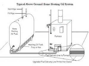
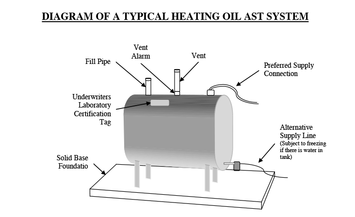
PDF Diagram of A Typical Heating Oil Ast System with National Fire Protection Association Code Standard 31 entitled "Installation of Oil-Burning Equipment" and perform routine maintenance on both old and new tank systems. The following checklist can aid you in proper maintenance of your heating oil aboveground storage tank system (AST). DIAGRAM OF A TYPICAL HEATING OIL AST SYSTEM

Oil Tanks & Other Tanks, Inspection Report Language Example ...
PDF Fuel Oil System - Uniri aIn the system shown in the diagram above the oil is stored 1 through a three-way valve to a mixing tank. bAfter passing through centrifuges 2 to indicate fuel consumption. cFrom the daily service tank the oil flows 3 in tanks in the double bottom from which it is pumped to a settling tank and heated.
Fuel Oil Tanks | Combined Energy Services
Dual oil tanks - Fine Homebuilding First, turn off the valve on the 3/8-in. copper supply line at the base of the existing tank, and disconnect that line. Then take a new 3/8-in. copper line, and sweat a copper T into it. If the supply is made of soft, flexible copper, all the connections including the T should be made with flare fittings.

Mitchell - Heating oil storage tanks are considered to be one ...
fuel diagram for 250 bravo - Snowmobile Fanatics It's the line that goes around the gas tank and both lines off the oil recovery but not the intake from the oil tank that's fine. Can someone please give me a detailed explanation or pics showing the entire line.
Oil Tank Removal Frequently Asked Questions
Oil Tank Installation Guidelines | Quick Environmental Tanks shall be installed on the lowest floor of the dwelling. Inside tank (s) shall be located not less than 5 feet (1.5 m) from any fuel-fired equipment. The tank shall be placed in an area where it is unlikely to be adversely affected by normal household activities.
Heating Oil Tanks - Lake Washington Building Inspection ...
PDF Fuel Oil Piping System Part 1 - General D. Tank Probes: Provide probes suitable for installation in tank(s) via a 4" riser pipe. Probes shall be temperature compensated to correct for fuel oil temperature variations. E. Leak Detection Mode: The monitoring system shall be capable of detecting leakage rates as small as 0.2ÿgallons per hour.
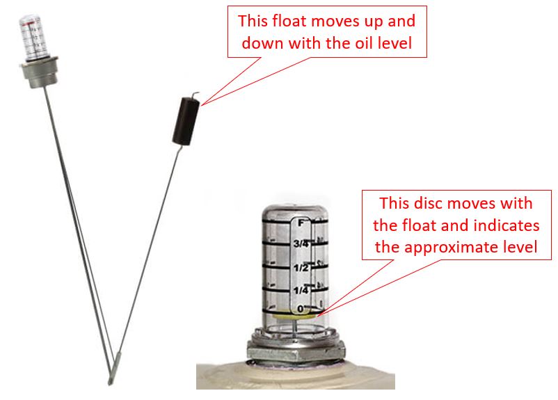
How To Replace Your Heating Oil Tank Gauge | FuelSnap
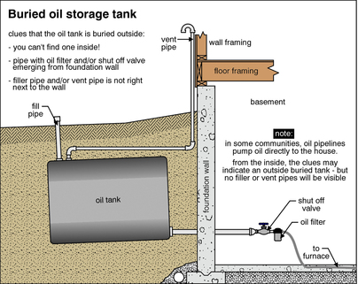
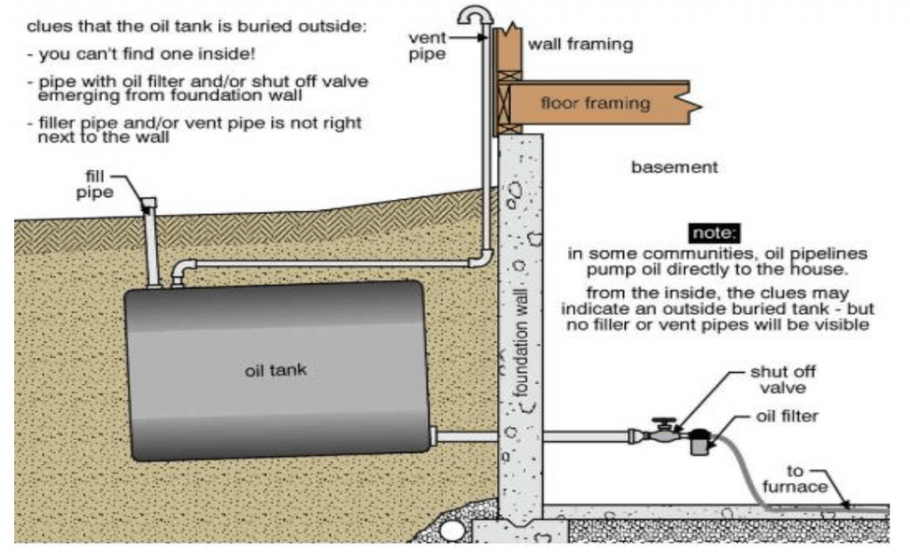
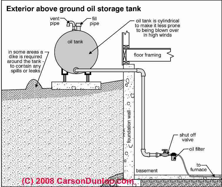
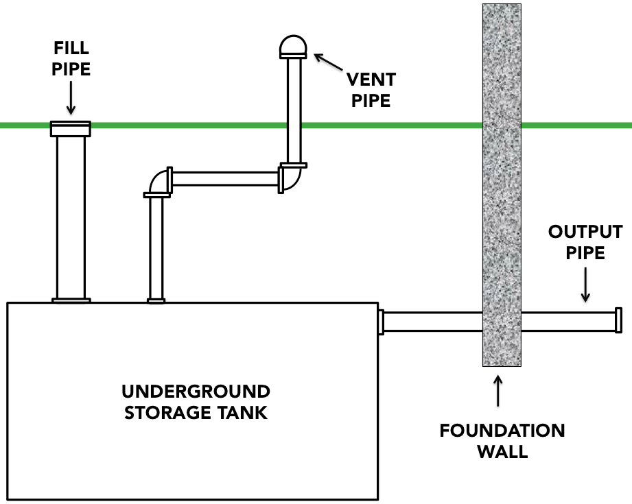
PDF READY Oil Tanks and Piping Chapter require you to install a tank that is either larger or smaller, but in general, it is best to apply the 1/3 rule when possible. Location There are three possible locations for a tank installation: 1. Inside a building—usually in the basement, utility room or garage 2. Outside, above-ground 3. Outside, underground Before selecting a tank location, be sure
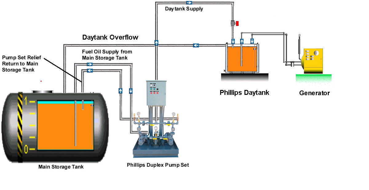
Phillips Pump: Guide Specification for Generator Daytank ...
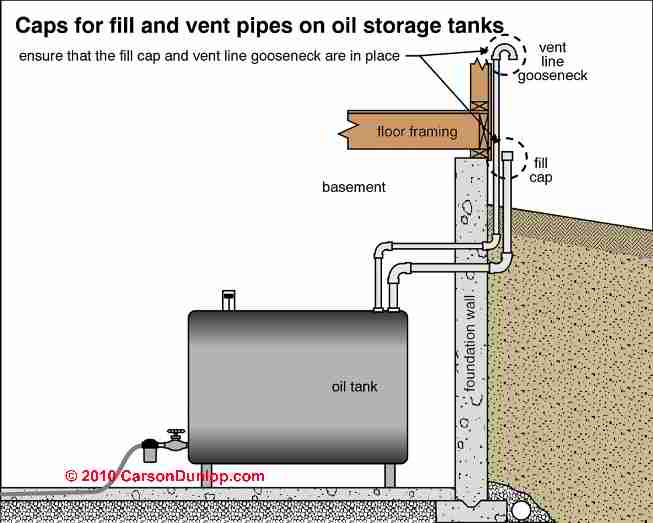
Oil Tank Fill & Vent Piping Installation & Inspection In the photo a 1 1/2" vent line is installed. The oil company recommends going to 2", and most new installations use a two-inch diameter vent pipe; we've seen vent piping as small as one inch on oil tanks. During fill fuel is delivered at an average rate of 60 or even 70 gallons per minute.

Schematic diagram of the purified and distillation system ...
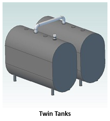
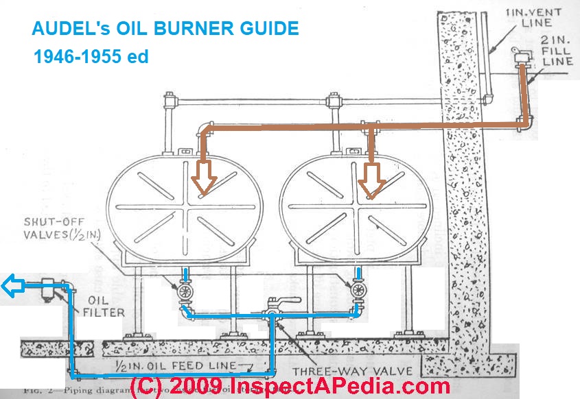
Oil Piping for Duplex or Paired Oil Storage Tanks That installation, unlike the older Audel sketch, complies with more-current dual oil tank installation piping suggested in NFPA 31 (2020) cited below. The oil tank filler pipe is connected to the first oil tank (the rear tank of the pair in our photo) at an oil tank top inlet fitting accepting a 2" diameter filler pipe.
Duplex or Paired Oil Storage Tank Piping FAQs
oil tank piping - DoItYourself.com Community Forums oil tank piping. I have installed a Roth double walled tank with the Roth suction assembly. I have it set up as a one line system. The suction assembly comes with a built-in check valve and thermal fuse valve. In the beckett burner installation guide it says not to use a check valve in a one pipe gravity feed system.

Guidelines for Installing Above Ground Oil Tanks
Chapter 13: Fuel-Oil Piping and Storage, NYC Mechanical ... Fuel-oil storage tanks installed above ground on the lowest floor of a building shall be mounted on and anchored by adequate noncombustible supports. The maximum size of each individual tank shall be 660 gallons (2500 L), and a total of not more than 1375 gallons (5200 L) shall be stored within the same 2-hour fire area.
How an Oil Tank Works - Smart Oil Gauge
Fuel Oil System Diagram on Ship with Diagram Marine Diesel ... The diagram below shows a Fuel oil supply system for a large 2 stroke crosshead engine In the system shown in Figure, the oil from the service tank flows through a three-way valve to the supply pump. After that it goes to the mixing column through a filter and flow meter. A flow meter is fitted into the system to indicate fuel consumption.
READY Oil Tanks and Piping Chapter.p65
fuel-oil-tank-installation-diagram - blog.heatfleet.com Installing an oil tank can be an involved process. However, taking the measures described below and shown in the diagrams will help you in your journey in fuel oil tank installation. Step 1. First, find a place for your new oil tank to be installed.

Above ground oil tank requirements have been updated for ...
PDF NFPA 31 Fuel Oil Piping, Installation and Testing Chapter ... This chapter shall apply to piping systems and their components used to transfer fuel oil from storage and supply tanks to oil-burning appliances and equipment. 8.2 Acceptable Piping Materials and Piping System Design. 8.2.1 Tank fill and vent piping shall be wrought-iron, steel, or Schedule 40 brass pipe. Oil supply lines shall be steel pipe or brass or copper tubing. Wall thickness of wrought-
Vacorda Fuel Oil Tank Meter Gauge Ultrasonic Water Level 4 ...
Diesel Petrol Gasoline Storage Tank Oil Vessel for Fuel Station ...
7 About Oil Tanks by Oil Tank Services ideas | oil storage ...

PDF) Research on Application of Trap Valve in Oil Tank Heating

FUEL TANK ASSEMBLY (6 GALLON) - Various Years Rigging Fuel ...

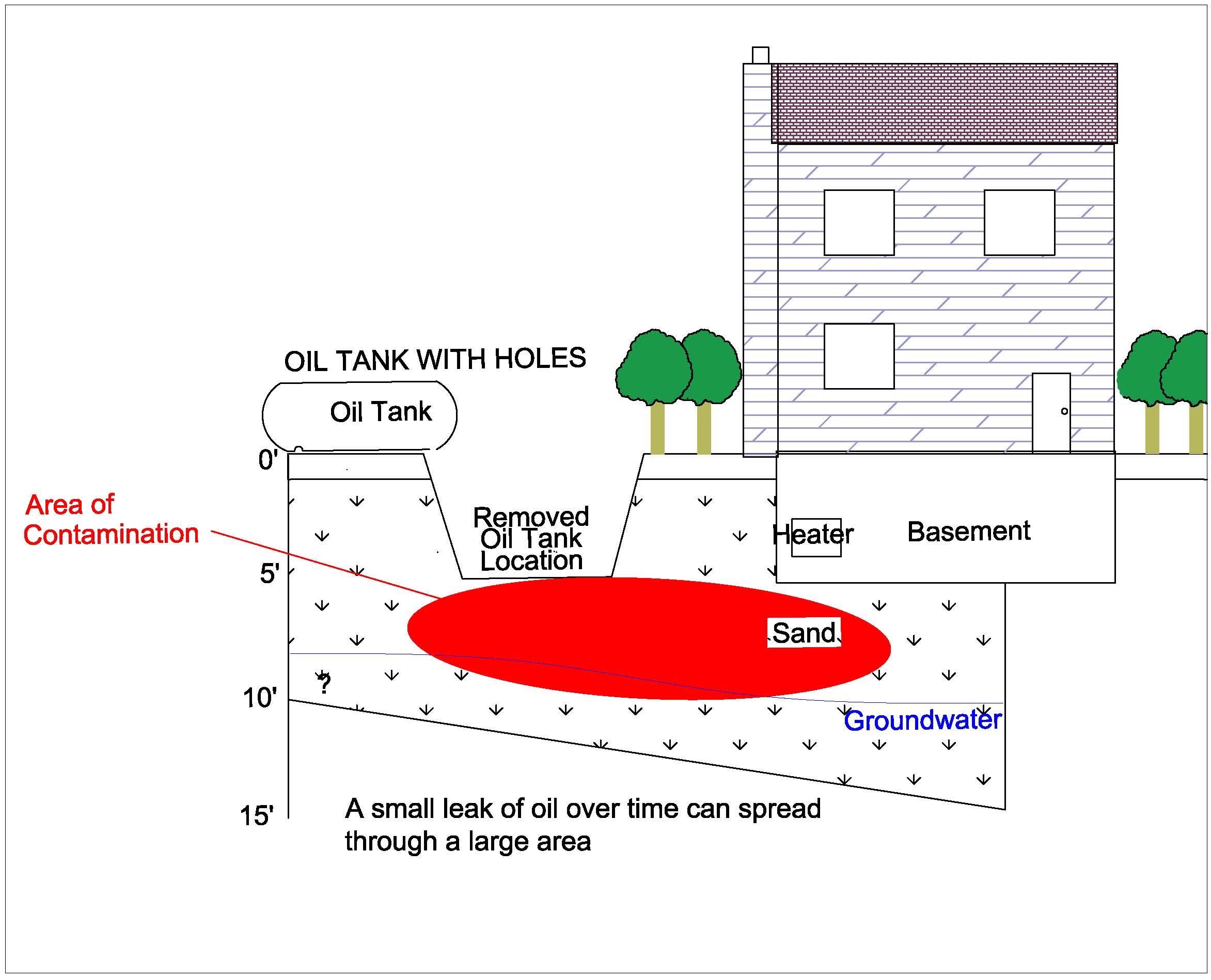
Investigating Fuel Oil Leaks and Spills – Expert Article ...

Fire pump National Fire Protection Association Diesel fuel ...
Self Help & FAQs - Husky Heating Oil
Ölversorgungsanlagen für Kraftwerke, Bergbaumaschinen ...

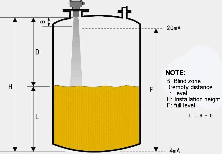
Level sensor for controlling filling level of fuels and oils
pdf.jpg?width=500&height=458&name=500%20gallon%20heating%20oil%20tank)pdf.jpg)
How do you remediate a leaking oil tank, aka oil tank cleanup
How an Oil Tank Works - Smart Oil Gauge

Oil Tanks and Piping
Mercury Rigging Parts & Accessories Fuel/Oil Tanks, Fuel ...
Get to Know Your Oil Storage Tank
What About Fuel Oil Tanks?
Above Ground Outdoor Heating Oil Storage Tanks (ASTs ...

Fuel Tank Replacement in Southern CT | Sippin Energy
SUPERVISE FUEL-OIL PIPING AND STORAGE IN BUILDINGS
The Homeowner's Guide to Underground Oil Tank Removal ...
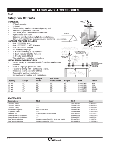
OIL TANKS AND ACCESSORIES Safety Fuel Oil Tanks Roth | Manualzz
Flexible Piping Systems for Fuel Oil and Generator ...
Oil Piping for Duplex or Paired Oil Storage Tanks
Home Heat Tank Systems Technical Standards Handbook
0 Response to "38 fuel oil tank installation diagram"
Post a Comment