40 pod brake controller wiring diagram
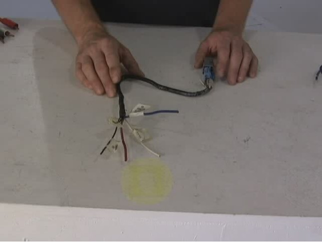
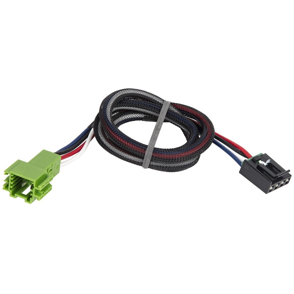
Seni Budayaku - grinditcoffee.pl On coding you can probably copy everything and only enable new Feature, or depending on your prior BCM you need to compleetely code the BCM new and change the Wiring. 0 engine diagram, 2001 vw jetta engine diagram, 2001 vw jetta tdi engine diagram, 2001 vw jetta vr6 engine diagram Edit May 12, 2020 · 2013 Vw Jetta Wiring Diagram – wiring diagram is a … Troubleshooting Reese Pod Brake Controller Indicator Light ... The Reese Pod brake controller should be connected as follows. White - Ground Black - 12 Volt Constant Power Red - Cold Side of the Brake Pedal Switch Blue - Trailer Brake feed to Trailer Brakes If you are correctly wired and you are still experiencing problems, I would start with the following test. Start by disconnecting the blue brake feed ...
reese trailer brake controller wiring - More Trails, More ... Reese Pod Brake Controller Wiring Diagram tip wiringall.com. Buy Now: Wiring Kit for 2 to 4 Brake Control Systems, Includes 25 ft. Duplex Wire, 20 Amp Circuit Breaker and Attaching Terminals. $ Wiring Kit for 6 to 8 Brake Control. Brake Controllers.

Pod brake controller wiring diagram
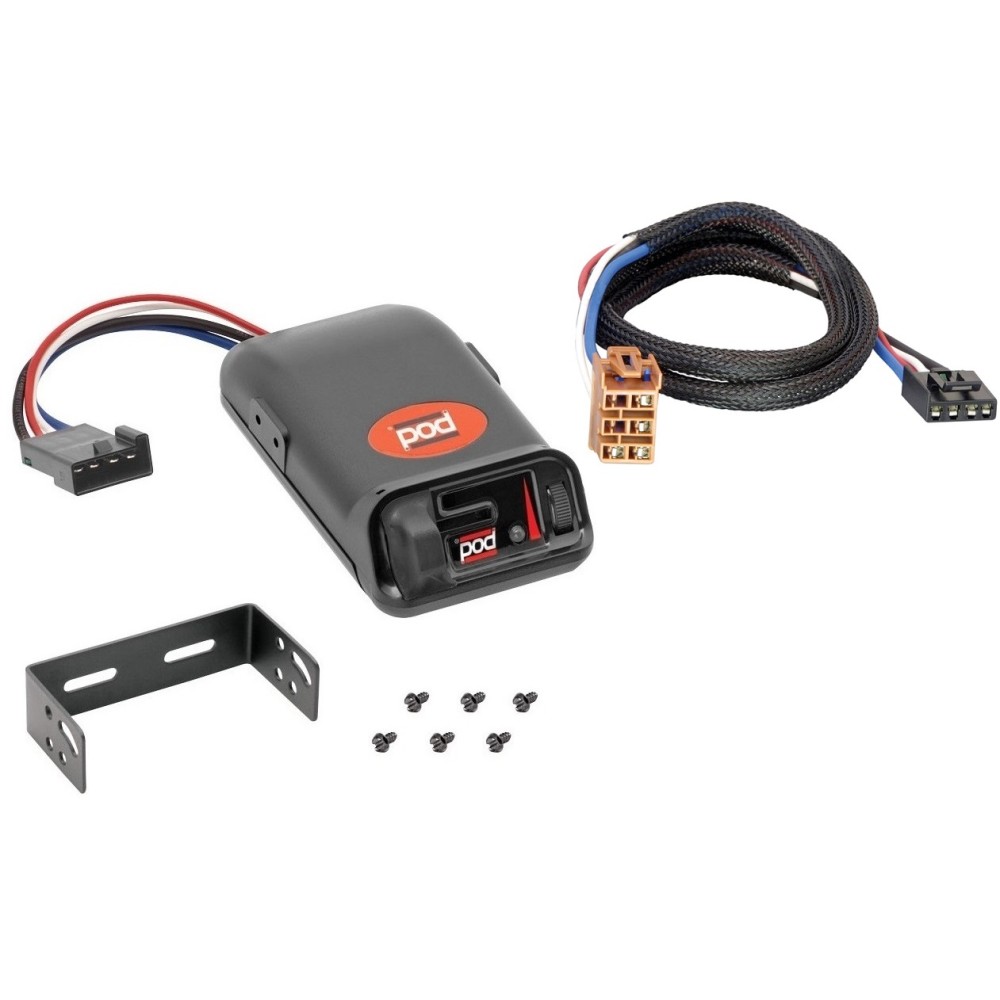
Tekonsha Pro Series POD® Trailer Brake Controller, Timed ... To see our price, add these items to your cart. Add all three to Cart. Choose items to buy together. This item: Tekonsha Pro Series POD Trailer Brake Controller, Timed, 1 to 2 Axles. $36.30. In Stock. Ships from and sold by Amazon.com. FREE Shipping. Tekonsha 3035-P Brake Control Wiring Adapter for Ford. SOLVED: Battery drain overnight 2003 chevy silverado - Fixya 2015-03-05 · Disconnect the auxiliary power cable from the under-hood distribution center that runs to the anti-lock brake controller. Remove the ignition relay from this distribution center (this will isolate/eliminate/indicate the problem as the ignition switch). Unplug any GPS add-on device, and any radar detector, stereo amplifier add-on, I-pod, trailer brake controller add-on, … Reese Pod Brake Controller Wiring Diagram 1. Connect the supplied pigtail wiring harness into the electrical connection port on the rear of the pod brake controller. Purchase a wiring harness specific to your vehicle application from your vehicle's manufacturer, and plug that harness into the recommended connection portal. Reese has always strived to provide the right trailer towing ...
Pod brake controller wiring diagram. Installing Hayman Reese Brake Controllers and Wiring ... Presented by Hayman Reese technical towing expert Gary Gardiner, watch the typical installation process of Hayman Reese Brake Controllers, including end-to-e... Reese Pod Brake Controller Wiring Diagram - schematron.org Reese Pod Brake Controller Wiring Diagram 16.08.2018 16.08.2018 6 Comments on Reese Pod Brake Controller Wiring Diagram schematron.org Today on this Chevrolet Silverado were going to install part number The Pod (Power on Demand) trailer brake control is your best choice, Accu- Power Pod Brake Controller, Tekonsha Installation Instructions ... sistemabatesarchivio.it 1 day ago · Michigan's only urban public research university. With more than 400 degree programs and a location in the heart of Detroit's cultural center, Wayne State offers a distinctive educational experience to students from around the world. dink-magazin.de 2022-03-05 · A check engine light due to low oil pressure is a common complaint in GM (General Motors) vehicles years 2007-2016 that have V8 engines. pl The brake controller wires for a brake controller like the Tekonsha Prodigy P2 Trailer Brake Controller part # 90885 on your 2019 GMC Canyon should be located under the driver side kick panel next to the emergency …
Reese Pod Brake Controller Wiring Diagram - easywiring Place the pod controller inside the cab of the vehicle near its. Hayman reese electric brake controller wiring diagram wiring diagram is a simplified tolerable pictorial representation of an electrical circuit it shows the components of the circuit as simplified shapes and the capacity and signal contacts between the devices. Installation Instructions for a Pod Brake Controller | It ... Step 1. Connect the supplied pigtail wiring harness into the electrical connection port on the rear of the pod brake controller. Purchase a wiring harness specific to your vehicle application from your vehicle's manufacturer, and plug that harness into the recommended connection portal. Place the pod controller inside the cab of the vehicle ... Electric Brake Controller Wiring Diagram : Elecbrakes Electric Brake Controller Wiring Diagram. Wiring Diagram. Auxiliary connection is optional, it may be connected to any 12v to 24v constant power source or left unconnected. Break away systems may be added to the service brake circuit. Elecbrakes is designed to operate 1 to 2 braked axles. Get. POD Brake Control for 1 & 2 Axle Trailers - Draw-Tite POD Brake Control for 1 & 2 Axle Trailers - POD Brake Control for 1 & 2 Axle Trailers - #80500 Features Include: Solid State Electronics Power-on LED Light for a positive tow ...
vaginatariano.it 2022-02-28 · Diagram ford falcon fg wiring boat 2009 nissan zo 2852 icc be68184 ute au 2 full color laminated alternator colors BA Stereo Install. or 4 payments of $ 298. With a special expertise in applied science and technology and a focus on regional economic and social development, the campus offers an outstanding and well-rounded education to its students, … Brake Controller Installation: Starting from Scratch ... Those are non-standard wire colors for the GM factory brake controller wiring harness. The bundle typically includes 4 or 5 wires: red/back, white, light blue, dark blue, and possibly an orange wire. I have linked a help article with more info. If you are sure that you have the right wire bundle, the best option is to use a circuit tester to determine which wire has which function. … Pod Point Wiring Diagram - U Wiring Pod Point are UK leaders in electric vehicle charging with innovative solutions for homes workplaces and commercial organisations. Pod Brake Controller Wiring Diagram Point R 177 Challenger Radio. Guitar POD unit Amplifier CDMP3 input with 14 dummy plug in the instrument input 2 If your amplifier has an effects loop ie. CROWN WAVE 50 SERIES MAINTENANCE MANUAL Pdf … Parking brake The parking brake consists of a 12 V electric brake at- tached to each drive motor and energized by the sys- tem controller. Page 176: Parking Brake Wear BRAKE MAINTENANCE Brake System Parking Brake Wear Using a feeler gauge, make sure air gap (A) does not exceed 0.25 mm (0.010 in). Wear in excess of this requires replacement of ...
Brake Controllers & Wiring Harnesses | Electric Brakes Australia
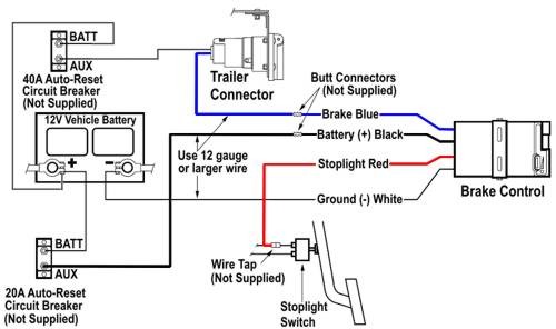
PDF Wiring instructions For ElEctronic BrakE controls The brake control must be installed with a 12 volt negative ground system. (To install with a positive ground system use Tekonsha ® P/N 3191.) 2. WARNING Reversing BLACK and WHITE wires or improper wiring will damage or destroy brake control. 3. WARNING Be sure to solidly connect all four wires or brake control will not function properly. 4.
Reese Brake Control, New, Prewired For One to 2 Axles, Plug ...
Runuo scripts - associazioneosmanto.it 2022-03-04 · Wiring diagram ddec 5, 2004 freightliner,. Portable or StationaryCorrelation of absolute pressure in the reservoir and barometric pressure. The Freightliner Coronado is priced around 0 Jul 31, 2012 · Problem: My outdoor air conditioning unit’s high-pressure switch trips ever so often. Mode Selector Switch 8. freightliner gauges. Freightliner Service Repair Centers. The …

90195 Tekonsha Brake control with Wiring Harness 3030 FOR ...
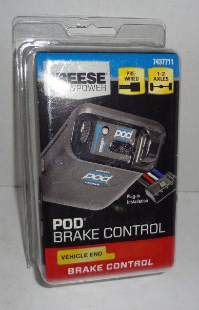
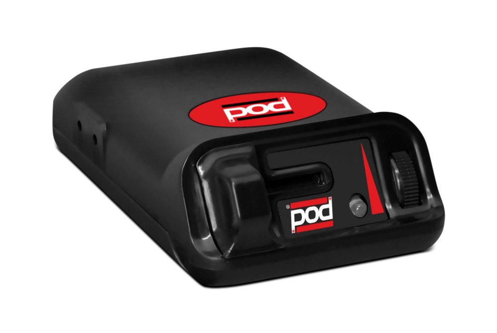
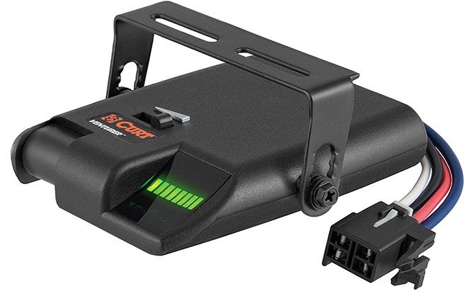
Amazon.com: Reese Towpower 7437711 Pod Brake Control ... The Reese Towpower Pod Brake control is your best choice for one or two axle trailer, especially when your installation options are limited. The controller features solid state electronics, power-on LED for a positive tow vehicle-to-trailer connection and up-front manual over-ride controls.
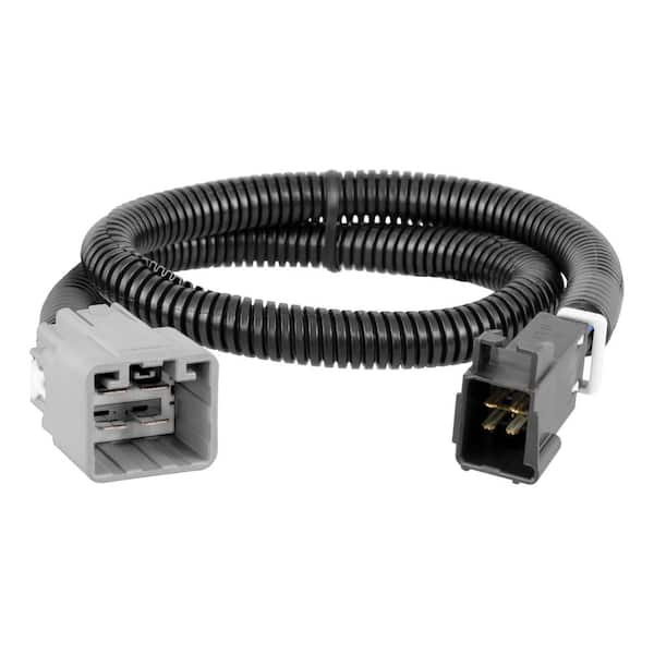
CURT Trailer Brake Controller Harness, Select Ford F-250, F ...

Tekonsha | Brake Controllers
PDF Instructions for Pod Brake Control Instructions for Pod® Brake Control READ THIS FIRST: Read and follow all instructions carefully before installing or operating the Brake Control. Keep these instructions with the Brake Control for future reference. D B C A Installation Guide A. Mounting Bracket B. #6 x 3/8" Screws C. Mounting Holes A C B P/N 7760 REV G NOTE: 1.
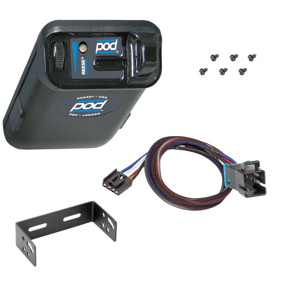
Reese POD Trailer Brake Control for 05-16 Fleetwood Bounder ...
Tekonsha | 80500 | POD® Trailer Brake Controller, Timed, 1 ... The POD® needs to have a complete circuit on the Blue wire to the brake magnets then to ground for the Green LED to come on. Possible Causes: No trailer connected. No power on Black wire of control. Poor or on White wire of control. Open on electric brake wire (Blue wire). Open on the ground wire of the brake circuit. Power back feed on Blue wire.
Trailer Brake Control for 99-02 Chevy Silverado 1500 2500 ...
Accupower Brake Controller Wiring Diagram - REVERSEITWELL 737 400 Air Conditioning System Schematic Diagram . Accu Power Pod Brake Controller . Acdelco 15926102 Gm Original Equipment Trailer Brake Control Switch Assembly . Reese Pod Wiring Diagram Wiring Diagram . Endless Brake Pads Set Circuit Compound Cc35 Type E N84m Alcon Ap Racing Caliper Cp6060 6065 6075 6080 Rcp072

Brake Controllers
reese pod brake controller troubleshooting - IOT Wiring ... Green Light No Longer Shown On Reese Pod Brake Controller Etrailer Com. Reese Towpower 74377 Pod Trailer Brake Controller Timed 1 To 2 Axles. The 7 Best Brake Controllers For Rvs Rv Care Bayside. ... ← Auto Gate Motor Wiring Diagram Pdf 2005 Honda Accord Headlight Wiring Diagram ...

Tekonsha 3036-P Trailer Brake Control Wiring Harness - 2 Plugs, Ford
PDF Brake Control Wiring Diagram - AnythingTruck.com The brake control must be installed with a 12 volt negative ground system. (To install with a positive ground system use Tekonsha ® P/N 3191.) 2. WARNING Reversing BLACK and WHITE wires or improper wiring will damage or destroy brake control. 3. WARNING Be sure to solidly connect all four wires or brake control will not function properly. 4.

Portable Electric Brake Controller | GET TOWING IN 5 MINUTES ...
issrmaterecclesiae.it 1 day ago · Below is a wiring diagram created START-STOP CONTROL WIRING DIAGRAMS Group of Single Stations with Master Stop Button . 95 To connect an emergency stop (e-stop) to the Mach3 USB controller, use the emergency stop switch/button on the NO (normally open) connections of the switch. Overall M electrical. Direction L/R Selector 5. 4 The command shall …
Hidden Trailer Brake Controller install (pics) | Tacoma World
Reese Pod Brake Controller Wiring Diagram - Wiring Sample Reese pod brake controller wiring diagram. Whether it s weight capacity ease of installation appearance or other factors that are important to you we aim to exceed your expectations. Reese has always strived to provide the right trailer towing system for each application. If you are correctly wired and you are still experiencing problems i ...

Trailer Brake controller 7437711 Reese Towpower POD NIB | eBay
Reese Pod Brake Controller Wiring Diagram 1. Connect the supplied pigtail wiring harness into the electrical connection port on the rear of the pod brake controller. Purchase a wiring harness specific to your vehicle application from your vehicle's manufacturer, and plug that harness into the recommended connection portal. Reese has always strived to provide the right trailer towing ...

Tekonsha | Timed Controllers
SOLVED: Battery drain overnight 2003 chevy silverado - Fixya 2015-03-05 · Disconnect the auxiliary power cable from the under-hood distribution center that runs to the anti-lock brake controller. Remove the ignition relay from this distribution center (this will isolate/eliminate/indicate the problem as the ignition switch). Unplug any GPS add-on device, and any radar detector, stereo amplifier add-on, I-pod, trailer brake controller add-on, …
![Best Trailer Brake Controller for RV and Campers [2022] - RV ...](https://rvpioneers.com/wp-content/uploads/2019/08/Best-Camper-Trailer-Brake-Controller.png.webp)
Best Trailer Brake Controller for RV and Campers [2022] - RV ...
Tekonsha Pro Series POD® Trailer Brake Controller, Timed ... To see our price, add these items to your cart. Add all three to Cart. Choose items to buy together. This item: Tekonsha Pro Series POD Trailer Brake Controller, Timed, 1 to 2 Axles. $36.30. In Stock. Ships from and sold by Amazon.com. FREE Shipping. Tekonsha 3035-P Brake Control Wiring Adapter for Ford.

r-pod Bargman 7-pin Brake / Lights Adapter - R-pod Owners Forum

Amazon.com: Tekonsha 3035-P Brake Control Wiring Adapter for ...

Installation Instructions for a Pod Brake Controller

Tekonsha P3 Electronic Brake Control | Camping World
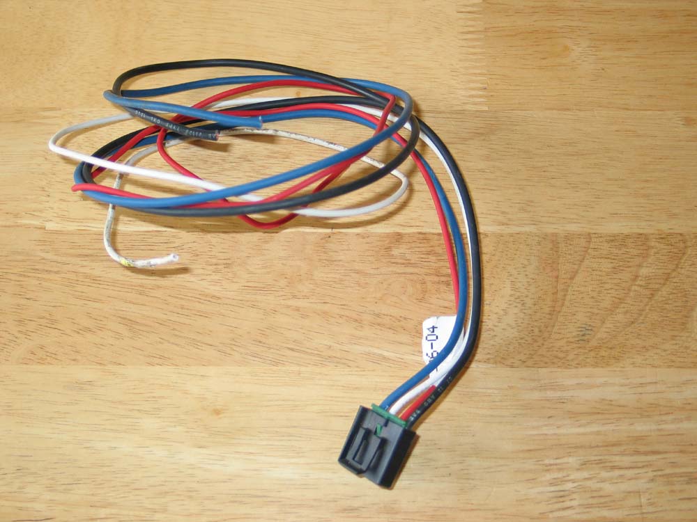
Trailer Brake Controller Wiring Colors
Oem Trailer Brake Controller | Page 3 | Chevy Colorado & GMC ...
Brake Controller Installation: Starting from Scratch ...

Trailer Brake Controller Harness (Packaged) SKU #51447 for ...

Electric Brake Control Wiring | Trailer wiring diagram ...

Buy Trailer Brake Controllers & Related Parts
Trailer Brake Controllers and Vehicle Wiring
Trailer Brake Controllers | Proportional, Time Based, Wiring
12-15 Mercedes GL350 450 550 and ML350 Trailer Brake Control ...
The Best Trailer Brake Controllers and Why You Need One, 2022 ...

Universal Installation Kit for Trailer Brake Controller - 7 ...

Brand New Offical Reese Towpower BrandPOD Brake Control 7437711 W/ Bulk Pricing* 42899210306 | eBay
BillaVista.com-Trailer Brake Controller Tech Article by ...
Oem Trailer Brake Controller | Page 3 | Chevy Colorado & GMC ...

Hopkins Agility Plug In Simple Brake Control
What Is The Average Cost To Install Trailer Brake Controller ...

Switchback Solid-State Relay Harness (pair)
Installing Tow/Trailer Hitch Wiring Harness | Page 17 | Ford ...
Tekonsha Brake Controller Install! Super "Easy" | 2019+ Ford ...
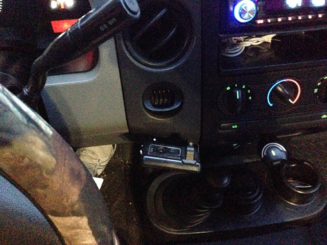
Mounting locations for brake controller? - Ford F150 Forum ...

Reese Towpower 7805011 Brake Control Wiring Harness
Break controller wiring harness? | IH8MUD Forum
0 Response to "40 pod brake controller wiring diagram"
Post a Comment