40 pulley system free body diagram
PDF Physics Kinematics, Projectile Motion, Free-Body Diagrams ... pulley. Then they push safe out of the window. What is the safe's speed when it hits the truck? What is the force exerted on the truck by the safe? µ=.5 Rotational Motion 1. Draw a diagram of the object or objects that will be the system to be studied. 2. Draw a Free-body diagram for the object under consideration. 3. Free Body Diagram (how do you make free body ... - YouTube Making accurate free body diagrams for a system of blocks connected by string and pulleys is an important step towards writing the correct equations of motio...
Pulley Free Body Diagram - Physics Forums fbd free body diagram pulley system statics Sep 20, 2015 #1 Alison A. 86 2 Homework Statement A collar with a pulley slides on a frictionless vertical bar GH. A string A B C D is wrapped around, where portion AB of the string is horizontal. A spring with 2.5 lb/in. stiffness is placed between the collar and point H.

Pulley system free body diagram
Answered: Draw a free body diagram (fbd) for m1… | bartleby Draw a free body diagram (fbd) for m1 for the case where it is released from rest. Use the notation shown in class, F 2on 1. Draw your force vectors to scale so you can tell the direction of m1’s acceleration is to the right. Clearly indicate which direction you are choosing as positive for the horizontal and vertical directions. Write out the two equations from Newton’s Second Law ( … Pulley in Physics - pulley tension problems with solution ... Coordinate systems and Common acceleration - Pulley in Physics. For an ideal pulley, the tension is the same throughout the rope (therefore the same symbol T in both diagrams). This is generally a common consideration for pulley tension problems. The acceleration a of each subject is indicated. The cart accelerates to the right when the ... Free Body Diagram Questions and Answers - Study.com Free Body Diagram Questions and Answers. Get help with your Free body diagram homework. Access the answers to hundreds of Free body diagram questions that are explained in a way that's easy for ...
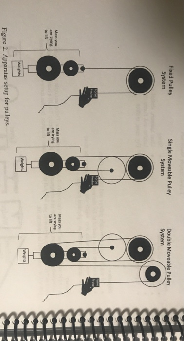
Pulley system free body diagram. PDF Mechanical Advantage with Pulleys - LEAPS Draw the free body diagram for the bottom pulley. Free Body Diagram b. Assuming a person weighs 600N, calculate the tension necessary to maintain equilibrium. c. In real-life estimate the force necessary to lift this person at a constant velocity. Extra Credit Free Body Diagram of CablePulley System C The Free Body Diagram of Cable-Pulley System C The system is held in equilibrium at angle Θ by the tension, T. 30º *Click to see solutions A cable connects pulley A to the ceiling at point C. A Θ T Ignore the weight of the pulley and the cable. B FBD of pulley A TAC y x 30º A TAC= The tension FROM the supporting cable (at 30º) ON the pulley. PDF 5-4 A System of Two Objects and a Pulley - WebAssign system of two objects and a pulley. Figure 5.7: Free-body diagrams if there is no friction. (a) The free-body diagram of the red box. (b) An appropriate coordinate system for the red box. (c) The free-body diagram of the red box, with force components aligned with the coordinate system. (d) and (e), a free-body diagram and coordinate system for ... Two-Body Problems - Physics Classroom The pulley system analyzed here is sometimes referred to as an Atwood's machine. The problem-solving approach is the standard approach that will be used throughout this page in order to solve for the two unknowns. It will be repeated in Example Problem 2 in order to solve what is commonly referred to as a modified Atwood's machine problem. Example Problem 2. Consider …
Free Body Diagram -Study Material for IIT JEE - askIITians We can draw the free body diagram of bob at a as shown in figure 1.43. The force acting on the bob is it's weight mg and tension T of the string. Tenstion T is resolved in two components T cos θ and T sin θ as shown in figure 1.43. we can write the equation of motion. T cos θ = mg T sin θ = mv2/r. 5.7 Drawing Free-Body Diagrams | University Physics Volume 1 Figure 5.32 (a) The free-body diagram for isolated object A. (b) The free-body diagram for isolated object B. Comparing the two drawings, we see that friction acts in the opposite direction in the two figures. Because object A experiences a force that tends to pull it to the right, friction must act to the left. Because object B experiences a component of its weight that pulls it to the left ... PDF Activity 2.1.3 Free Body Diagrams Create a FBD for the pulley system pictured below. Different types of support reactions •Cable, rope, or chain •Pin •Roller •Built-in end -Cantilever Free Body Diagram Reactions To aid in completing free body diagrams, connections are often identified with letters Cable, rope, chain -Replace with a tension force only. Cable Support 5.7 Drawing Free-Body Diagrams – University Physics Volume 1 Convert the free-body diagram into a more detailed diagram showing ... A block rests on the table, as shown. A light rope is attached to it and runs over a pulley. The other end of the rope is attached to a second block. The two blocks are said to be coupled. Block . exerts a force due to its weight, which causes the system (two blocks and a string) to accelerate. Strategy. We …
PDF Simple Machine Prelab Draw the free body diagram on for ... Pulley System w load (Newton) w input (Newton) d load m d input m Mechanical advantage M adv Efficiency E Atwood Movable Compound Your Design . Analysis: 1. Draw the Free-body diagram on the input weight in Fig 2, and draw the free-body diagrams from the load weight for Figs 3, 4, and 5. 2. Explain why the Efficiency numbers were all less than ... Pulley system free body diagram - YouTube About Press Copyright Contact us Creators Advertise Developers Terms Privacy Policy & Safety How YouTube works Test new features Press Copyright Contact us Creators ... PDF Physics 20 Lesson 18 Pulleys and Systems masses that are connected and accelerating together. Using the pulley system illustrated to the right below as an example, the basic method for discussed. As in Lessons 15, 16 and 17, the basic method is to draw a free body diagram of the forces involved, write an expression for the net force, and then solve for the acceleration. In a pulley ... Pulley Systems Diagrams - Find The Business Information ... The diagram below shows a pulley attached to a beam. The rope is 'pulled' on the effort side and the weight being lifted is on the right hand side, called the 'load'. In general a single pulley is useful as it allows the labourer (shown right) to lift the weight without ... More Info At technologystudent.com ›› United Standard Water System

Tension, String, Forces Problems with Solutions
Solved Drawing free body diagrams and writing equilibrium ... Drawing free body diagrams and writing equilibrium equations For each of the following pulley systems, draw separate free body diagrams for all pulleys 1 through 6, then write the sum of the forces in the x and y directions for the free body diagrams you drew. Assume all pulleys are frictionless, massless, and have a negligibly small radius.
Two-Body Problems
Pulley Problems and Constraint Equation | Physics Pulley ... Now, from the Free Body Diagram (FBD): The equation of force from FBD: M ... This is an example of a Fixed Pulley System. CASE – 2. Consider the following pulley system: First, we have to relate the tension between string 1 & string 2, Consider FBD of pulley B: 2T 1 – T 2 = M B.a B. 2T 1 = T 2. . . . . . . . . (4) (Since the pulley is massless) Now, Consider the …

How to Solve a Physics Problem Undergrads Usually Get Wrong ...
Solved C. Torque and angular acceleration. 1. Draw an ... 1. Draw an extended free body diagram for the pulley and pulley AT hanger system (see the diagrams to the right) acceleration (but not at g), the linear acceleration is related to the angular acceleration byand torque is related to force by tr', we have. mass hanger 2. Remembering that the falling weight is undergoing

Pulleys - Physics for K-12 - OpenStax CNX
MET211_Unit_2_Practice_Clearwater_Scott.docx - Course Hero Determine tension T for the pulley system shown in Figure P4-26. Show appropriate free-body diagrams to support your calculations. T + T 1 = 200 lb ; 2 T + T 2 − T 1 = 0 ; T 1 = 2 T + T T + 2 T + T 2 = 200 lb 2 T − T 2 = 0 T 2 = 2 T T + 2 T + 2 T = 200 lb 5 T = 200 lb T = 40 lb 2

Boy on a pulley — Collection of Solved Problems
5.7 Drawing Free-Body Diagrams – General Physics Using ... Convert the free-body diagram into a more detailed diagram showing the x ... A block rests on the table, as shown. A light rope is attached to it and runs over a pulley. The other end of the rope is attached to a second block. The two blocks are said to be coupled. Block [latex]{m}_{2}[/latex] exerts a force due to its weight, which causes the system (two blocks and …

Belt and Pulley Devices, the Simple Answer.
What is Free Body Diagram in Physics - Definition, Purpose ... Assuming no friction in the pulley system. Free body diagram examples calculation equations Find out the value of force in newton which should be applied to the rope for moving the metal block up the incline. Process to Draw Free Body Diagram Step 1: Draw the object Draw the object on which the force is applied without any vectors or arrows.
Solved 2. draw a free body diagram for the “force probe” in ...
2.972 How an Elevator Works - Massachusetts Institute of ... Free body diagram of the pulley system: The following analysis has been done for steady state (no acceleration )operation. The force on the driving pulley is equal to the difference of the two exerted tensions on each side. On one side, this force is equal to W e and on the other side, it is W c.

Pulley and Cables Free Body Diagram in 2 Minutes! (Example)
Tension, String, Forces Problems with Solutions Several problems with solutions and detailed explanations on systems with strings, pulleys and inclined planes are presented. Free body diagrams of forces, forces expressed by their components and Newton's laws are used to solve these problems. Problems involving forces of friction and tension of strings and ropes are also included.. Problem 1

A mass M is held in place by an applied force F and a pulley ...
Pulley - Wikipedia Free body diagrams. The mechanical advantage of a pulley system can be analysed using free body diagrams which balance the tension force in the rope with the force of gravity on the load. In an ideal system, the massless and frictionless pulleys do not dissipate energy and allow for a change of direction of a rope that does not stretch or wear.
Solved I can draw the free body diagram and I believe the ...
Free Body Diagrams, Tutorials with Examples and Explanations A) free body diagram for block m 1 (left of figure below) 1) The weight W1 exerted by the earth on the box. 2) The normal force N 3) The force of friction Fk 4) The tension force T exerted by the string on the block m1. B) free body diagram of block m 2 (right of figure below) 1) The weight of the block W2 2) Tension T '.

Pulleys - Physics for K-12 - OpenStax CNX
PDF ENGR-1100 Introduction to Engineering Analysis FREE-BODY DIAGRAMS (Section 5.2) 2. Show all the external forces and couple moments. These typically include: a) applied loads, b) support reactions, and, c) the weight of the body. Idealized model Free-body diagram (FBD) 1. Draw an outlined shape. Imagine the body to be isolated or cut "free" from its constraints and draw its outlined shape.
An object of mass 16 kg is held in place by an applied force ...
Types Of Pulley:Exhaustive Insights Free body diagram of Fixed Pulley Working of a fixed pulley When you pull the rope on one side, say downward, the other side of the rope moves in the upward direction. The force that you apply to pull the rope downward is equal to the force that you exert to lift the same object by your hand. In this case, the direction of force changes.

Free-body diagram of wheel 1, wheel 2, the pulley and the ...
Free Body Diagram: Definition, Purpose, Examples, Steps ... In a Free-Body Diagram, the object is represented by its expression, usually a line, box, or a dot. The force vectors that act upon the object are represented by a straight arrow while moments are represented by a curved arrow around their respective axis as shown in the image below where a force is acting at B and a moment acts around A.

A5_SSA18 - Physics 5 Labs
Subject: Forces (Free Body Diagrams; F = ma) Draw one Free Body Diagram for each object (see below for what is a good FBD). 2. Break the forces up into components. 3. For each object and each direction, write down Σ F = (sum of forces) = ma . 4. Solve this set of equations. If there are N unknowns then you need N equations. Often you need to include additional equations like fk =µkFN to solve the problem completely. …

a) A two-pulley belt drive. (b) Free body diagrams of the ...
Draw a free body diagram for this pulley system acting on ... Draw a free-body diagram showing all the forces acting on the mass m shown in Figure 2. 2. From the earlier description, diagrams and the laws of Physics, show that the motion of the system in Figure 2 can be described by the LCCDE (linear...
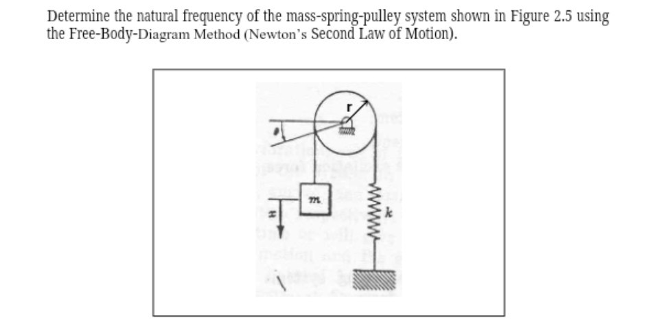
Solved Determine the natural frequency of the | Chegg.com
PDF Modeling Mechanical Systems - California State University ... • Establish inertial coordinate system • Identify and isolate discrete system elements (springs, dampers, masses) • Determine the minimum number of variables needed to uniquely define the configuration of system (subtract constraints from number of equations) • Free body diagram for each element

Simple Machines | Simple machines, Pulley, Block and tackle
Basic Mechanics - Rice University Figure 3.1:Free Body Diagrams In Figure 3.1the lamp was represented by a simple dot. We assumed that the lamp was rigid and that a downward force applied at one particular spot on the lamp would yield the same result as a similar downward force applied at a different place on the lamp. Actually, in order for a force of equal

Solved a) Draw the free body diagram for pulley A. b) Draw ...
PDF 4.3. Tension and Pulleys Pulleys: Demonstration 1. How might a pulley change tension? 2. What would the free-body diagram of the balance of forces be for a rope and a pulley: a. For the rope turned 90 degrees? b. For the rope turned 180 degrees? 3. Experiment!
05 - Free Body Diagrams, Pulleys and Friction - YouTube
2015 Chevrolet Serpentine Belt Diagrams — Ricks Free Auto ... 06.11.2018 · 2015 Chevrolet Equinox Serpentine Belt Diagram 4-Cyl. 2.4L. Serpentine K060780 Idler Pulley 36442. 2015 Chevrolet Equinox Serpentine Belt Diagram V-6 3.6L. Serpentine K060950 Tensioner Assy. 38397 Idler Pulley 36110 Alt. Decoupler Pulley 37206P . 2015 Chevrolet Express Serpentine Belt Diagram V-8 4.8L. Serpentine; W/105A. Alt. K060923HD or …
How Do Pulleys Redirect Forces? : r/AskPhysics
Free Body Diagram Questions and Answers - Study.com Free Body Diagram Questions and Answers. Get help with your Free body diagram homework. Access the answers to hundreds of Free body diagram questions that are explained in a way that's easy for ...

Find the motion of mass, m, of the mass-pulley system when it ...
Pulley in Physics - pulley tension problems with solution ... Coordinate systems and Common acceleration - Pulley in Physics. For an ideal pulley, the tension is the same throughout the rope (therefore the same symbol T in both diagrams). This is generally a common consideration for pulley tension problems. The acceleration a of each subject is indicated. The cart accelerates to the right when the ...

Part 4
Answered: Draw a free body diagram (fbd) for m1… | bartleby Draw a free body diagram (fbd) for m1 for the case where it is released from rest. Use the notation shown in class, F 2on 1. Draw your force vectors to scale so you can tell the direction of m1’s acceleration is to the right. Clearly indicate which direction you are choosing as positive for the horizontal and vertical directions. Write out the two equations from Newton’s Second Law ( …
Connected system - Physics Stack Exchange

Statics eBook: Equilibrium & Free Body Diagrams

Engineering Mechanics - ppt download
Two-Body Problems

The Free Body Diagrams Of The Two Hanging Masses Of - Newtons ...

Example 10
Horizontal pulley
EN4: Applications of Newton's Laws

Free-body diagram of the pulley and the associated vector ...
Solved] Determine the tension Tin the cable for each pulley ...

Statics eBook: Equilibrium & Free Body Diagrams
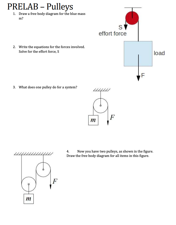
Solved PRELAB – Pulleys 1. Draw a free body diagram for the ...

How to Draw a Free Body Diagram - Simply Supported Beam with a Point Load

(3/8) Simple FBD with Pulley

Free Body Pulley 2
Solved Draw the Free Body Diagram of the examined system and ...
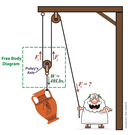
Free Body Diagram | Engineering Expert Witness Blog

Tips And Tricks to Solve The Mechanics Problems Using Free ...
0 Response to "40 pulley system free body diagram"
Post a Comment