41 chilled water air conditioning system flow diagram
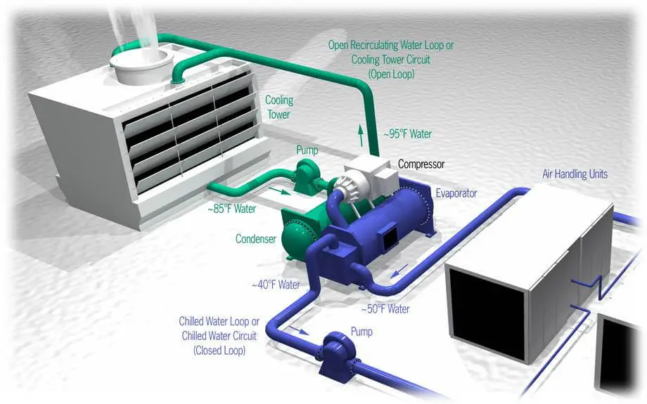
HVAC Chilled Water Distribution Schemes - CED Engineering chilled water flow through the cooling coil is restricted (in response to supply air temperatures to the space) but the total quantity returned to the chiller remains constant. Figure below shows the schematic of the constant-flow rate primary system. Chilled Water Air Conditioning Principles And Applications How Chilled Water Air Conditioning Works. Chiller. The chiller is the section of the system where an exchange of heat occurred between the water that goes to the building and the evaporator. The water leaves the chilled water evaporator at 45°F or 7°C. This chilled-water is then circulated through the entire building by the use of a pump.
Centrifugal Chiller - Fundamentals - Energy-Models.com Leaving chilled water temperature 44 o F; Chilled water flow rate 2.4 gpm/ton; Entering condenser water temperature 85 o F; Condenser water flow rate 3.0 gpm/ton; 0.0001 evaporator fouling factor and 0.00025 condenser fouling factor; The temperature change in the fluid for either the condenser or the evaporator can be described using the ...

Chilled water air conditioning system flow diagram
Chilled-Water Systems One of the Systems Series / Air ... and pipes. The water passes through the tubes of coils to cool air in an air conditioning system, or it can provide co oling for a manufacturing or industrial process. Systems that employ water chillers are commonly called chilled-water systems. When designing a chilled-wat er system, one of the first issues that must be Flow chart of the air-cooled water chiller components ... Download scientific diagram | Flow chart of the air-cooled water chiller components. from publication: Development of a water-mist cooling system: A 12,500 Kcal/h air-cooled chiller | Global ... Central Air Conditioning System Flow Diagram | Sante Blog Aug 07, 2018 · All About Reusing Old Central Air Systems. Hvac Cooling System For Data Centers Stmicroelectronics. See also Grilled Hut Pizza Melton Contact Number. Hitachi 6 Hp To 96 Vrf Variable Refrigerant Flow System. Hvac diagram standard heating air conditioning a simple air conditioning circuit and cycle diagram that you might centralized air ...
Chilled water air conditioning system flow diagram. Chilled Water System: Components, Diagrams & Applications Chilled water system diagram (photos) A chilled water system can be separated into two loops; a) chilled water loop and b) condenser water loop. The chilled water loop starts with the chiller followed by the AHUs and the chilled water pump (CHWP) before returning back to the chiller. Closed Loop Chilled Water System Pressure - aircondlounge Closed loop chilled water system diagram (not moving) From the above diagram, the chilled water inside the pipe is pressing down harder on the gate valve and the AHU that is located on the lower floor than the chiller on the upper floor. The pressure exerting on the gate valve is: Ps = ρgh Ps = (1000) (10) (70) Ps = 700,000 Pa PDF Comprehensive Chilled-Water System Design Chilled-water systems can be efficient by design, with easy to understand controls. Components The above graphic depicts five "loops" commonly used in a chilled-water system to remove heat from zone or process loads. This system comprises one or more chillers, cooling tower(s), condenser-water pumps, chilled- Building Drawing Software for Design Registers, Drills and ... The vector stencils library "HVAC control equipment" contains 48 HVAC symbols. Use it for drawing HVAC systems diagrams, heating, ventilation, air conditioning, refrigeration, automated building control, and environmental control design building plans and equipment layouts.
Chilled Water Systems - Engineering ToolBox Chilled water system equations - evaporator and condenser flow rates. In a chilled water system the water is cooled down to 40 - 45oF (4 - 7oC) by an centralized evaporator, distributed throughout the building in pipes and connected locally to air condition cooling units wherever needed. Thermodynamics Questions and Answers - Study.com A water mixing system initially contains 5000 lb of liquid water. The tank has two inlets of hot water and cold waer having respectively mass flow aes of … PDF Understanding Chilled Beam Systems - Trane Chilled Beam Systems Overview of Chilled Beam Systems Passive chilled beams (PCB). A PCB consists of a fin-and-tube heat exchanger, contained in a housing (or casing), that is suspended from the ceiling (Figure 1). Chilled water passes through the tubes. Warm air from the space rises toward the ceiling, and the air surrounding the chilled beam is PDF Best Practice Manual-hvac - Nredcap Refrigeration and air conditioning systems cover a wide variety of cooling applications, using both standard and custom-made equipments. Some commonly used applications are process cooling by chilled water or brine, ice plants, cold stores, freeze drying, air-conditioning systems etc.
PDF Applications Engineering Manual - Trane chiller's evaporator and condenser and their relationship to the chilled-water system. For more details on the basic operation and components of a chilled-water system, consult another Trane publication, Chilled-Water Systems, part of the Air Conditioning Clinic Systems Series (TRG-TRC016-EN). Specific application considerations for PDF 9.2.8 Safety Chilled Water System 9.2.8.1 Design Bases SCWS flow diagram is shown in Figure 9.2.8-1—Safety Chilled Water System Diagram. Pipe diameters for the SCWS are based on limiting the flow velocity to a range of 4 to 10 ft/second for normal modes of operation that are expected to occur frequently. Refer to Section 12.3.6.5.9 for safety chilled water system design features which How a Chiller, Cooling Tower and Air Handling Unit work ... The chilled water enters the AHU/FCU and passes through the cooling coil (a series of thin pipes) where it will absorb the heat of the air blowing across. The chilled water heats up and the air blowing across it cools down. When the chilled water leaves the cooling coil it will now be warmer at around 12°C (53.6°F). Control sequences for chilled water systems - Consulting As the chilled water valve begins to open, the chilled water differential pressure transmitter senses a drop in system pressure. This sends a signal to the chilled water control panel and VFDs. The pumps are designed to operate in a parallel configuration. Currently a single pump is operating in response to water flow requirements.
Chilled Water Schematics - The Engineering Mindset
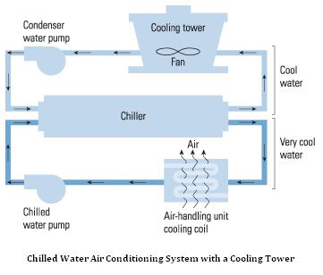
Chiller water systems - slideshare.net ADVANTAGES OF CHILLER WATER AIR CONDITIONING SYSTEMS • THE EVAPORATOR COOLS WATER TO ABOUT 45 .THAT CHILLED WATER IS PUMPED TO COOLING COILS IN THE AREAS BEING COOLED, AND A FAN DRAWS THE AIR IN THOSE AREAS THROUGH THE CHILLED WATER COILS, COOLING THE AIR. IN COMPARISON, WITH STANDARD AIR CONDITIONING, THE EVAPORATOR COIL DIRECTLY COOLS THE AIR.
Parametric investigation of a chilled water district cooling ...
PDF Optimizing Pumping Schemes In Air‐Conditioning Chilled water is pumped at a constant flow rate which is independent of the cooling load During part load conditions, which occurs op to 80% of the time, three way control valves at cooling coils are used to bypass the chilled water back to return line Chilled water mixes with return water from the cooling coils and this results in lower ...

Comparative research on different air conditioning systems ...
PDF Drawing 47W865-5, Rev. 14, 'Flow Diagram Air Conditioning ... flow diagram reference drawrngs. 478601 47w866 47%915 47020 47b920_ -31 series series series reactor building air-conditioning air conditioning chilled water rat ts bar nuclear plant tennessee valley authority q division of engineering design 31xl thru-31x4 inspected and approved for submitted recommen knoxville 7-//-7- 85 m 47w865—5
Water Cooled Chillers: HVAC Series Part II
How a Chilled Water System Works | HVAC Training Shop A chilled water system using an air-cooled chiller Water Cooled Chiller. Water-cooled chillers are almost always located inside of a building. They work almost the same way as air-cooled chillers. The difference is that they remove heat from chilled water by exhausting the heat to a second, isolated water line called the condenser water line.
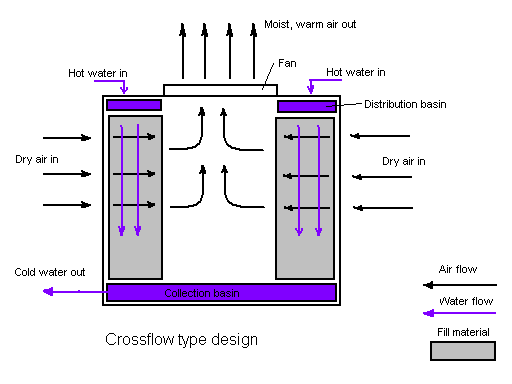
Cooling Tower
Chilled Water Schematics - The Engineering Mindset Apr 18, 2018 · The chilled water is generated and circulated in the primary side, the secondary loops will pull chilled water out of the header to cool the building and then dump the warm return back into the header. If the flow rate In the secondary side is low then some chilled water will flow into the secondary and some will recirculate back to the chillers.

Central Water Cooled Air Conditioner Manufacturers China ...
Windcatcher - Wikipedia The air is also evaporatively cooled when some of the water in the qanat evaporates as the hot, dry surface air passes over it; the heat energy in the air is absorbed as energy of vaporization. The dry air is thus also humidified before entering the building. The cooled air is drawn up through the house and finally out the windcatcher, again by the Coandă effect. On the whole, …
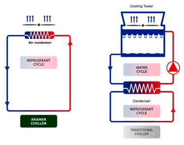
Air Cooled VS Water Cooled Chiller | ARANER
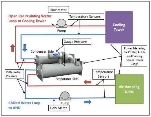
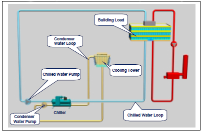
Chiller Application Guide - Daikin Applied Basic System Figure 1 shows a basic chilled water system with connected loads. The system consists of a chiller, cooling tower, building cooling load, chilled water and condensing water pumps and piping. This section will review each of the components. Chiller Basics The chiller can be water cooled or air cooled.

Air conditioning- Types, Diagram, Working, Applications
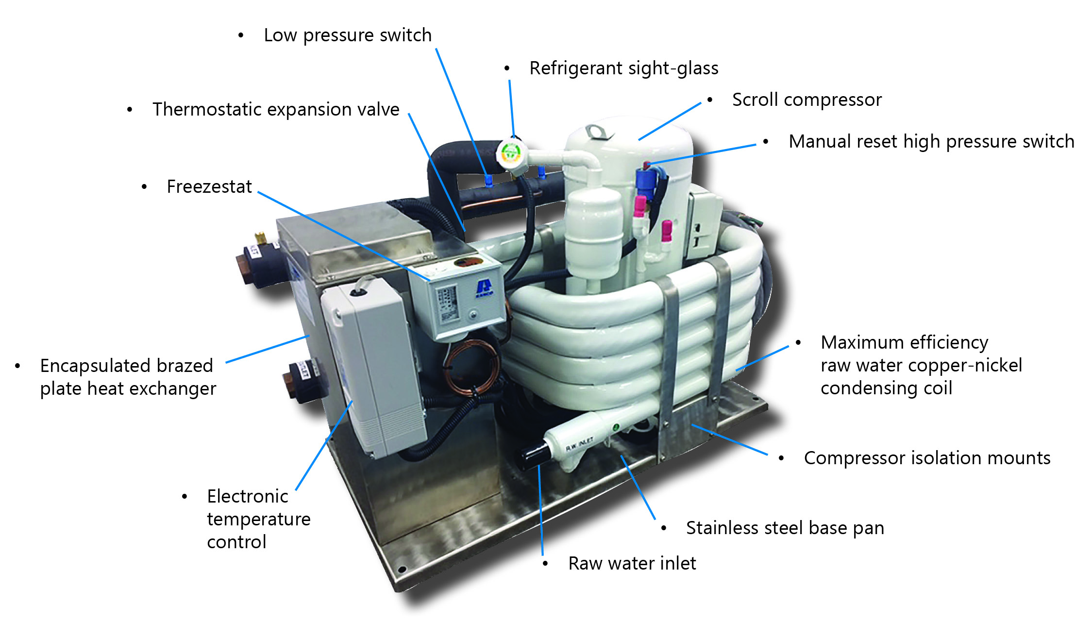
PDF Installation, Operation & Maintenance ... - Water Makers for the compressor, air handlers and pumps used in the chilled water system. HACR (heating, air conditioning & refrigeration) type circuit breakers are recommended for the ship's panel. HACR circuit breakers have a long delay to compensate for the electrical surge associated with compressor.
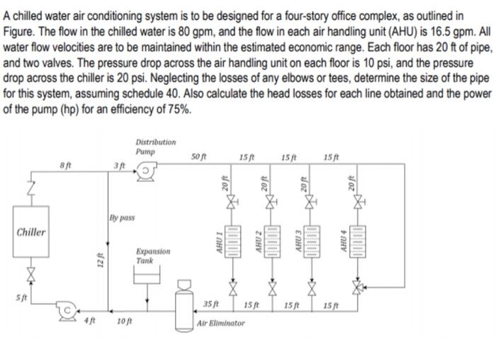
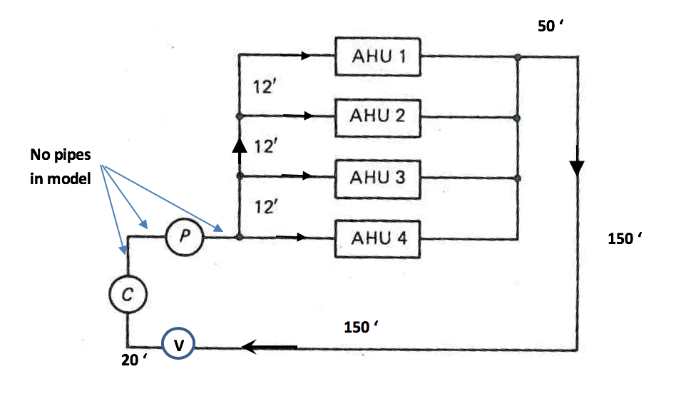
Solved A chilled water air conditioning system is to be ...
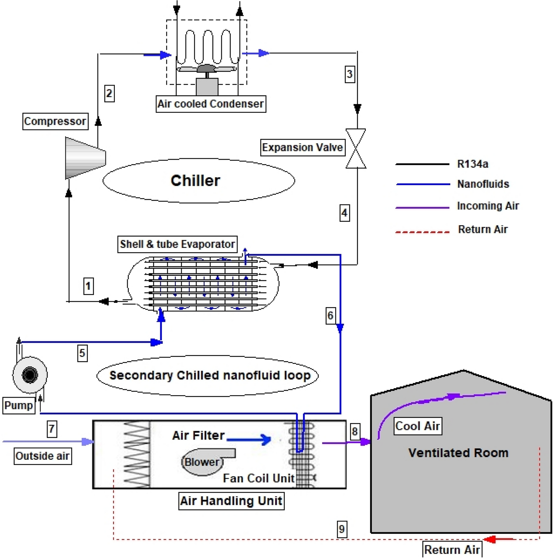
Schematic of a typical chilled-water system. | Download ... Figure 1 shows the schematic of typical chilled-water ventilation and air-conditioning system for commercial buildings with three main components: air handling unit, chiller and cooling tower.
The Basics of Chillers - HVAC Investigators
PDF Seawater Air Conditioning: A Basic Understanding operating mechanical chillers to keep the chilled water cold can be eliminated. The adjacent temperature profile illustra The basic concept of seawater air conditioning is to take advantage of available deep c A seawater air conditioning system is illustrated below. The buildings to the far right a
Design a chilled-water air-conditioning system for a | Chegg.com
Chilled Water System Presentation - HVAC Việt Nam COMMERCIAL BUILDING SERVICES FLOW THINKING 1.Low return water temperatures. 2.Robs chilled water from other coils at part load conditions. 3.Increases flow in primary piping. 4.Adds additional chillers on line. 5.Chiller performance is reduced. 3-way Valve System Deficiencies
Chilled water air conditioning
PDF Two-Pipe HVAC Makes a Comeback: An Idea Discarded ... - ACEEE A 2-pipe HVAC system is one that uses the same piping alternately for hot water heating and chilled water cooling, as opposed to a 4-pipe system that uses separate lines for hot and chilled water. Two-pipe originated 50 or 60 years ago as a cost-effective way to add air conditioning.

INSTALLATION OF AIR CONDITIONING SYSTEM * Archi-Monarch
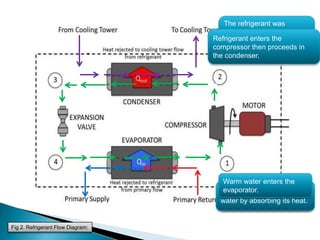
Water Chilled Airconditioning - SlideShare Fig 2. Refrigerant Flow Diagram: 12. Fig 3. Supply Air and Return Air Flow: 13. Advantages of Chilled Water Air-con. System: The evaporator cools water to about 45 .That chilled water is pumped to cooling coils in the areas being cooled, and a fan draws the air in those areas through the chilled water coils, cooling the air.
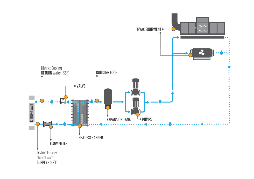
Cooling with Chilled Water / District Energy
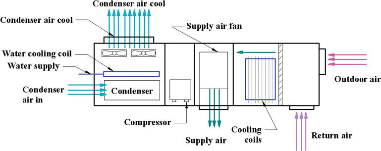
Centralised Air Conditioning System | Air Conditioning ... The cooling coils in air conditioning applications are of direct expansion type or of chilled water type. These are of finned tube construction in which the chilled water or the refrigerant gas flows through the tubes and the air is drawn over the surface of the tubes. The fins are provided for increasing the effective heat transfer area.
Water Chilled Airconditioning
Central Air Conditioning System Flow Diagram | Sante Blog Aug 07, 2018 · All About Reusing Old Central Air Systems. Hvac Cooling System For Data Centers Stmicroelectronics. See also Grilled Hut Pizza Melton Contact Number. Hitachi 6 Hp To 96 Vrf Variable Refrigerant Flow System. Hvac diagram standard heating air conditioning a simple air conditioning circuit and cycle diagram that you might centralized air ...
Chiller Plant Design | Energy-Models.com
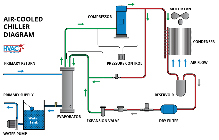
Flow chart of the air-cooled water chiller components ... Download scientific diagram | Flow chart of the air-cooled water chiller components. from publication: Development of a water-mist cooling system: A 12,500 Kcal/h air-cooled chiller | Global ...
Comprehensive Chilled-Water System Design
Chilled-Water Systems One of the Systems Series / Air ... and pipes. The water passes through the tubes of coils to cool air in an air conditioning system, or it can provide co oling for a manufacturing or industrial process. Systems that employ water chillers are commonly called chilled-water systems. When designing a chilled-wat er system, one of the first issues that must be
BEIJING SUNDA SOLAR ENERGY TECHNOLGOY CO., LTD.
How a Chilled Water System Works | HVAC Training Shop

SciELO - Brasil - Assessing the energy performance of VAV and ...

Sea Water Air Conditioning - Makai Ocean Engineering
Applied Sciences | Free Full-Text | New Developments and ...

What is Air Conditioning System? Diagram, Applications - ETechnoG
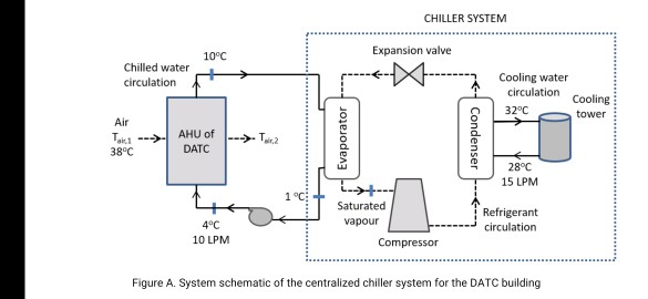
The DATC building houses a large hall for | Chegg.com
Chilled Water Air Conditioning System
What is HVAC System ? | HVAC system working Principle

Central air conditioning system working Animation

Schematic diagram of the chiller integrated VAV A/C system ...
Chilled Water Air Conditioning – Northern Lights Marine ...

Air Conditioning System - an overview | ScienceDirect Topics

Flow chart of the air-cooled water chiller components ...

Cooling and Chilled Water Systems - YouTube
Chilled-Water System Decisions
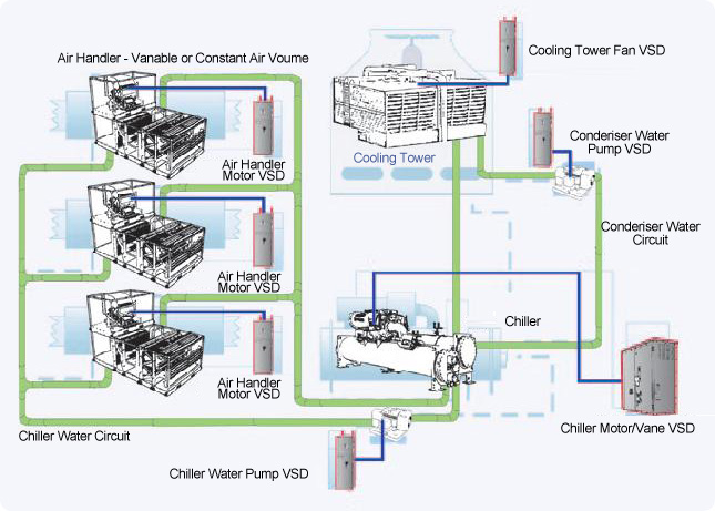
Energyland - Variable Speed Drives in Air-conditioning ...
Seawater Air Conditioning: A Basic Understanding

Find Chiller Diagram Cycle Chiller Diagram System stock ...
Chiller Application Guide Daikin AG 31-003

Five Basic Components of an Effective Air Conditioning System

Air-Cooled Chillers Are Back in Data Centers, and They Mean ...
Types of HVAC Systems | IntechOpen

What is Air Conditioning System? Diagram, Applications - ETechnoG
0 Response to "41 chilled water air conditioning system flow diagram"
Post a Comment