41 n64 controller wiring diagram
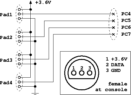
N64/Gamecube controller to USB adapter - raphnet.net But since Gamecube controllers use a very similar protocol, it was easy to support Gamecube controllers too. Gamecube and Nintendo 64 controllers both work at 3.3 volts. But on the USB bus, only 5 volts are available. For this reason, a voltage regulator is required. ... Here is a wiring diagram for the board: And finally, here are the gerber ... Joystick Controller - PCB and Wiring - slagcoin When wiring a PCB extracted from a pad controller, you need to solder a wire to the signal for each of the needed buttons, and one (or more) wire to each of the unique grounds used by those signals. The ground is usually shared around in the PCB and therefore can be shared among all the signals.
GitHub - po8aster/N64MIDIController: N64>MIDI - N64 ... See the Schematic section for wiring diagram. This project uses the same hardware as the Gamecube MIDI Interface. The only difference is that the controller connections for the N64 are only 3.3v, GND, and Data. The other controller connections in the schematic are not used. Parts list: Arduino Pro Micro - 5v Version; 220 Ohm Resistor x3 (1/4 ...
N64 controller wiring diagram
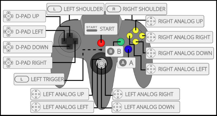
Nintendo Support: Nintendo 64 Controller Diagram Nintendo 64 Controller Diagram. Applies to: Nintendo Switch Family, Nintendo Switch, Nintendo Switch Lite, Nintendo Switch - OLED Model. You can use the enclosed USB charging cable to pair the controller with the console or to charge it. You can also connect it directly to an AC adapter. Takes a screenshot during play. Nintendo N64 - WordPress.com My system is single player only, although if you make your own, you can have up to 4 players (the N64 takes up to 4 controllers). moddedbybacteria said this on April 26, 2010 at 6:32 pm | Reply. is it possible you could enlarge the wiring diagram part for the step down regulator. James said this on April 22, 2010 at 3:59 pm | Reply N64 Controller Wiring Diagram The N64 controller uses only three wires to connect to the console. There's a ground wire, another wire that supplies +3, 6 volts of power, and a third wire that carries all data. Gamecube controller on diagram further x box models in addition xbox slim diagram further xbox usb wiring diagram as well as drill bit diagram moreover 5in1 x adapter ...
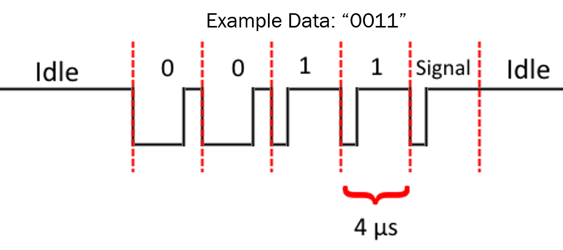
N64 controller wiring diagram. How N64 Works - HowStuffWorks The N64 controller uses only three wires to connect to the console. There's a ground wire, another wire that supplies +3, 6 volts of power, and a third wire that carries all data. The controller sends the information for each button in sequence, and then receives data back from the console. Games Cartridges are unique to Nintendo 64. Question - 64CC (PE); Only for OEM N64 Controller ... The joystick was working, until the controller itself stopped working fine, so I threw it in the trash. XD In short, you can replace the stock joystick on a generic N64 controller with a standard analog stick potentiometer without any custom chip or someting. Just don't get a controller that is going to die after a couple days (like me). How to Make a Portable Nintendo 64 (steps) : 8 Steps (with ... I included the wiring diagram for the voltage regulator above and the output of the voltage regulator goes to pin 3 on the back of the N64 board. Put the wires from the battery (power and ground/- and +) going to the N64 and the wires going to the voltage regulator in parallel to share the initial voltage from the battery. N64 Controller Diagram - Wiring Diagram Pictures The wiring for every generic N64 controller I've found thus far. I searched around but can't seem to find any wiring diagrams for this 4 wire. Use an Arduino With an N64 Controller: There are tutorials out there for using an NES controller with an Arduino, but Helpful schematics can be found here.
[Question] How would I wire up N64 controller buttons to ... I assume you want to attach arcade style buttons to a the N64 Controller so that you can attach it to a n64 console and control it. If that's the case see this diagram.You should just need to bring one side of the switch to the indicated test points and the other side of the switch to ground. N64 portable info -benheck.com Forums Joystick mod for third party controllers wiring diagram a picture about wiring the control! cartridge slot relocation guide! Adjustable regulator claculator how to replace an analog stick with a D-pad thread by g-force about fuses on the n64 board info by gannon on how to make an automatic n64 controller switchover thingy 3.3V converter diagram ... N64 Portable Kit Assembly Guide (Read First) | Downing's ... Wiring The Screen to the N64 Mother Board; Wiring The Tact Board; Part V - Controller & Control Stick Wiring. Wiring RDC's miNi64 V2.1 Controller Board; Wiring The PS3 Control Stick to RDC's miNi64 V2.1; Wiring The Memory Card to RDC's miNi64 V2.1 (optional) Part VI - Final Testing & Closing Up. Testing Power, A/V, Controller and ... Cb400t Wiring Diagram Cb400t Wiring Diagram. A wiring schematic for the Honda CB has been diagramweb.net can go to our downloads and grab yourself a copy! Download the Honda CB wiring schematic. view and download honda cbt shop manual online cbt motorcycle pdf manual chirco dune buggy wiring diagram, citroen c3 abs wiring diagram, chevy.
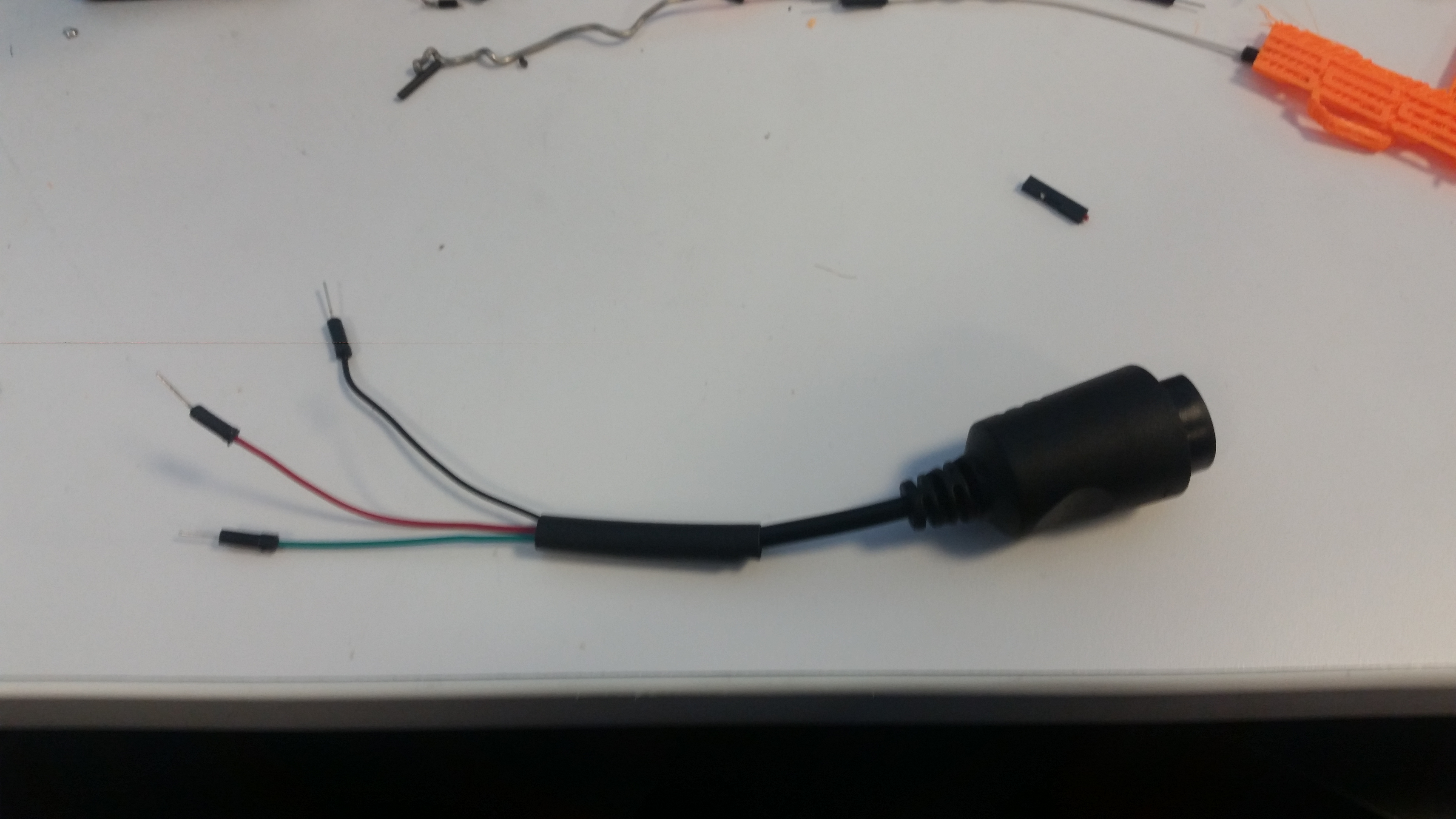
GitHub - LogicalUnit/N64_Bluetooth: Turn an N64 controller ... Stick 3 lengths of hookup wire into the controller's connector. I recommend bending the hookup wire to ensure good contact. Use heatshrink to hold the hookup wire in place. Solder the hookup wire to 3.3V, GND and D2. There should be a wiring diagram included with this project. Upload the sketch to the Arduino Uno. N64 Controller Diagram - wiringall.com 2. 6. Hints & cautions. The Nintendo 64 controller Wire wrap according the diagram on the right.N64 Controller Wiring Diagram ~ here you are at our site, this is images about n64 controller wiring diagram posted by Alice Ferreira in Diagram category on Nov 12, You can also find other images like wiring diagram, parts diagram, replacement parts ... N64 Joystick Rewiring Diagram? | The Official ModRetro Forums Now, coming back onto the scene, I've found that multiple sites have closed down and therefore a lot of my resources have been lost. So now, I'm wondering if anyone has or has a link to a wiring diagram to replace the n64 analog stick with an original gamecube joystick (NOT those plastic n64-gamecube replacement stick kits they sell). NES/SNES/N64/Gamecube controller to Wiimote circuit This circuit makes it possible to use a NES, SNES, N64 or Gamecube controller on a Wii or Wii-U by connecting to the wiimote as a classic controller. Ideal for Wii virtual console games on systems without gamecube ports. Features: Supports N64 controllers (Official and most 3rd party, including the Hori Mini) Support for Gamecube controllers.
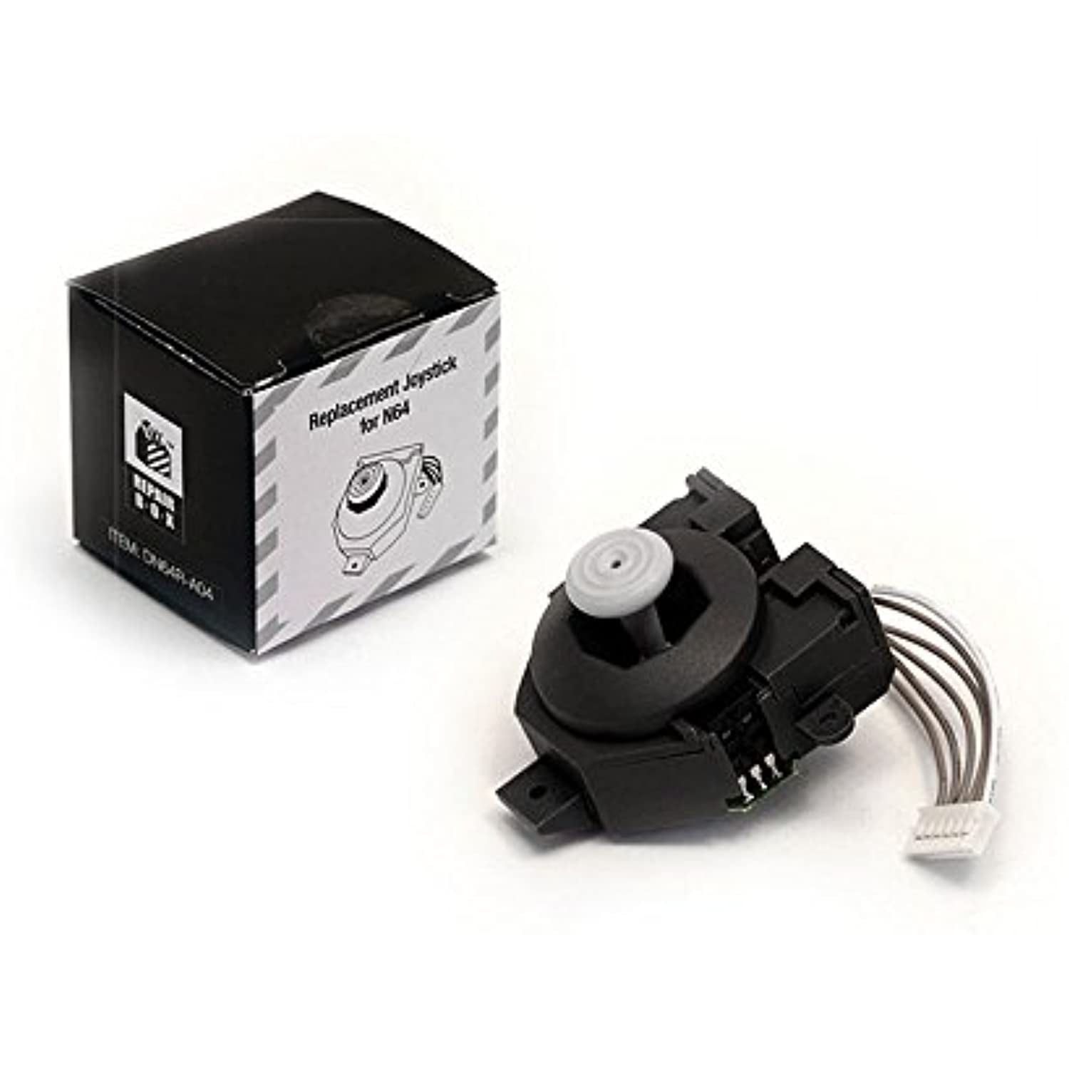
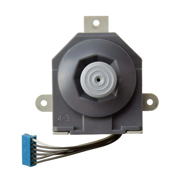
Hyperkin N64 RepairBox Replacement Joystick (N64 Style)
Wiring Diagram for tinkerBOY Controller V3.0 - tinkerBOY Home / Game Boy Zero / Wiring Diagram for tinkerBOY Controller V3.0 Posted on August 9, 2018 May 9, 2019 by tinkerBOY — 42 Comments Wiring Diagram for tinkerBOY Controller V3.0

How to Make a Portable Nintendo 64 (steps) | Trybotics
PDF Nintendo 64 Controller Diagram - Ruforum wiring diagram database nintendo 64 joysticks, nintendo 64 n64 accessories the gamesmen, does the n64 joystick really allow 360 degrees of control, n64 controller wiring diagram best place to find wiring, nintendo 64 power supply pinout and diy repair, gamecube to nintendo 64 controller converter, super

Part III – Power and Cart Slot Wiring | Downing's Basement
How-to-connect-Hook-Up-Nintendo-64-N64 - Gametrog STEP #5. Plug in a game and turn on the Nintendo 64, even if you don't see it on the TV yet. You should see the power light on the N64 light up (a good sign) and you should hear the disc spin-up. Doing this first will help in finding the right TV settings, when you're searching for the right channel or input and you see the game, you got it ...
Question - 64CC (PE); Only for OEM N64 Controller? | BitBuilt ...
N64 Controller Wiring Diagram - schematron.org N64 Controller Wiring Diagram. The controller is the primary user interface for the N With its trident shape, it is probably the most unusual design for a controller on the market today. I have a few old N64 controllers lying around and figured that it would The circuit I created for reading out the controller is shown in the schematic below.
![NINTENDO 64 (N64) CONTROLLER PLUG DISASSEMBLY [WARANTY VOID IF REMOVED]](https://i.ytimg.com/vi/DXnLhDPg23w/mqdefault.jpg)
NINTENDO 64 (N64) CONTROLLER PLUG DISASSEMBLY [WARANTY VOID IF REMOVED]
Can I modify an N64 controller to fix the inverted aiming ... You'll want to drill 6 tiny holes in the controller corresponding to the pins on the switch. I think I used a 1/16" drill bit. You can solder your longer wires to the switch before you push the switch through the holes on the controller, but you'll have to solder the "X" jumpers after it's in place unless you don't mind the switch not sitting flush on top of the controller.
Mapping buttons to n64 controller : r/RetroPie
N64/Snes/Nes controller to gamecube/Wii conversion project N64 controller to Gamecube/Wii adapter cable. Snes controller to Gamecube/Wii adapter cable (for more pictures, visit the pictures section) Preassembled N64 to Gc/Wii adapters available. ... Here are pictures and wiring diagrams: Very small PCB (S)NES Wiring diagram. N64 Wiring diagram.

Q81F Thumbstick Analog Stick for N64 3D Joystick Controller ...
Using gamecube joysticks with N64 controllers | The ... The original nintendo 64 controller has small square holes in the joystick, which breaks the laser inside the joystick shell, and then the laser counts the breaks and tells the n64 how far you've moved the controller. ... Here's the wiring diagram for the Joystick. Note that this is on the back of the board and 1-4 is from right to left on the ...
N64 to Gc/Wii PCB - User`s manual | Manualzz
Nintendo Switch Schematic Diagram - IOT Wiring Diagram Nintendo Switch Lite Teardown Ifixit. Nintendo switch schematic sd card voltage diagram info board and part numbers daniel ahmad 在twitter 上 i ve created repair gbatemp net joycon lite teardown ifixit schematics console related 64 av cable wiring ninty mobo the wonderful world of usb type c system dmg gbdevwiki diagrams service model 29 max wii playstation 4 diy super breadboard controller ...

N64 log - 17 - Wiring the controller: the principles, general method and tips
N64 Controller Wiring Diagram The N64 controller uses only three wires to connect to the console. There's a ground wire, another wire that supplies +3, 6 volts of power, and a third wire that carries all data. Gamecube controller on diagram further x box models in addition xbox slim diagram further xbox usb wiring diagram as well as drill bit diagram moreover 5in1 x adapter ...

Turn an N64 Controller Into a USB Gamepad Using an Arduino ...
Nintendo N64 - WordPress.com My system is single player only, although if you make your own, you can have up to 4 players (the N64 takes up to 4 controllers). moddedbybacteria said this on April 26, 2010 at 6:32 pm | Reply. is it possible you could enlarge the wiring diagram part for the step down regulator. James said this on April 22, 2010 at 3:59 pm | Reply
N64 Controller Interface | Mbed
Nintendo Support: Nintendo 64 Controller Diagram Nintendo 64 Controller Diagram. Applies to: Nintendo Switch Family, Nintendo Switch, Nintendo Switch Lite, Nintendo Switch - OLED Model. You can use the enclosed USB charging cable to pair the controller with the console or to charge it. You can also connect it directly to an AC adapter. Takes a screenshot during play.

Reading Nintendo 64 controller with PIC microcontroller ...

Wiring diagram Nintendo 64 controller Nintendo Entertainment ...
N64 on Leonardo - Programming Questions - Arduino Forum

Nintendo 64 av cable wiring diagram diagram base website ...

Nintendo Switch Controller Adapter for N64 Controller ...
N64 controller

NES Controller mit N64 Controller Innereien (ohne Analogstick ...
How N64 Works | HowStuffWorks

Conkers N64P wiring guide

Nintendo 64 Replacement Analog Stick 4 Wires Model
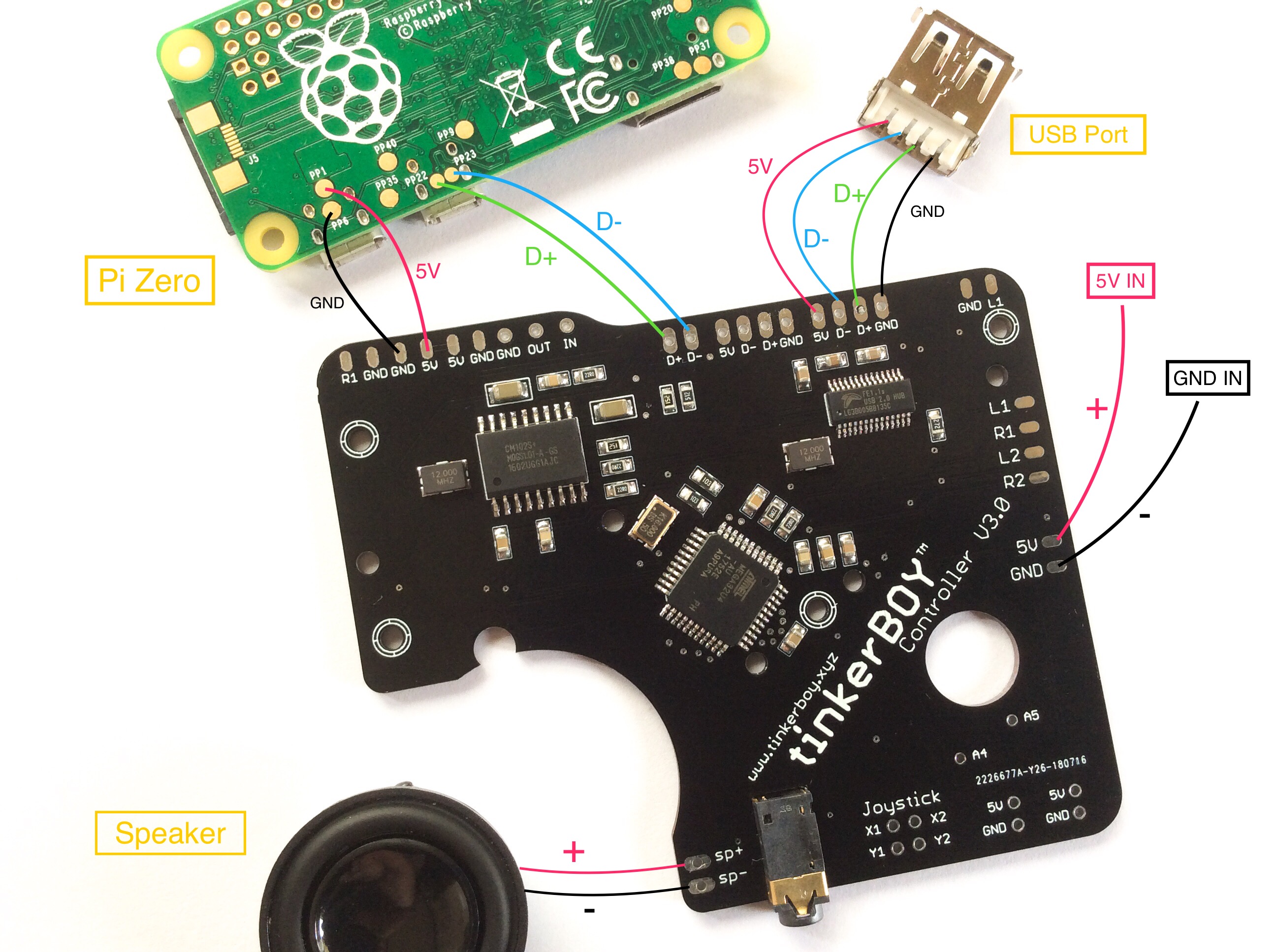
Wiring Diagram for tinkerBOY Controller V3.0 - tinkerBOY

RetroPie - N64 controller config setup

Reading Nintendo 64 controller with PIC microcontroller ...
Configuring 8Bitdo N64 Controller Mapping - Tutorial Australia

Reading Nintendo 64 controller with PIC microcontroller ...

Nintendo N64 |

Wiring diagram Nintendo 64 controller Nintendo Entertainment ...
N64 Controller Interface | Mbed

Nintendo 64, N64 - 64 Game Console Instruction Booklet | Manualzz
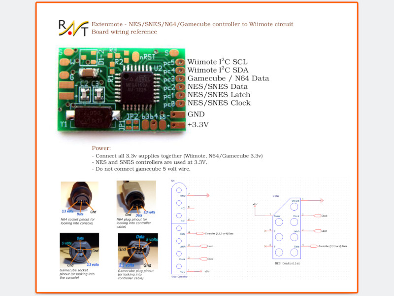
raphnet. - NES/SNES/N64/Gamecube controller to Wiimote circuit

Buy mcbazel rgb scart kabel für snes gamecube n64 ntsc Online ...

How to Make a Portable Nintendo 64 (steps) | Trybotics

Nintendo 64 Analog Stick - Ersatz NEU | Kaufen auf Ricardo

Amazon.com: Classic Linker N64 for Nintendo Wii and Gamecube ...

Nintendo Support: Nintendo 64 Controller Diagram

N64 Portable – Anthony Thomas

N64 Controller Joystick Thumbstick Repair for Nintendo 64 ...
Free Png N64 Png Png Images Transparent - Nintendo 64 ...
Original Controller Joystick Thumbstick Replacement ...

How-to-connect-Hook-Up-Nintendo-64-N64 — Gametrog
0 Response to "41 n64 controller wiring diagram"
Post a Comment