40 5 wire regulator rectifier wiring diagram
Regulator-rectifier only has 5 wires??? - KZRider Forum Any 3-wire aftermarket reg/rec with a total of 5 wires will be the hot wire as described (prolly the red wire), the black/white is prolly the ground and the yellows are stator connection wires. The reg/rec is a more modern type that senses voltage via the red wire. Rectifier Regulator Wiring Diagram - easywiring Regulator rectifier diagram here you are at our site this is images about regulator rectifier diagram posted by maria nieto in wiring category on may 08 2019. Provided below is an online pdf document for lamberts bikes 3 phase 6 wire regulator rectifier wiring diagram.
Briggs And Stratton Voltage Regulator Wiring Diagram 17.02.2019 17.02.2019 7 Comments on Briggs And Stratton Voltage Regulator Wiring Diagram shunt is designed to read voltage drops due to the resistance of the metal be- tween the Two wires of the same color feeding a regulator/rectifier is a rectified .

5 wire regulator rectifier wiring diagram
5 Pin Regulator Rectifier Wiring Diagram - easywiring 2 phase 5 wire motorcycle regulator rectifier wiring diagram pdf. We ve even included standard wire colours where appropriate. Lamberts bikes motorcycle part wiring diagrams. Simply plug the connector onto the 5 pins row and make sure that the pin assignments and wire assignments are matched correctly. M 3 2 2 2 phase 5 wire. 6 Pin Regulator Rectifier Wiring Diagram - Diagram Schemas Wiring Provided below is an online pdf document for lamberts bikes 3 phase 6 wire regulator rectifier wiring diagram. I also show how to. 6 wire 3 phase motorcycle regulator rectifier wiring diagram. Since the incandescent bulbs work well on ac voltage there is no rectifier section in this type of regulator. Wiring Diagram: 5 Pin Rectifier Wiring Diagram. Jeff Sessions 2nd ... specification: 100% !!! size: as picture shown fitment: suitable for 50cc 70cc 90cc 110cc 125cc chinese electric start quads (only fit for 2 stroke) quantity: 1 set note: only fits 5 pins cdi,do not fits gy6 engine,which e 6 pins cdi package include: 1. quad wire harness 2. cdi 3. coil with lead 4. clter switch/remote choke 5. key switch/ 2 keys 6. ngk spark plug 7. rectifier 8. solenoid 9 ...
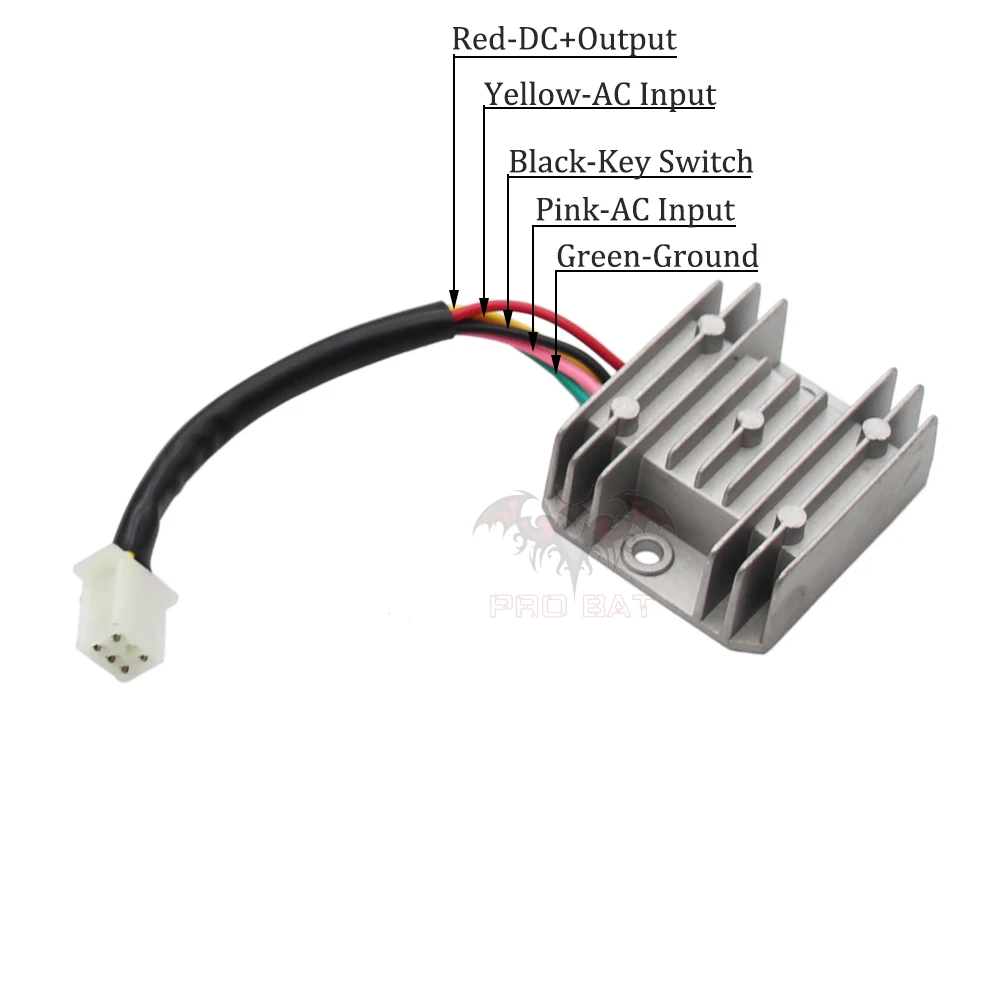
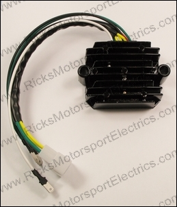
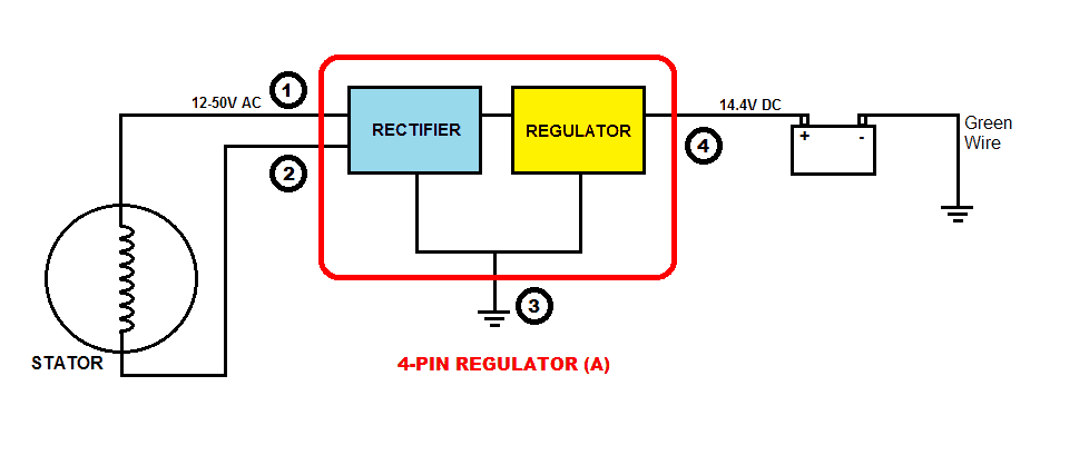
5 wire regulator rectifier wiring diagram. 4 Pin Regulator Rectifier Wiring Diagram - easywiring 4 Pin Regulator Rectifier Wiring Diagram. Many rick s motorsport electrics rectifier regulators eliminate what is commonly referred to as a signal wire on oe pieces. Simply plug the connector onto the 5 pins row and make sure that the pin assignments and wire assignments are matched correctly. Fresh Proform Alternator Wiring Diagram Diagrams ... 5pin Regulator rectifier wiring diagram(paano malalaman kung ok pa or ... 5 pin regulator rectifiier wiring diagramSana makatulong po ito sainyo mga bro.Para sa iba pang vidio wag nyo pong kalimutan magSUBSCRIBELIKE AND SHARETO GOD... Motorcycle wiring, Voltage regulator, Electrical circuit diagram Motorcycle Regulator Diagram and Amazon: Wires V Voltage Regulator Rectifier - 18+ Motorcycle Regulator Diagram - Wiringg.net ... Recitifer Regulator Signal Wires - Rick's Motorsport Electrics Recitifer Regulator Signal Wires. Many Rick's Motorsport Electrics Rectifier/Regulators eliminate what is commonly referred to as a "signal wire" on OE pieces. For example, on a 1981 Kawasaki KZ440, there are 5 wires going to the OE part: 2 yellow wires (AC inputs), white/red (DC "+" output), black/yellow (DC "-" output), and a ...
What's the point of the black wire on a 5-wire full wave ... 5 Mar 2021 — Why would you need the regulator-rectifier to *also* be on the same ... The other four-wire regulators I've seen have two wires for AC input ... 4 wires to 5 wires Regulator rectifier Paano ang connection (wiring ... Paano ang connection pag nag convert ka ng 4 wires regulator rectifier sa sa 5 wires regulator rectifier. Sana makatulong sa inyo ang simpleng video na ito.... 5 Pin Regulator Rectifier Wiring Diagram 5 pin regulator rectifier wiring diagram august 15, 2021. 5 pin rectifier wiring diagram wiring diagram is a simplified agreeable pictorial representation of an electrical circuit it shows the components of the circuit as simplified shapes and the. 6 Pin Regulator Rectifier Wiring Diagram Three Phase . M 3 2 2 2 phase 5 wire. 4 wire / 5 wire regulator rectifier wiring diagram and Explain ... All about motorcycleJHAY'D MECHANIC
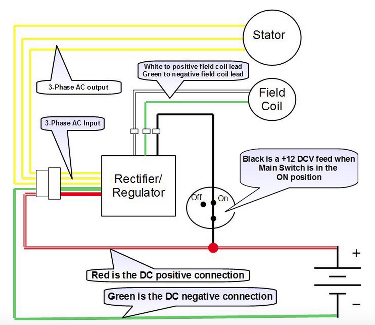
5 Wire Regulator Rectifier Wiring Diagram - easywiring 5 wire regulator rectifier wiring diagram. May 11 2018 wiring diagram. Wiring diagram for voltage regulator. 2 yellow wires ac inputs white red dc output black yellow dc output and a brown wire. How to wire the 5 cables not in a row. The yellows all come from the alternator you can connect these in any order to each other the red wire from the ... How to wire a 4 wire voltage regulator rectifier - YouTube Chinese voltage regulator wired up to honda gx clone with charge coils. 6 Wire Regulator Rectifier Wiring Diagram 6 Wire Regulator Rectifier Wiring Diagram- One of the most difficult automotive repair tasks that a mechanic or repair shop can take is the wiring, or rewiring of a car's electrical system.The suffering in reality is that every car is different. similar to frustrating to remove, replace or repair the wiring in an automobile, having an accurate and detailed 6 wire regulator rectifier wiring ... PMA swap, 5 wire and 7 wire regulator/rectifier differences 7 Mar 2016 — The 7-wire rec/reg is likely for the original energized rotor type alternator. 2 of its wires control power to the rotor, which regulates output ...
Stator - 4 wire vs 5 wire compatability | X-H2o
PDF Regulator/Rectifier Wiring Guide Reg/Rec Wiring Using Relay Circuit REG/REC WIRING FOR STANDARD 12V CHARGING: REGULATOR/RECTIFIER WIRING GUIDE 010-ELV-116 Tech Support: (844) 378-8143 technicalservice@apexproductgroup.com REG/ REC +-BA TTE LIGHT RY LIGHT RED SWITCH YELLOW YELLOW STATOR BLACK RED/YELLOW ADJUSTING REG/REC VOLTAGE DIAL: 1. Remove blue paint from adjustment dial marked "Voltage" (Fig. 2.) 2.

How to wire a 4 wire voltage regulator rectifier
Polaris Voltage Rectifier Regulator Wiring Diagram panel where the rectifier are open, causing high "ripple" or A/C voltage (while charging volts and amps are still. I replaced the voltage regulator (aftermarket, not Polaris), and I thou Polaris had a 3-wire regulator-rectifier that was used on sleds with electric start. Studying the wiring diagram a bit more, I can see that elec start sleds.

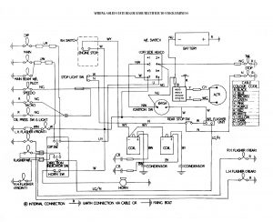
50cc Scooter Wiring Diagram Chinese Atv Cdi Wiring Diagram ...
5 Pin Rectifier Wiring Diagram - easywiring Regulator rectifier 7003 rr150 tech support. 5 pin rectifier wiring diagram wiring diagram is a simplified agreeable pictorial representation of an electrical circuit it shows the components of the circuit as simplified shapes and the faculty and signal contacts amongst the devices.

Voltage Regulator 5 Wires 12V Rectifier Motorcycle Compatible with Dirt Bike ATV GY6 50 150cc Scooter Moped JCL NST TAOTAO
Motorcycle Regulator Rectifier Wiring Diagram - Wiring Diagram How to wire a gy6 scooter regulator rectifier and how it all works part 3 the regulator duration. The article was submitted by mr. The color code remains the same. Regulator rectifier diagram here you are at our site this is images about regulator rectifier diagram posted by maria nieto in wiring category on may 08 2019.

BDX 8 And 11 Pole Stator Installation Guide :: BuggyDepot.com ...
Rectifier Regulator Wiring Diagram - Wiring Diagram Furthermore, Wiring Diagram provides you with the time frame by which the projects are for being finished. You will be capable to understand precisely if the assignments should be accomplished, which makes it easier for you personally to effectively control your time. Suzuki Gsxr 600 Fuse Box | Wiring Diagram - Rectifier Regulator Wiring Diagram.
5 wires Voltage Regulator Rectifier for GY6 125cc 150cc 200cc ...
Lambretta 5 Pin Regulator Wiring Diagram - schematron.org rectifier/regulator go along with the other items running on the electrical system; Here is a wiring diagram of the typical 5-wire CDI system on a lot of scooters comprising pick-up input, battery +12 volts in, Gnd, and Ignition coil out pins.some common electrical setups and included the wiring diagrams.

FULL WAVE regulator schematic - Techy at day, Blogger at noon ...
Wiring Diagram: 5 Pin Rectifier Wiring Diagram. Jeff Sessions 2nd ... specification: 100% !!! size: as picture shown fitment: suitable for 50cc 70cc 90cc 110cc 125cc chinese electric start quads (only fit for 2 stroke) quantity: 1 set note: only fits 5 pins cdi,do not fits gy6 engine,which e 6 pins cdi package include: 1. quad wire harness 2. cdi 3. coil with lead 4. clter switch/remote choke 5. key switch/ 2 keys 6. ngk spark plug 7. rectifier 8. solenoid 9 ...
Aftermarket Honda Regulator Rectifier | OEM Style Honda ...
6 Pin Regulator Rectifier Wiring Diagram - Diagram Schemas Wiring Provided below is an online pdf document for lamberts bikes 3 phase 6 wire regulator rectifier wiring diagram. I also show how to. 6 wire 3 phase motorcycle regulator rectifier wiring diagram. Since the incandescent bulbs work well on ac voltage there is no rectifier section in this type of regulator.

Motorcycle 5 Wires Voltage Regulator Rectifier For Honda ...
5 Pin Regulator Rectifier Wiring Diagram - easywiring 2 phase 5 wire motorcycle regulator rectifier wiring diagram pdf. We ve even included standard wire colours where appropriate. Lamberts bikes motorcycle part wiring diagrams. Simply plug the connector onto the 5 pins row and make sure that the pin assignments and wire assignments are matched correctly. M 3 2 2 2 phase 5 wire.

12v Rectifier Regulator, 4 Wire Voltage Regulator Tractor ...

Voltage Regulator - 5 Wire / 1 Plug for GY6 150cc 200cc 250cc ...

DC Regulator Rectifier, 150 watt Full Wave with Relay | TrailTech

4-Wire Full Wave Motorcycle Regulator Rectifier 12V DC Bike Quad Scooter | eBay
Wiring Solid state Single phase Regulators | JRC Engineering ...
Aftermarket Honda Regulator Rectifier | OEM Style Honda ...
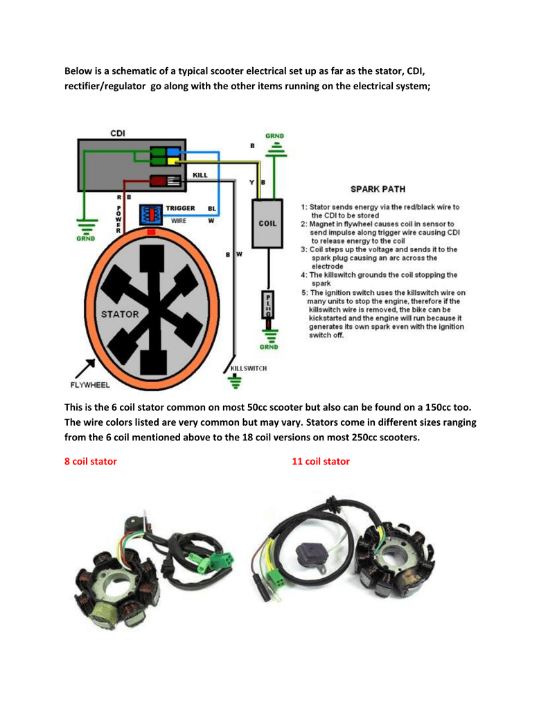
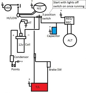
Below is a schematic of a typical scooter electrical set up ...
Regulator Rectifier 12 Volt 5 Pole AC/DC VSX VLX PX Stella
VERMON R2001.0.3 Motorcycle Rectifier High Precise Easy Operation Accessory Motor Portable Voltage Regulator Rectifier for Hondas SH 300 2007 2010 ...

Fit a Japanese Regulator Rectifier Unit to a 12v AC/DC Royal ...
Wiring new rectifier to Indiana 650. 6 wires stock, can I use ...

Perfeclan 5 wires 5 pins Voltage Regulator Rectifier for ...

Voltage Regulator - 5 Wire / 1 Plug for 250cc ATV - Version 45

Voltage Regulator / rectifier units

16+ Motorcycle Rectifier Circuit Diagram | Motorcycle wiring ...
Wiring Solid state Single phase Regulators | JRC Engineering ...
Wiring Solid state Single phase Regulators | JRC Engineering ...
Understanding Motorcycle Voltage Regulator Wiring - Homemade ...

Voltage Regulator - 5 Wire / 1 Plug for 250cc ATV - Version 45

5 WIRES VOLTAGE REGULATOR RECTIFIER FOR ATV MOPED QUAD GO KART | eBay

RECTIFIER REGULATOR 5-PIN/ DIFFERENCE COLORS - YouTube

Buy Tuzliufi Voltage Regulator Rectifier for Outboard 5 Wires ...

Mercury Mariner Outboard Force Voltage Regulator Rectifier 5 Wire 194-5279

Buy Regulator Rectifier for Mercury Mariner Outboard 5 Wire ...
Voltage Regulator 5 WIRE for GY6 125/150cc Engines: ModCycles
5 Pin 5 Wire HK-D Rectifier (Voltage Regulator) with Female Connector for 125cc-250cc GY6/QMB139 Scooter Engines
Price history & Review on 5 Wires 12V Voltage Regulator ...
Voltage Rectifier/Regulator upgrade (Honda, Yamaha rectifiers ...
Price history & Review on GY6 50 150cc Scooter Voltage ...
Regulator Rectifier for Mercury Outboards 5 Wire - 883071- JSP
Below is a schematic of a typical scooter electrical set up ...
0 Response to "40 5 wire regulator rectifier wiring diagram"
Post a Comment