42 pertronix ignitor wiring diagram
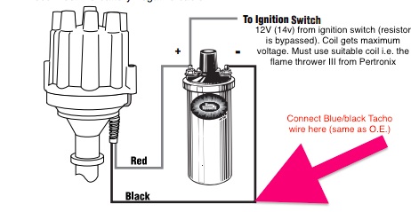
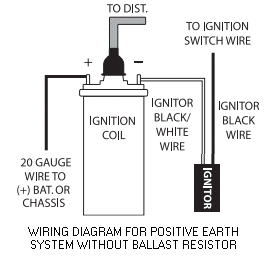
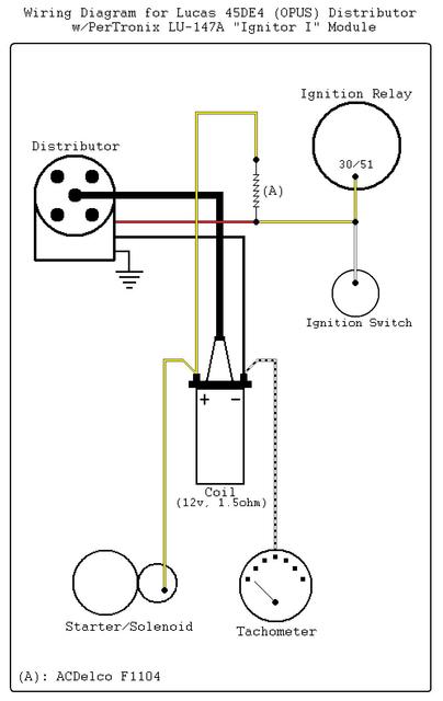
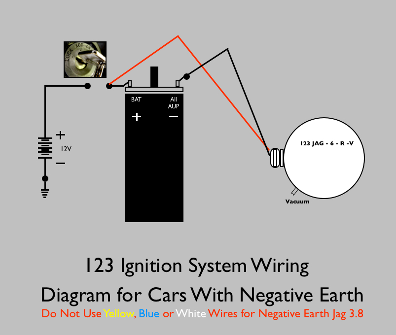
73 240z Pertronix Ignition Wiring Diagram 73 240z Pertronix Ignition Wiring Diagram First was to add the PerTronix Ignition Kit including electronic points and a new coil, So I traced the Tach wiring on the wiring diagram, and to my surprise, the. PERTRONIX IGNITOR DATSUN Z 6 CYL PERTRONIX 15 in Stock $ Quantity. Pertronix Negative Ground Wiring - ttalk.info Pertronix Igniter Wiring. For Negative Ground Cars. The wiring diagram shown below is modeled after one obtained from Pertronix. This shows the proper hookup for a Pertronix Igniter in a car wired for negative ground, or earth if you prefer. It goes without saying that this is valid only for cars without ballast resistors, viz., our T-series cars.
Pertronix Positive Ground Wiring - Pertronix Ignitor ... As stated earlier, the lines at a Pertronix Ignitor Wiring Diagram represents wires. At times, the wires will cross. However, it doesn't mean link between the wires. Injunction of 2 wires is generally indicated by black dot at the junction of two lines. There will be main lines that are represented by L1, L2, L3, and so on.
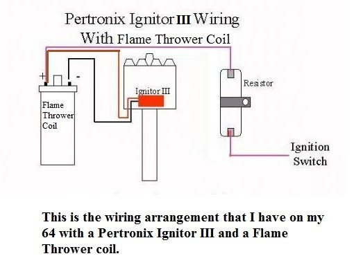
Pertronix ignitor wiring diagram
Pertronix Ignitor Wiring Diagram - schematron.org Dec 12, · Below is attached a photo of the diagram, the instructions say "the black/white ignitor wire and the 20AWG ground wire should be the only wires connected to the coil" I am a bit wiring challenged, a bit of enlightenment would be appreciated.Troubleshooting for Pertronix Ignitor and Coil InstallationPertronix Positive Ground Wiring PerTronix Electronic Ignition Systems | The Aftermarket's ... PerTronix is renowned for our Ignitor Series Electronic Conversion Kits, HEI Performance Modules, Flame-Thrower Billet, Cast, and HEI Distributors, Ignition Coils and Spark Plug Wire Sets. Ignitor Series sales have exceeded 5,000,000 units! Our innovative Digital HP Ignition Box represents our continued commitment to lead the ignition industry. PerTronix ignition … Pertronix Installation Secrets : How-To Library : The MG ... Read and follow the wiring diagram. Check it 3 times from different directions before turning the key on. Work your way from the key to the distributor, then from the distirbutor to the key. Take a break, come back, match the diagram to the car once again before you start it for safe measure, as its $80 in the trash if you miss one step.
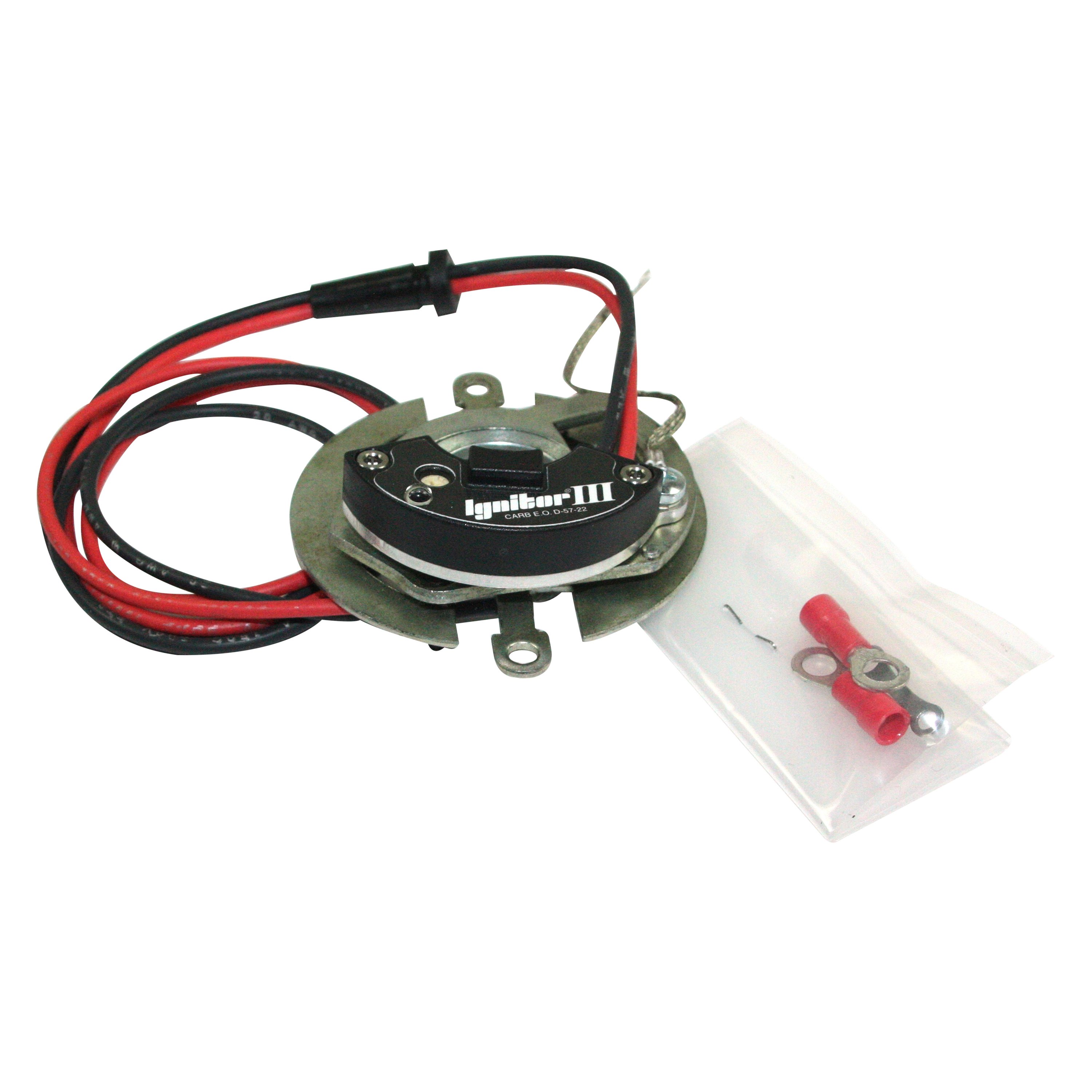
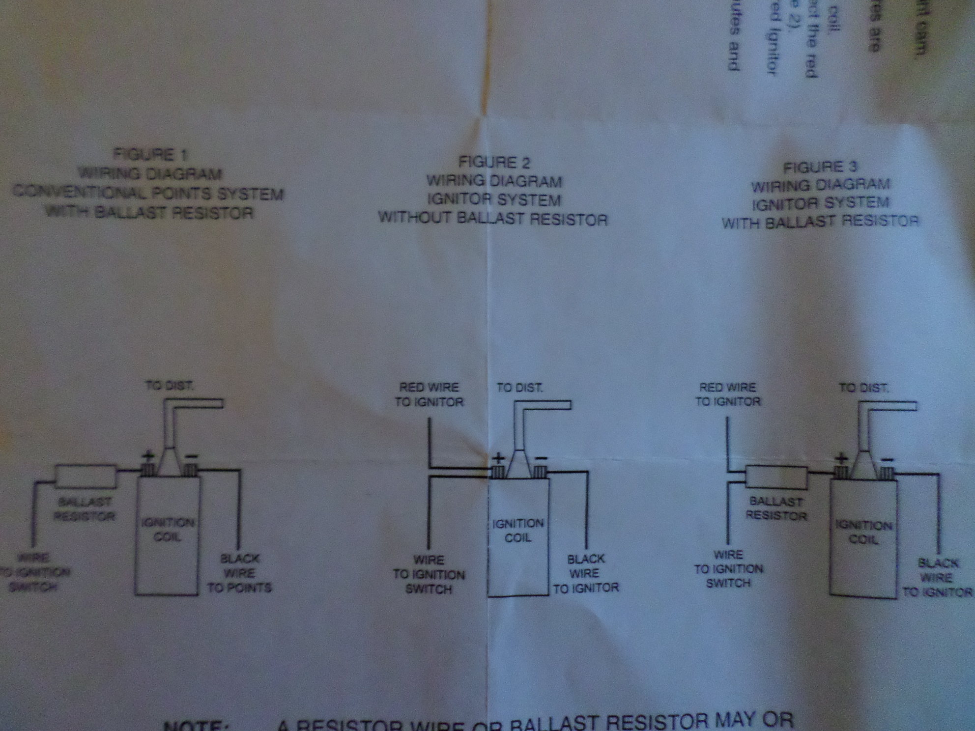
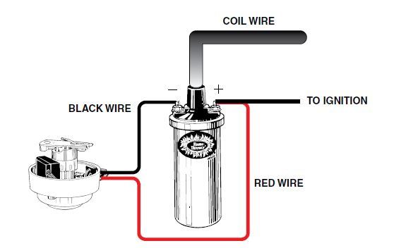
Pertronix ignitor wiring diagram. Pertronix Installation Secrets : How-To Library : The ... Do you mean a nominal 1.5 Ohm coil with a ballasted wiring loom, or a 3.0 Ohm coil (for any year wiring loom) with or without a ballast wire in the loom, or an external (e.g. ceramic) resistor? The Pertronix Ignitor needs 12V to its red wire, and a ground to its black wire. UK/USA pre 1975/76 MGBs came stock with a 3 Ohm coi PDF Installation Instructions for 12 Volt Negative Ground ... 12. Connect the Ignitor black wire to the negative (-) side of the ignition coil. 13. Connect the Ignitor red wire to the positive (+) side of the ignition coil. 14. Reconnect the battery and make sure all wires are connected correctly. 15. The engine can now be started. Let the engine run for a few minutes and Pertronix Fiat X19 Electronic Ignition Wiring Diagram The Pertronix Ignitor ® is a solid-state electronic ignition system that replaces your points and condenser, fitting completely within the distributor housing, under the cap. With no 'external black box' to clutter your engine compartment or compromise your 'stock-look' classic, the Ignitor ® allows you to "Hide some horses under your cap!". PDF 12-Volt Negative Ground Installation Instructions - CARiD.com block. Bypass this wire with a 12-gauge copper stranded wire. 1. Attach the black Ignitor wire to the negative coil terminal. (See Figure A) 2. Attach the red Ignitor wire to the positive coil terminal. (See Figure A) 3. Check to insure that the polarity is correct, and that all connections are tight. 4. Re-connect the battery. 5.
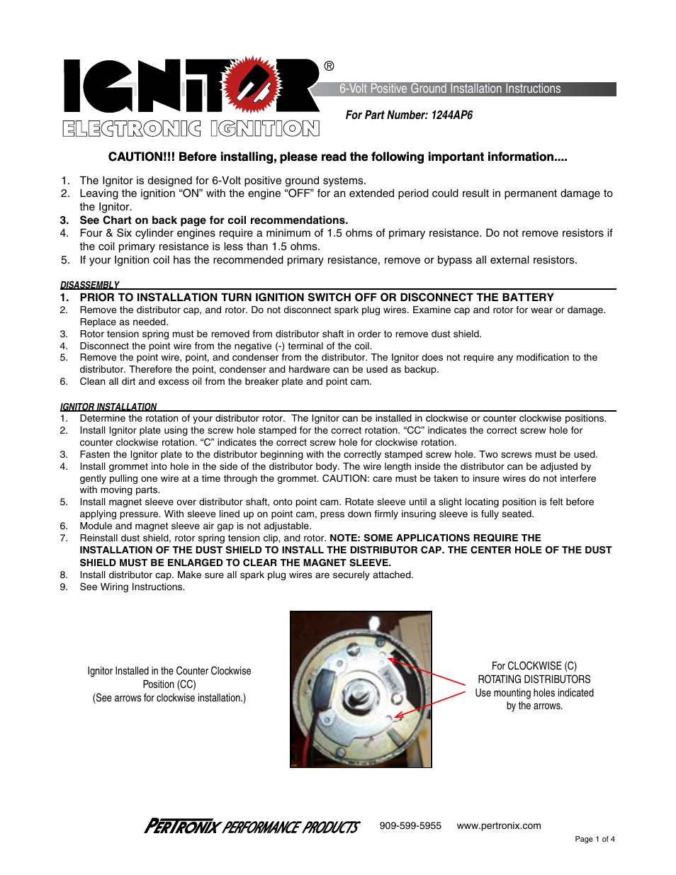
PDF Installation Instructions for 6 Volt Positive Ground ... Connect the Ignitor black/white wire to negative (-) side of the ignition coil. 14. Connect an insulated, AWG 20 copper stranded wire from the positive coil terminal to the positive battery or chassis. 15. The black/white Ignitor wire and the AWG 20 copper wire should be the only wires connected to the coil. 16. Pertronix Fiat X19 Electronic Ignition Wiring Diagram Ttalk Tech. Pertronix Igniter Wiring For Positive Ground Cars. The wiring diagram shown below was obtained from Pertronix to show the proper hookup for a Pertronix Igniter in a car wired for positive ground, or earth if you prefer. Jan 04, · Kieth, The simplest option is to use an electronic ignition setup from a Fiat Uno with the engine. How To Install a Pertronix Ignitor Ignition System Classic ... Cam and Jeff give tips and tricks on Pertronix 1 2 and 3. We show how to install the Pertonix Ignitor I Pertonix Ignitor II and Pertronix Ignitor III.http://... PDF PerTronix Performance Ignition Systems Installation ... WIRING INSTRUCTIONS 1. The Ignitor II ignition can be used in conjunction with most ignition coils rated at 0.45 ohms or greater. For optimum performance purchase and install the Flamethrower II high performance coil. 2. Attach the black Ignitor II wire to the negative coil terminal. Attach the red Ignitor II wire to the positive coil terminal.
PDF INSTRUCTION SHEET - ThisOldTractor Insert the Ignitor black and red wires through the distributor housing verifying the grommet is seated properly. 7. Install the Ignitor module using the provided hardware in the same manner as a set of points. NOTE: 1281 kits use the points adjustment screw hole as a pilot for the Ignitor locating pin. Pertronix Ignitor 1244A User Manual | 4 Pages - Pertronix ... Pertronix Ignitor Wiring Diagram - pertronix ignition wiring diagram, pertronix ignitor ii wiring diagram, pertronix ignitor iii wiring diagram, Every electric structure is made up of various different parts. Each part should be placed and linked to other parts in specific way. If not, the arrangement won't work as it ought to be. wiring diagram for pertronix flamethrower distributor ... Finally finishing up the wiring on the '54 Wagon and I ran unto a snag,,,I've lost the wiring diagram,,it's a flamethrower distributor with 2 wires and in my normal way of thinking the red wire is hot,,,but there is no red wire! Anyway, I have the correct coil I just don't want to wire it incorrectly and fry it. HRP FBO Ignition Systems MOPAR Micro-Processor IGNITION ... Wiring Diagram supplied or on line in our tech section. REV Limiter starts at 0=5200 . Each click is 200 RPM Increase. 9=7000 RPM . The HRR688 Box has a superior Algorithm type rev limiter, it does not cut every other pulse which can damage the engine, or use a rheostat to drop voltage it uses a preprogrammed pattern to give the engine a smooth REV limiter that won't stress the …
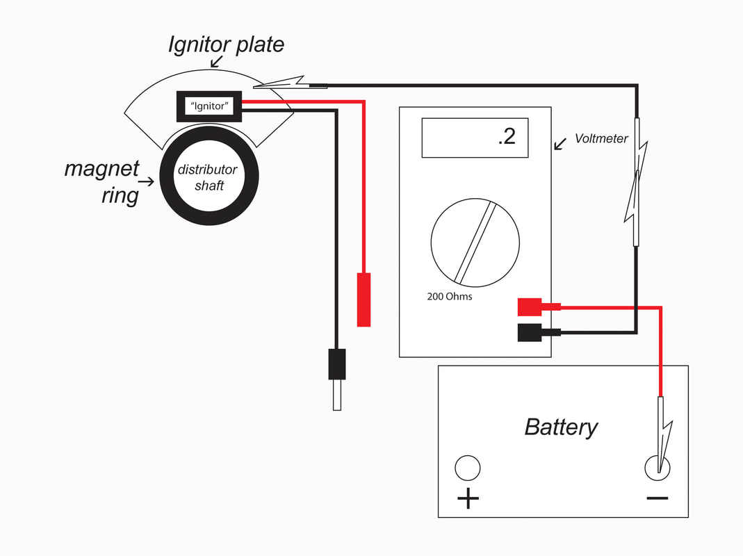
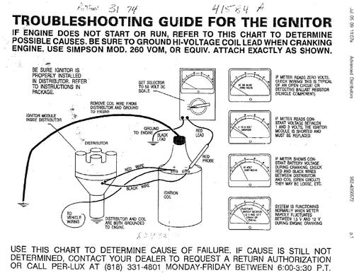
Troubleshooting for Pertronix Ignitor and Coil Installation troubleshooting tips for your pertronix ignitor ® and coil installation. note: the pertronix ignitor is effectively a "go" or "no" system. this means that if the ignitor has a fault, it will not operate at all. if the vehicle has an intermittent fault, at certain times or revs, this is generally an engine problem, and is not the fault of the ignitor.
PDF Pertronix Electronic Ignition Wiring Diagram Ford pertronix-electronic-ignition-wiring-diagram-ford 1/22 Downloaded from stats.ijm.org on April 5, 2022 by guest Pertronix Electronic Ignition Wiring Diagram Ford When somebody should go to the ebook stores, search establishment by shop, shelf by shelf, it is really problematic. This is why we provide the book compilations in this website. It will
PerTronix Electronic Distributor Ignition Systems for ... Bundles include a Flame-Thrower Billet Plug n' Play electronic distributor with Ignitor II or III electronic ignition modules, a matching low resistance Flame-Thrower chrome coil topped off with a set of 8mm MAGx2 universal wires featuring silicone jackets to resist high temperatures. Shop Now Tech Resources Ignition System Diagram
Pertronix install vs. wiring diagram | For A Bodies Only ... Look at the ignition switch diagram IGN 1 dark blue is "run" and goes to the "switch" side of the ballast, and also branches off and feeds the VR IGN 2 comes off the switch, brown, goes through the bulkhead and to the coil + side of the ballast. This is start voltage, and must be connected. Sep 8, 2014 #7
Pertronix Positive Ground Wiring - TTalk Pertronix Igniter Wiring For Positive Ground Cars The wiring diagram shown below was obtained from Pertronix to show the proper hookup for a Pertronix Igniter in a car wired for positive ground, or earth if you prefer. It goes without saying that this is valid only for cars without ballast resistors, viz., our T-series cars.
pertronix ignitor and coil wiring diagram | Vintage ... The pertronix unit needs a 12 volt power source. The coil power wire is resistor wire. You DO NOT want to apply 12 volts to your non resistor coil or it could explode. If you use the resistor wire to power the pertronix unit, it will not function properly. Mustang hobbyist building a 1969 Mustang Sportsroof. About halfway through.
Pertronix Ignition "Problems & Failures" (It's Actually ... If you don't make either of these critical errors, you will never have an issue. Spring for the ignitor 3 units only (built in miltispark, rev limiter, and w...
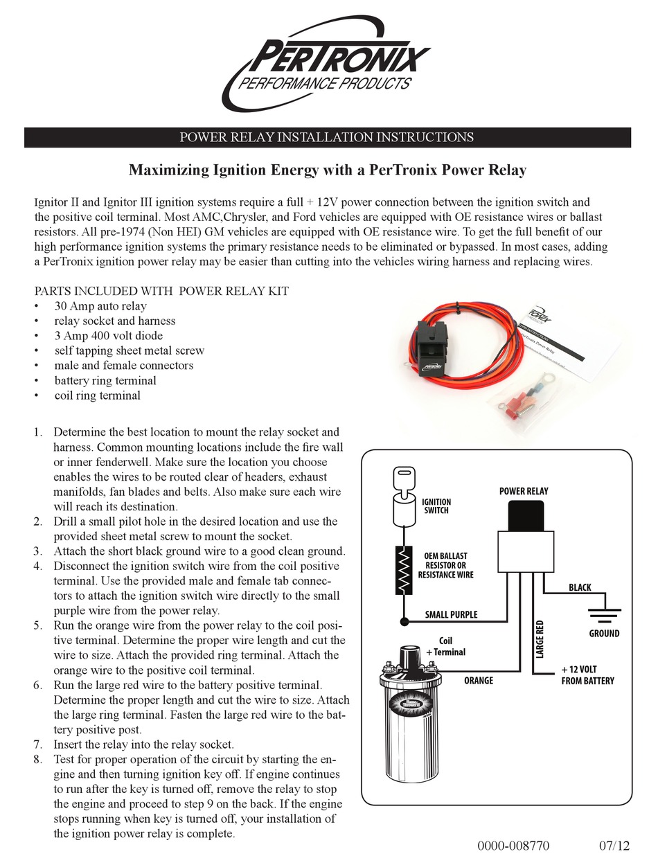
Pertronix Ignitor Wiring Diagram The wiring diagram shown below was obtained from Pertronix to show the proper hookup for a Pertronix. POWER RELAY INSTALLATION INSTRUCTIONS a PerTronix ignition power relay may be easier than cutting into the vehicles wiring harness and replacing wires. A top view of the regulator is shown in diagram below to help with terminal.
PDF 8n Ford Pertronix Ignitor Wiring Diagram 8n-ford-pertronix-ignitor-wiring-diagram 1/1 Downloaded from stats.ijm.org on April 5, 2022 by guest Thank you for reading 8n Ford Pertronix Ignitor Wiring Diagram. As you may know, people have search hundreds times for their chosen novels like this 8n Ford Pertronix Ignitor Wiring Diagram, but end up in malicious downloads.
Wiring the Pertronix wire from a Start/Run +12v circuit to the Pertronix IgnitorTMfor it to operate See schematic below. The easiest way to do this in the BOSS 302 is to use the carburetor solenoid wire. It is a Start/Run +12v source already under the hood. This is the blue wire with the white female terminal that exits at
Pertronix Wiring Diagram With Factory Tach TABLE OF CONTENTS. 1. PerTronix Technical Support () www. diagramweb.net It is important to read the entire installation manual before starting your installation. We recommend the factory spark plug heat range be used. The spark . gray wire. Determine the type of tachometer you have and follow the.
Pertronix Installation Secrets : How-To Library : The MG ... Read and follow the wiring diagram. Check it 3 times from different directions before turning the key on. Work your way from the key to the distributor, then from the distirbutor to the key. Take a break, come back, match the diagram to the car once again before you start it for safe measure, as its $80 in the trash if you miss one step.
PerTronix Electronic Ignition Systems | The Aftermarket's ... PerTronix is renowned for our Ignitor Series Electronic Conversion Kits, HEI Performance Modules, Flame-Thrower Billet, Cast, and HEI Distributors, Ignition Coils and Spark Plug Wire Sets. Ignitor Series sales have exceeded 5,000,000 units! Our innovative Digital HP Ignition Box represents our continued commitment to lead the ignition industry. PerTronix ignition …
Pertronix Ignitor Wiring Diagram - schematron.org Dec 12, · Below is attached a photo of the diagram, the instructions say "the black/white ignitor wire and the 20AWG ground wire should be the only wires connected to the coil" I am a bit wiring challenged, a bit of enlightenment would be appreciated.Troubleshooting for Pertronix Ignitor and Coil InstallationPertronix Positive Ground Wiring






0 Response to "42 pertronix ignitor wiring diagram"
Post a Comment