39 led driver wiring diagram
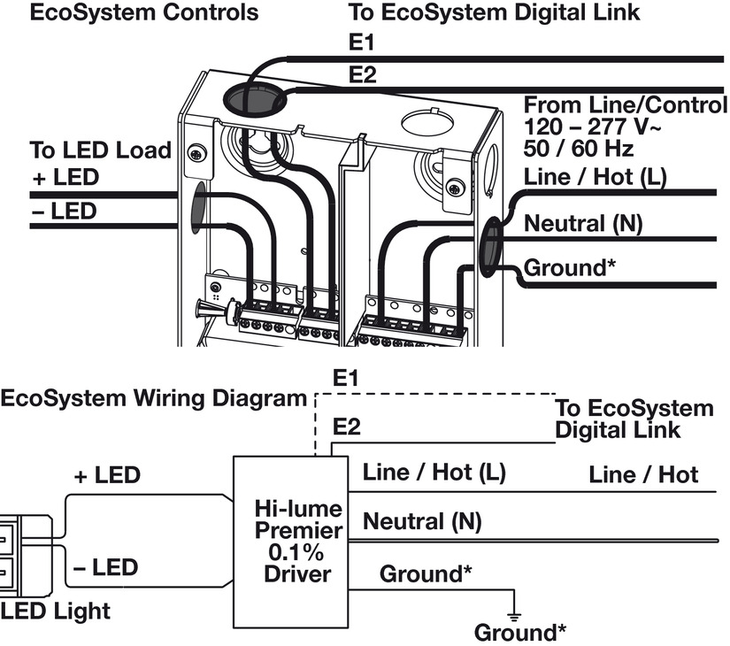
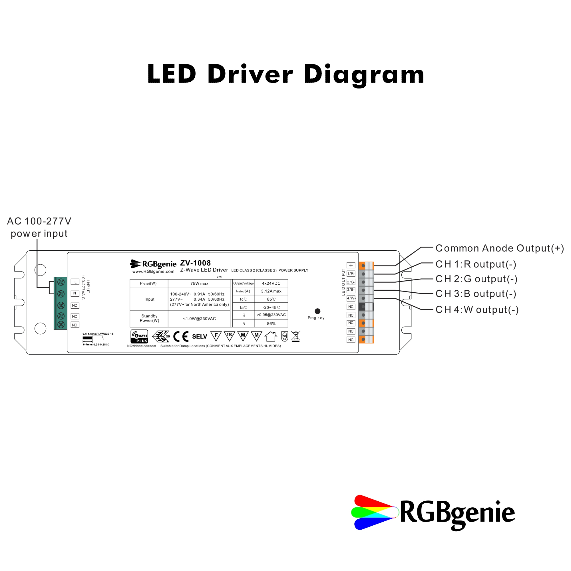
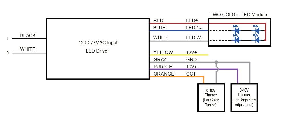
Driver terminals To EcoSystem TM Digital Link compatible devices Installing or servicing LED driver or light engine WARNING: Shock hazard. May result in serious injury or death. Disconnect power before servicing or installing. Driver Wiring For proper wiring, follow wiring schematic on driver being installed. Driver photos are for reference only. LED Dimming Driver Wiring Diagram Created Date: 7/20/2015 9:12:04 AM ...
Led Driver Circuit Diagram Pwm. Pwm led driver circuit max6948b light intensity controller homemade projects 10w white how to build a programmed power saving bright hub engineering yields 3000 1 true color dimming with any buck boost or topology from wide 3v 40v input range 亚德诺半导体 apply additional control drivers arduino a6211 ...

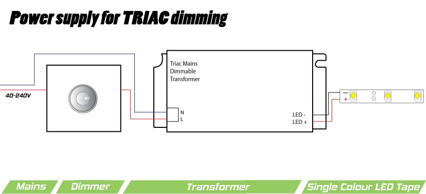
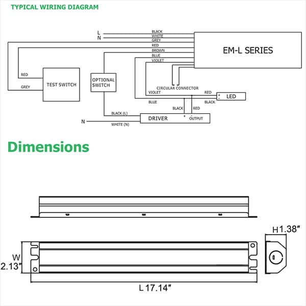
Led driver wiring diagram
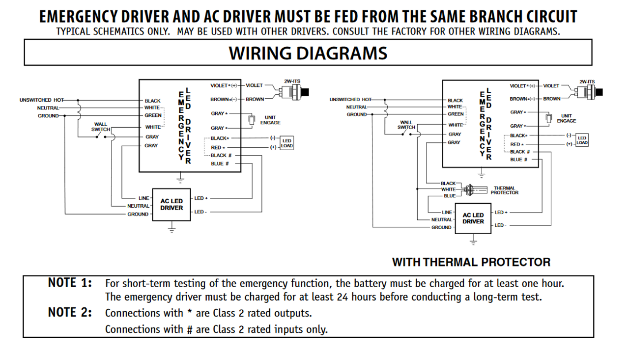
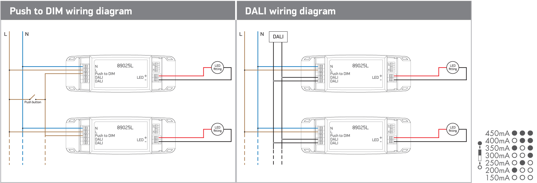
Crenshaw LED Lutron 3-wire LED dimming wiring diagram Lutron 3-wire LED dimmer switch switched hot (black ) Electrical Panel hot (black) 120V/277V ground ground dimmed hot (orange) LED pendant, sconce, or ceiling Lutron Hi-Lume A 1% L3D series Lutron 103P (120V) Lutron 103P-277 (277V) or other Lutron compatible controls switch load limits apply ... Variety of lifud led driver wiring diagram. A wiring diagram is a streamlined conventional photographic depiction of an electric circuit. It shows the parts of the circuit as streamlined shapes, and the power and also signal links between the tools. A wiring diagram generally gives details about the loved one placement and plan of devices and ... The following wiring diagrams are only applicable to Everline LED drivers that incorporate switch dimming control capabilities when connected with the Bodine BSL17C-C2 and BSL310 Emergency LED Drivers. Bi-Level switch dimming drivers have two "Hot" leads and a single neutral lead for input power connections. When either one of the switches ...
Led driver wiring diagram. Wiring Diagram Electrical Wires Cable Schematic Philips Emergency Lighting Bodine Png Clipart Angle Area. Bsl310can Spec Std L2300212. Everline Driver Application Note Emergency Led Drivers W Bi Level Switch Dimming. Installation Guide Philips Evokit Led 2x4 And 2x2. Emergency Led Drivers W Universal Lighting Technologies. Collection of lifud led driver wiring diagram. A wiring diagram is a streamlined traditional photographic depiction of an electric circuit. It shows the parts of the circuit as streamlined shapes, and the power and signal connections between the tools. Wiring LEDs in Parallel. Parallel wiring is most often used when working with constant voltage drivers. A lot of people are now using constant voltage drivers and wiring up their COBs in parallel, since the drivers are usually cheaper and people are more comfortable working with low voltages like 36V, as opposed to high-voltage series circuits that can be 200V+. Note: Driver with splice box can be pre-wired before assembly to Flat Panel. the packaging. Inspect product for defects due to shipping. 2' x 2' LED Flat Panel Shown (1) LED Flat Panel (1) Instructions (1) Driver with Splice Box Note: (3) Wire Nuts and (1) Thumb Screw included in Splice Box Tee-grid bar LED Flat Panel Grid Clips Driver ...
Mr16 Bulb Wiring Diagram. Mar 26, To make an LED-based MR16 bulb backward-compatible with 3: MR16 application diagram — LED-driver circuit in base of MR16 bulb. Electronic transformers designed for Halogen lamps will kill LEDs. Electronic transformers are very simple switched mode power supplies. Replacing the driver in your Altair Lighting LED lantern. Before starting, we need to make sure we have the right parts. Purchase the APC-16-350 here by selecting the 16 Watt, 350mA Current model. Follow the video above to disassemble the light. Disconnect the quick connector from the LEDs and cut the connector off (with some extra wire) from ... LED DRIVER HOT/LINE BLACK COMMON/NEUTRAL WHITE YELLOW WHITE BLACK Reverse phase ELV wiring diagram LINE VOLTAGE 120V 120V OUTPUT LED LOAD LOW VOLTAGE DC POWERED BY LTF ® L.T.F, L.L.C. PHONE: (847) 498-5832 FAX: (773) 337-5628 EMAIL: sales@ltftechnology.com Company's Address: 11966 Oak Creek Pkwy. LED PWXL D + TRL - TRL + D - A IN 4-6W LED Driver LED 010VD Dimming control PWXLD INSTALLATION NOTES: 1. Turn off power to the circuit prior installing. ONNETING TO LIVE POWER MAY AUSE PERMANENT DAMAGE TO THE DRIVER. 2. Use wire nuts on all connections and cap any unused wires. 3. LED string (D +/-) should be con-nected first, and must be connected
and simple programming, the drivers make it easy for luminaire manufacturers to design luminaires of different sizes and lumen levels for outdoor applications. LED Driver Xitanium Specifications Wiring Diagram 300W 347-480V 0.1-1.50A XH300C150V300BSR1 Input Voltage (Vac) Output Power (W) Output Voltage (V) Output Current (A) Efficiency@ Max ... 1. LED Driver Distance Guide 2. Wiring Diagram 3. Wiring Installation Guide 4. (Optional) IP67 Driver Box and Waterproofing EQUIPMENT CHECKLIST Some of the items you will need include: - Electrical pliers - Puck pliers (provided) - Wire hook (provided) - Cable Snake LED PUCK WIRING GUIDE Scan to view or download these instructions online Led Driver Wiring Diagram Sample. led driver wiring diagram - A Newbie s Overview of Circuit Diagrams A first look at a circuit diagram may be complicated, but if you can check out a subway map, you can check out schematics. The purpose is the exact same: obtaining from factor A to aim B. Literally,… EMERGENCY LED DRIVER EMJ-0825-010/105-J2 WIRING DIAGRAMS Wire Length (inches) N(White) 29.5 L(Black) 29.5 SW(White/Black) 29.5 Test+(Purple ... H 55.5mm W 55mm L1 256mm L2 251mm WIRING DIAGRAM (TYP) WIRING DIAGRAM (EMERGENCY ONLY) EMERGENCY LED DRIVER EMJ-0825-010/105-J2 BATTERY CHART Batter Type Model name Battery Type Capacity Wattage Battery ...
Attaching Wires to RGB Flexible LED Strip Solder Connection Step #2: If using our control cable, strip the casing approximately 3/4". Strip each small wire 1/8". For added protection, put a 1" long piece of heat shrink tubing over the wire (So that when you are finished you can position it over the connection).
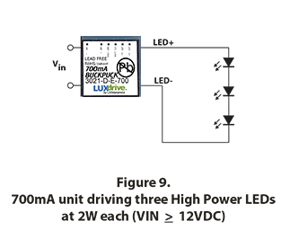
The image to the right shows an example: To wire a series circuit like the one shown, the positive output from the driver connects to the positive of the first LED and from that LED a connection is made from the negative to the positive of the second LED and so on, until the last LED in the circuit.
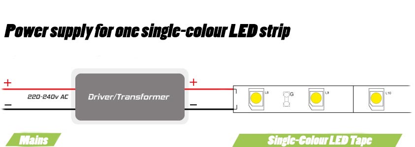
230v LED Driver Circuit Principle. The basic principle behind the 230V LED Driver circuit is transformer less power supply. The main component is the X-rated AC capacitor, which can reduce the supply current to a suitable amount.
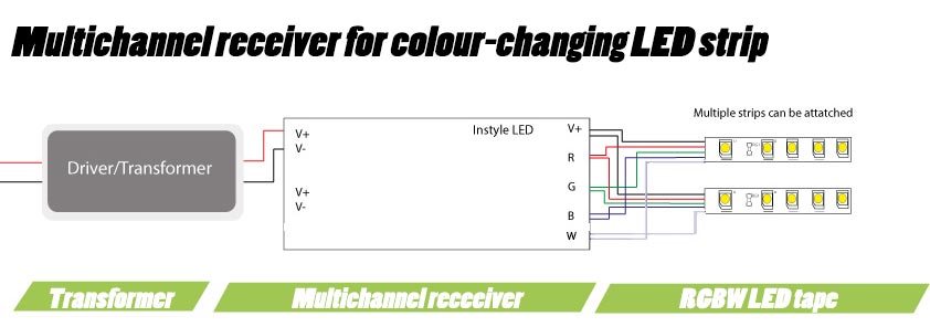
Dimensions and Schematic Diagram 6. Ensure that the LED RGB strip load does not exceed that of the driver, the driver supplied can power a maximum continuous run of LED RGB strip lights of 5 Metres. 7. Switch on the power supply for testing and adjustment. 8. Over the tailing end of the LED strip light fit an End Cap
OTi30 Linear Driver LED Thermal Protection Output Current OTi30 Linear Driver LED Thermal Protection Wiring Diagram OTi30W Wiring Diagram for AUX Models OTi30W Wiring Diagram for nonAUX Models Electrical specifications - Auxiliary output (for AUX models only) Output Current (mA) Aux Only 40 Output Voltage (VDC) Aux Only 12/20/24V (configurable)
You can connect one, two or three 1w 350mA LED products to our 1-3w 350mA Constant Current LED Driver (1275). If you are wiring more than one product, the products must be wired in series, not parallel. Single 1w 350mA LED product connected to a 1-3w 350mA LED Driver 1-3w 350mA Constant Current
LED Driver Xitanium Specifications Wiring Diagram 95W 0.1-2.75A 0-10V Dimming with SimpleSet XH095C275V054BSF1 Enclosure Input Voltage (Vac) Output Power (W) Output Voltage (V) Output Current (A) ... Philips Advance Xitanium LED Drivers are manufactured to engineering standards correlating to a designed and average life expectancy of 50,000 ...
PHOTO CONTROL WIRING DIAGRAM 208V, 240V, 277V, 480V BLK RED LINE LINE PHOTO CONTROL WHT LAMPLOAD RED OR WHT BLK BLK YEL COMPACT FLUORESCENT BALLAST WIRING DIAGRAMS 1 - 1 LAMP 2 - 2 LAMP Quad-volt ballasts are factory-wired for 277V input. Before installation make certain supply and ballast voltages are compatible.
A typical V wiring diagram is shown below: V Dimming. DIML2: Our standard V dimming driver option is often provided standard (check spec sheets) and dims down to 10% at minimum light level. V Class 1 and Class 2 Wiring Overview V ballasts and drivers are connected together by a 2-wire low voltage bus that is suitable for Class 1 or Class 2 ...
1) power dissipation. Q2 acts as a variable resistor, stepping down the voltage from the power supply to match the need of the LED's. so Q2 will need a heatsink if there is a high LED current or if the power source voltage is a lot higher than the LED string voltage. (Q2 power = dropped volts * LED current).
Thank you for All wiring and installation of the light fitting must adhere to local and national wiring rules. eg. AS/NZS The LED driver is rated IP20 and the LED downlight is rated IP This must be.Jun 22, · what size cable for downlights, cable for led downlights, cable size for v downlights, cable for downlights, wiring downlights, flex size ...
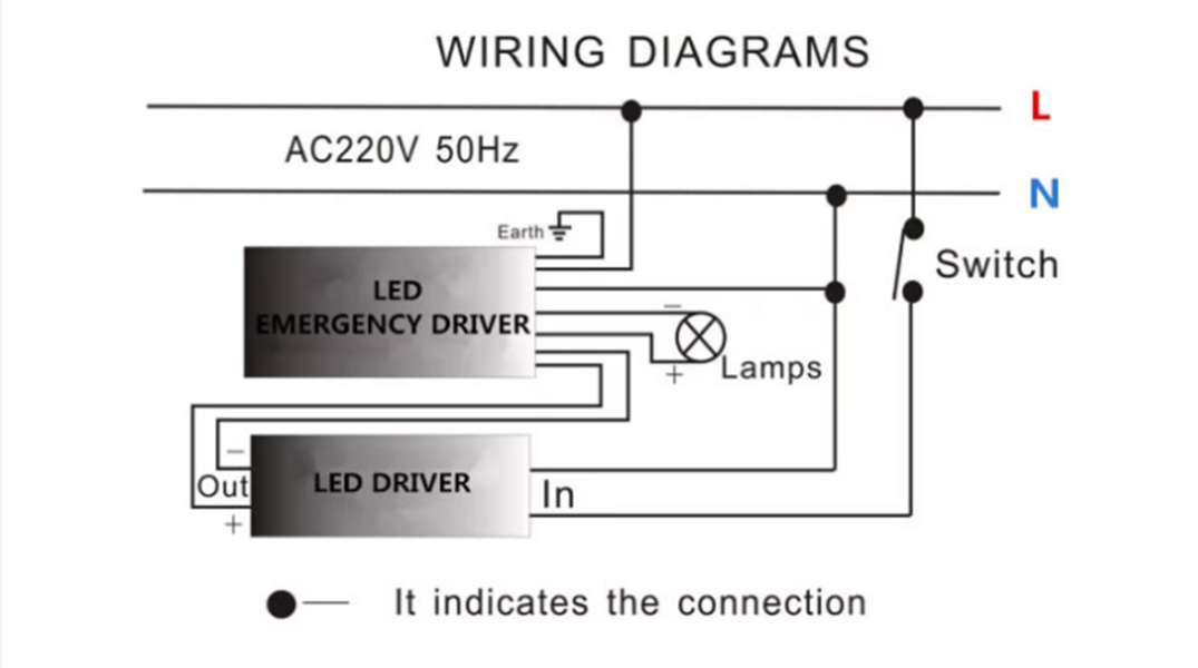
The following wiring diagrams are only applicable to Everline LED drivers that incorporate switch dimming control capabilities when connected with the Bodine BSL17C-C2 and BSL310 Emergency LED Drivers. Bi-Level switch dimming drivers have two "Hot" leads and a single neutral lead for input power connections. When either one of the switches ...
Variety of lifud led driver wiring diagram. A wiring diagram is a streamlined conventional photographic depiction of an electric circuit. It shows the parts of the circuit as streamlined shapes, and the power and also signal links between the tools. A wiring diagram generally gives details about the loved one placement and plan of devices and ...
Crenshaw LED Lutron 3-wire LED dimming wiring diagram Lutron 3-wire LED dimmer switch switched hot (black ) Electrical Panel hot (black) 120V/277V ground ground dimmed hot (orange) LED pendant, sconce, or ceiling Lutron Hi-Lume A 1% L3D series Lutron 103P (120V) Lutron 103P-277 (277V) or other Lutron compatible controls switch load limits apply ...













0 Response to "39 led driver wiring diagram"
Post a Comment