41 hydraulic brake system diagram
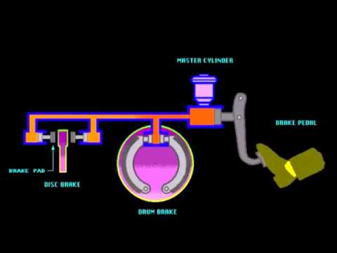
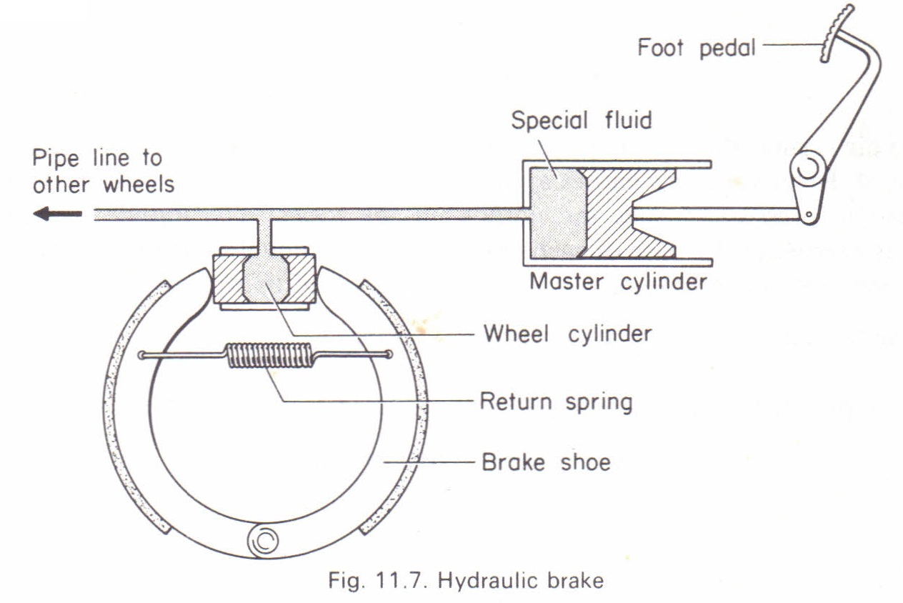
Taking one wheel's hydraulic brake circuit as an exam- ple, a schematic diagram of a hydraulic braking system is shown in Figure 1. Hydraulic disc Braking System Diagram Working of Hydraulic Disc Brake : In a disc brake, the fluid from the master cylinder is forced into a caliper where it presses against a piston. The piston in turn crushes two brake pads against the disc that is being attached to the wheel, making it to stop or slow down.
brake rotor and caliper. The wheel hub and brake assembly components should be thoroughly wetted to suppress dust before the brake shoes or brake pads are remov Wiped. e the brake parts clean with a cloth. c. If an enclosed vacuum system or brake washing equipment is not availabl e, employers may
Hydraulic brake system diagram
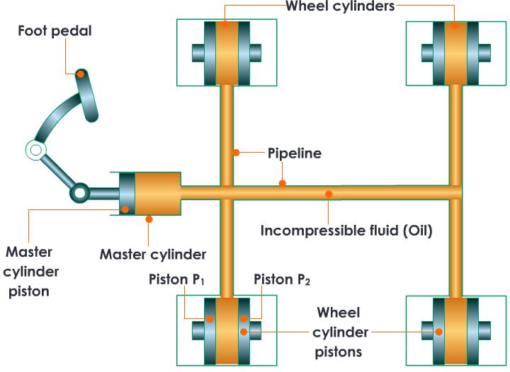
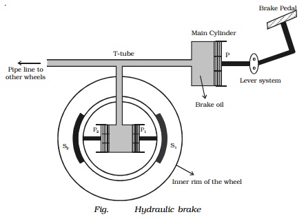
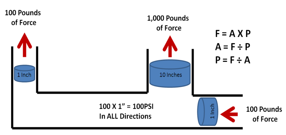
Hydraulic Braking system working principle: The hydraulic braking system works on the principle of Pascal’s Law. PASCAL’S LAW:- The pascal law states that a “Pressure at any point in a static fluid is equal in all directions”.. Hence such pascal’s law is used in the hydraulic braking system to apply the brake. a hydraulic disc brake. The amount of lever actuation combined with the leverage of the brake lever and hydraulic system create a clamping force at the caliper. That clamping force combined with the brake pad material produces friction at the rotor. The amount of friction combined with the diameter of the rotor generates braking power. Braking Figure 27 Simple Hydraulic Power System. Figure 28 Line Diagram of Simple Hydraulic Power System. With an understanding of the principles involved in reading fluid power diagram, any diagram can be interpreted. Figure 29 shows the kind of diagram that is likely to be encountered in the engineering field.
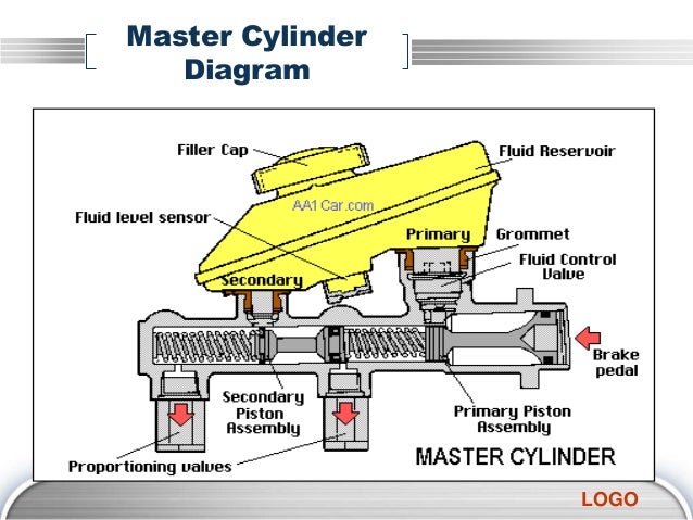
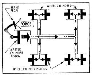
Hydraulic brake system diagram. 25 Sep 2019 — The major components in the hydraulic brake system circuit are connected fluid-filled master cylinder and slave cylinders. When the driver ... A hydraulic braking system is a brake pedal attached to a piston full of a nearly incompressible brake fluid connected to another piston near the wheels attached to brake pads which push on the rotors on a wheel. When you push down on the brake pedal of a car, you make some fluid pressure P=Force/Area where the force is the force of your foot ... This diagram shows a typical street rod brake system. A 2 PSI residual pressure valve (RPV) is needed in the disc brake circuit, and a 10 PSI RPV is required in the drum brake circuit as well as an adjustable proportioning valve (APV). This diagram illustrates the 2 most common types of fittings used in street rod brake systems. System operation — A schematic illustrating the major components of a hydraulic disc brake system. A hydraulic brake is an arrangement of braking mechanism ...
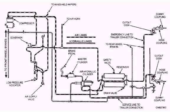
equipped with hydraulic brakes, built after August 21, 2006 feature the Meritor WABCO Full Power Brake system. The Full Power Brake system provides better pedal feel, shorter stopping distances, antilock brakes, and traction control. But the Full Power Brake system offers a lot more, like Electronic Brakeforce Distribution to compensate for axle A hydraulic brakes system is a braking mechanism that uses brake fluid to ... Hydraulic braking systems are widely used in low-speed four-wheelers such as ...What Is Hydraulic Braking System?Construction of Hydraulic Braking System: steps on the brake pedal. If the system is equipped with the optional power park brake, the HCU also supplies the energy to release and control the service and park brakes. The Meritor WABCO HPB system for trucks is illustrated in Figure 1.8. A complete HPB system layout, with hydraulic brake lines, appears in the Appendix. Figure 1.8 Figure 1 ... FS Parking brake control cylinder C33 / E25 I.D. Power steering E32 M Manipulator M18 MC Brakes pump A38 MI Hydrostatic motor M34 MT I.C. engine M22 M.V. Fan motor Q16 P Pump Q4 P.A. Optional connector C11 PF Brake pedal A35 PH Hydrostatic pump M23 P.V. Pump Q9 R Hydraulic uid tank S4 Rd Oil radiator Q38 S. Brakes liquid tank C40
26 Sep 2020 — ... diagram, types, and working of the hydraulic braking system. ... The braking system uses hydraulic fluid to transmit the brake pedal or ... Figure 27 Simple Hydraulic Power System. Figure 28 Line Diagram of Simple Hydraulic Power System. With an understanding of the principles involved in reading fluid power diagram, any diagram can be interpreted. Figure 29 shows the kind of diagram that is likely to be encountered in the engineering field. a hydraulic disc brake. The amount of lever actuation combined with the leverage of the brake lever and hydraulic system create a clamping force at the caliper. That clamping force combined with the brake pad material produces friction at the rotor. The amount of friction combined with the diameter of the rotor generates braking power. Braking Hydraulic Braking system working principle: The hydraulic braking system works on the principle of Pascal’s Law. PASCAL’S LAW:- The pascal law states that a “Pressure at any point in a static fluid is equal in all directions”.. Hence such pascal’s law is used in the hydraulic braking system to apply the brake.
Jstor Org

1221 Truck Air Over Hydraulic Brake System Fig 121 Vehicle Technology

1 General Description 1 1 Dual Diagonal Braking System

Hydraulic Brakes Parts Working Diagram Advantages And Disadvantages
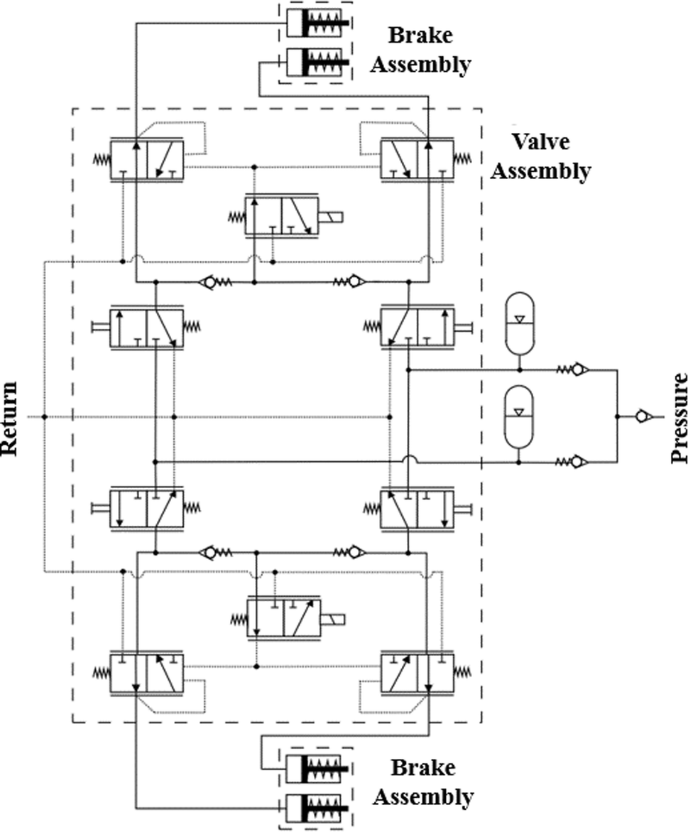
Figure 4 Use Of Lms Amesim Model And A Bond Graph Support To Predict Behavior Impacts Of Typical Failures In An Aircraft Hydraulic Brake System Springerlink

5k3663 Air Over Hydraulic Brake Power Assembly 5k3663 Caterpillar Spare Part 777parts
Hydraulic Brakes Automobilians Com All About Automobiles
Jstor Org
Applications Of Pascal S Law Hydraulic Lift And Brake

Hydraulic Brake System When The Brake Pedal Is Pressed A Push Rod Exerts Force On The

Working Of Layout Of Hydraulic Brake System Brakes And Dynamometers Theory Of Machine Youtube
1
Basic Hydraulic Brake Circuit Operation Youtube

Safe Aircraft Parking Safety First

Air Brake System Components Working Automotive Science Facebook
Diy Auto Service How Hydraulic Brake Systems Work Axleaddict
Air Over Hydraulic Brake System

What Is Hydraulic Braking System Construction Of Hydraulic Braking System Parts Of Hydraulic Braking System
Hydraulic Braking System

Brakes Hydraulic Brakes Brake Failure Abs Abs Brakes Antilock Brakes
1
Hydraulic Brake System

Schematic Diagram Of The Hydraulic Braking System Download Scientific Diagram

Hydraulic Brake System Components
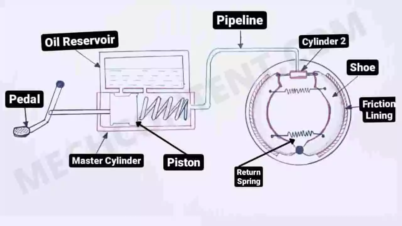
Hydraulic Braking System With Pdf Hydraulic Brake Mech Content

Braking System Ppt Download
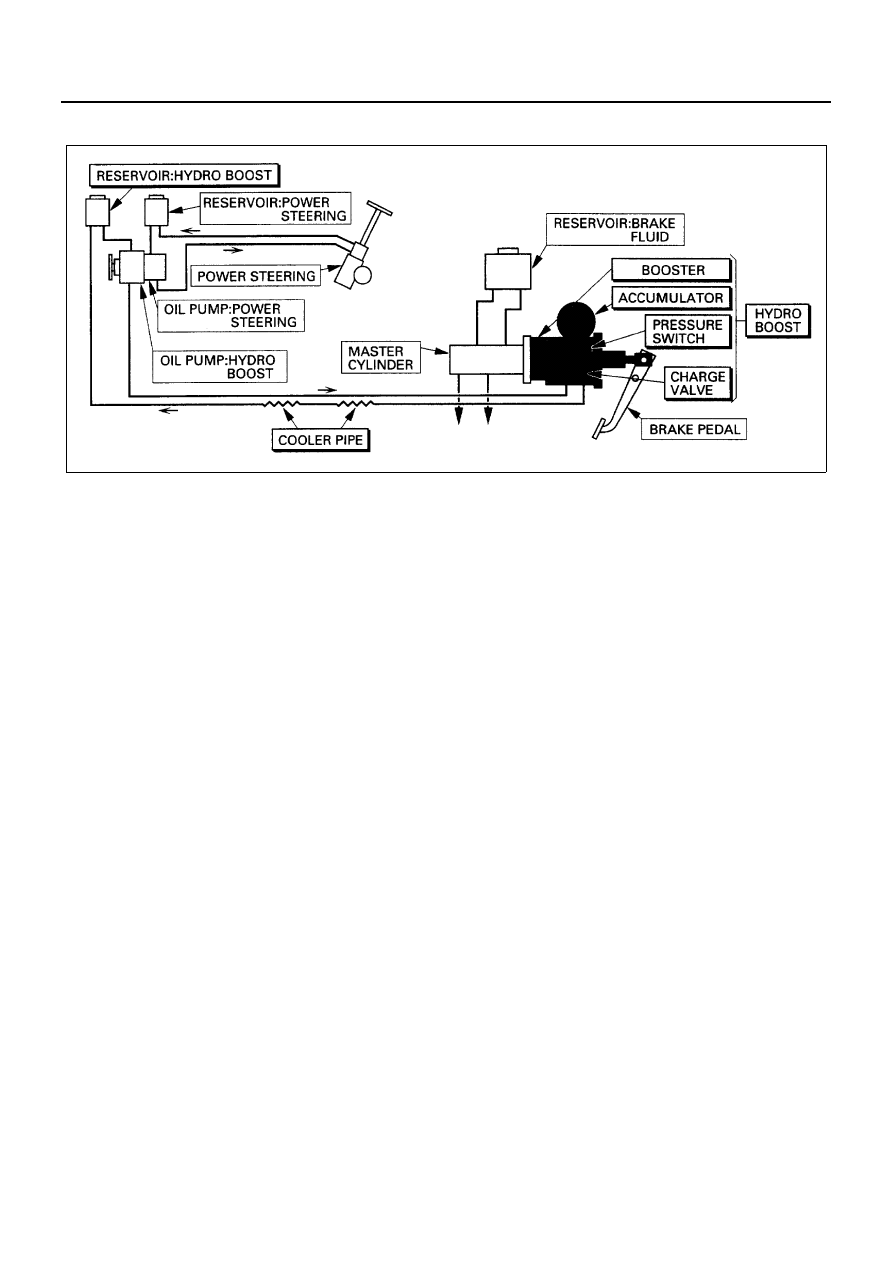
Isuzu N Series Manual Part 211
Tezu Ernet In
The Transmission Of Pressure In Fluids Hydraulic Brake Physics Homework Help Physics Assignments And Projects Help Assignments Tutors Online

Hydraulic Braking System Automobile

Hydraulic Brakes Parts Working Diagram Advantages And Disadvantages

Procedures For Inspecting Vacuum Hydraulic Brakes Fire Engineering

Schematic Diagram Of The Hydraulic Brake System Download Scientific Diagram

Hydraulic Braking System Automobile
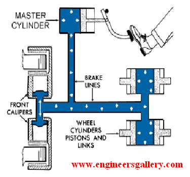
Hydraulic Brake Engineers Gallery

Hydraulic Brakes Parts Working Diagram Advantages And Disadvantages

File Hydraylic Disc Brake Diagram Jpg Wikimedia Commons

Diy Auto Service How Hydraulic Brake Systems Work Axleaddict

Schematic Diagram Of The Hydraulic Braking System Download Scientific Diagram

Pdf Design Model Of A Vacuum Assisted Hydraulic Braking System Semantic Scholar

Safe Aircraft Parking Safety First
0 Response to "41 hydraulic brake system diagram"
Post a Comment