36 truss free body diagram
The free-body diagram of the truss as a whole is used for the calculation of reactions, and another set of free-body diagrams is used for the calculation of ...
Drawing Free Body Diagrams. Free-body diagrams have been used in examples throughout this chapter. It is generally customary in a free-body diagram to represent the object by a box and to draw the force arrow from the center of the box outward in the. Page4 (Gussie Malone) Let's see what this one looks like. With the help of free body diagram ...
The free-body diagram of the truss will show that joints A and B satisfy this requirement. To determine the axial forces in members meeting at joint A, first isolate the joint from the truss and indicate the axial forces of members as FAB and FAD, as shown in Figure 5.10c.

Truss free body diagram
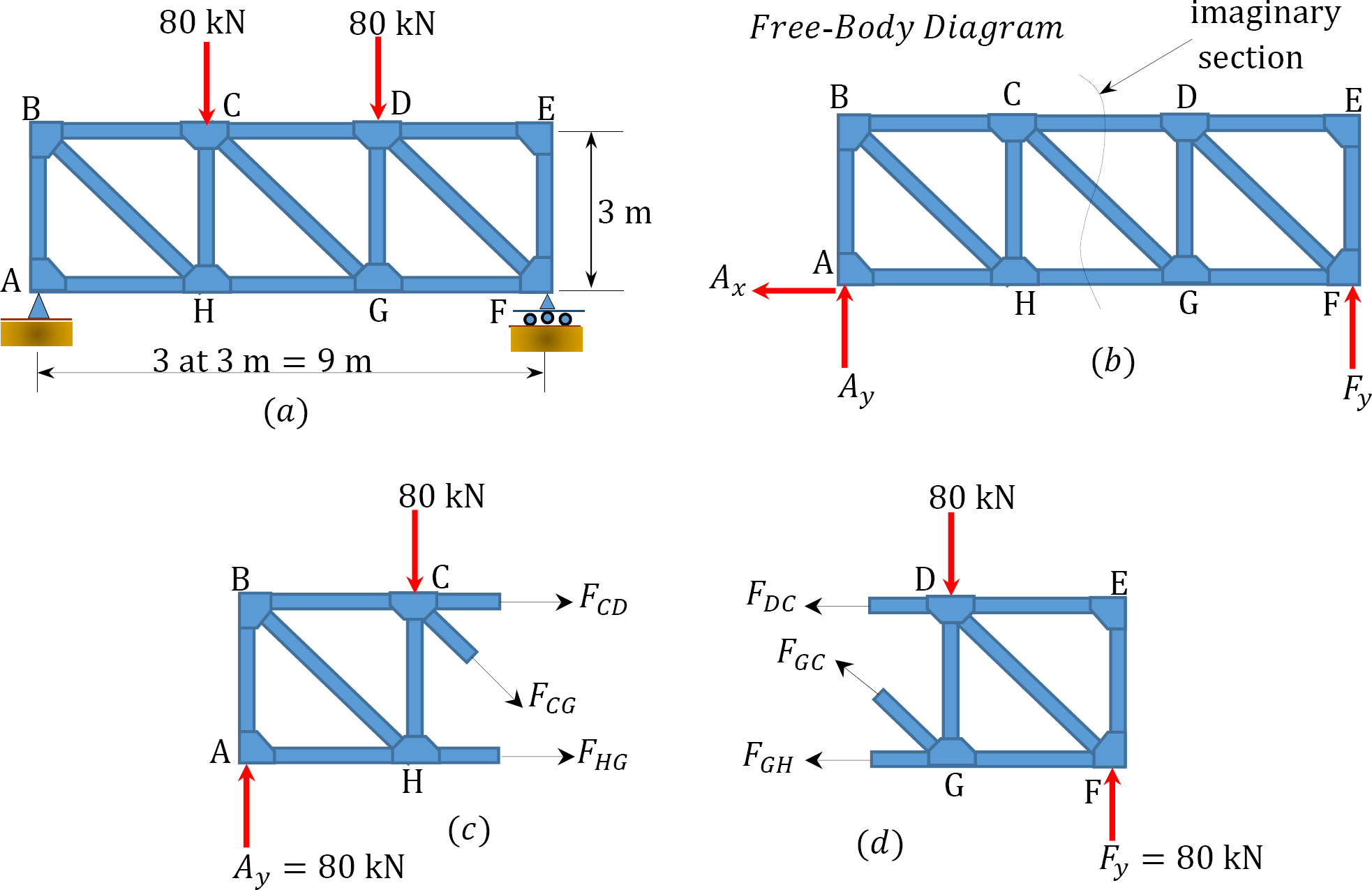
To apply the method of sections, we use an imaginary cut through members of the truss to expose the forces in those members as external forces. Figure If the free-body diagram of the joint on either side of the cut is known, we can apply the equations of equilibrium to that part of the member to determine the forces at the cut section.
Once you have the reactions, draw your Free Body Diagram and Shear Force Diagram underneath the beam. Finally calculating the moments can be done in the following steps: 2. From left to right, make "cuts" before and after each reaction/load. To calculate the bending moment of a beam, we must work in the same way we did for the Shear Force ...
The two elements at joint "C" are joined at a straight angle and the joint is not loaded externally. The free-body diagram of joint "C" (Truss Joint) shows that in order to preserve equilibrium, the force for each element must be zero. Additionally, like with joint "A" (Truss Joint), this has to be bad despite of the angle between the members.
Truss free body diagram.
A Free Body Diagram is a visual representation of force and object interactions. Individual objects or members are ... Beams and truss bridges are usually.25 pages
Draw a free body diagram. CO-3: Compute moments due to a force and moment arm and compute equivalent force/couple systems. CO-4: Solve for unknowns in a static equilibrium problem, truss, frame and machine problems, and problems involving dry static friction
Draw Free Body Diagram of Truss; Determine external reactions by applying equilibrium equations to the whole truss; Perform the force analysis of the remainder of the truss by Method of Joints; Example 1 . Determine the force in each member of the loaded truss by Method of Joints. Solution. Truss Member Carrying Zero forces
Download the DegreeTutors Guide to Shear and Moment Diagrams eBook. 📓. This is a problem. Without understanding the shear forces and bending moments developed in a structure you can't complete a design. Shear force and bending moment diagrams tell us about the underlying state of stress in the structure. So naturally they're the starting ...
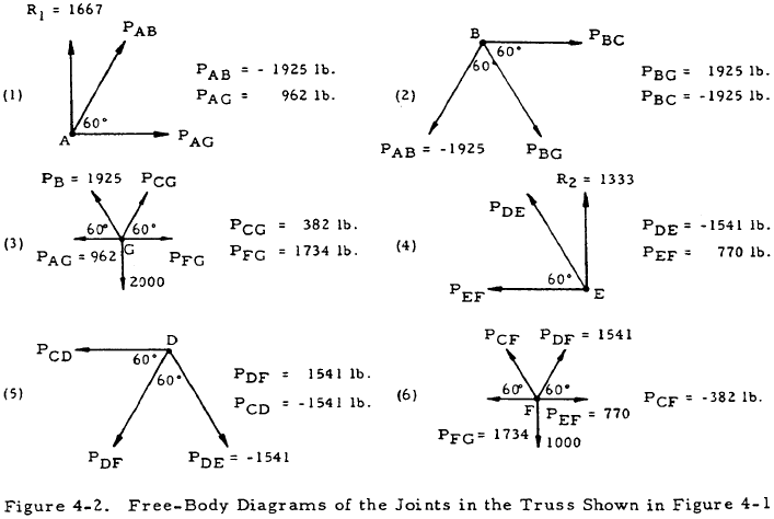
However, this truss will be analyzed completely, so the first step will be to compute the external forces at D and E from the free-body diagram of the truss as a whole. The equations of equilibrium give ∑M E =0] ∑M E = 0] we have fbd showing the forces acting on each of the connecting pins.
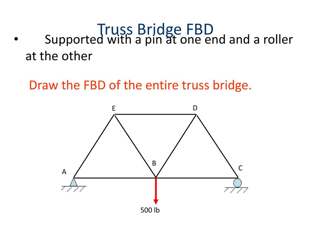
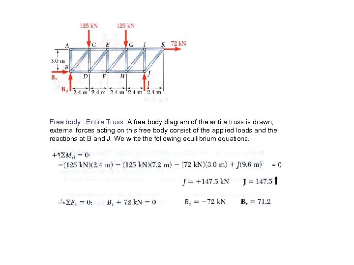
Create a Free Body Diagram of the entire truss including all external applied and reaction forces. Do not worry about individual members; treat the truss as ...3 pages
Academia.edu is a platform for academics to share research papers.
Axial Force diagram (N) Shear Force diagram (V) Bending Moment diagram (M) Drawing of the Model Deformation with automatic scaling support and s howing intermediate deformation values on screen. Drawing of the Free Body Diagram (F) picture which shows the Model, all the forces (external forces and support reactions) and the Model equilibrium.
Balok Truss . Balok yang tinggi dapat dibuat dari struktur baja komposit gabungan : Profil T, pipa dan Plat beton bertulang. (sumber : ... Free Body Diagram Truss2D. 08. Free Body Diagram Elemen Frame. Diposting oleh sumirin di 15.17 Tidak ada komentar: Kirimkan Ini lewat Email BlogThis!
Draw a Free-Body Diagram. 3. Compute moments due to a force and moment arm. 4. Compute equivalent force/couple systems. 5. Solve for unknowns in a static equilibrium problem, truss, frame and machine problems, and problems involving dry friction. 6. Locate the centroid of 2D and 3D objects. C. Course Learning Outcomes: CO-1:
The truss structure is loaded only at the joints. The weights of the members may be ... Truss – Example Problem. Draw the free-body diagram. The summation.17 pages
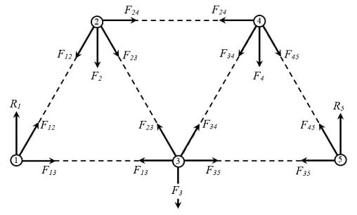
Bridge truss design drawing, with a brief description/history of the truss used; Example of a free body diagram for the analysis of forces on a truss node; System of equations resulting from the analysis of forces; this can be a snapshot of the matrix in the graphic interface; Screenshot of the specified load applied on the truss
Draw the free body diagram for the truss. a is a pin and b is a ...
Step 1: Calculate the Reactions at the Supports. We will start by looking at a simple example of a 5 member truss system: To calculate the bending moment in this truss system, we first take the sum of moments at the left reaction to be zero. We do this by ignoring all the members and just looking at the forces and supports in the structure.

Analyzing a simple truss by the method of joints : 12 steps (with ...
A simple truss is a planar truss which begins with a triangular element and can be expanded by adding two members and a joint. What is free body diagram with example? A free body diagram consists of a diagrammatic representation of a single body or a subsystem of bodies isolated from its surroundings showing all the forces acting on it.
Forces and free body diagrams - ppt download
1 Answer to In these truss equilibrium problems, adopt the sign convention for axial force that a tensile force is positive. That is, on your free-body diagrams, show all unknown forces F 1 as tensile forces. Then, a force that is compressive will be negative. The pin-jointed truss in Fig.P1.4-1 supports a load...

Pinned truss freebody diagram (fbd) | stress ebook llc.
View 23e577b0-1c38-11ec-9591-251bbe27a253_2021_09_23 12_02 pm Office Lens.jpg from MECHANICAL 106 at University of Notre Dame. Explanation! The free body diagram of truss is drawn as ! RFYT

Free body diagrams free body diagram visual representation
be applied at the joints; a truss may thus be assumed to consist of pins and two-force members. ... 2) The free-body diagram of each pin is then.18 pages
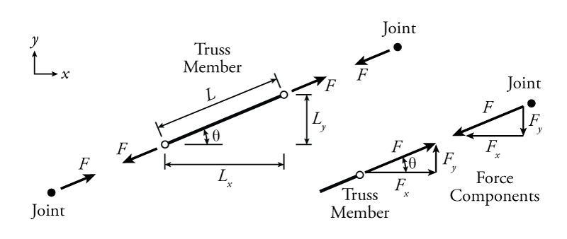
3.2 calculating x and y force components in truss members | learn ...
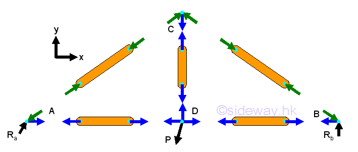
Free body diagram of a 2-bar truss The joint resolution method requires us to evaluate the sum of the forces meeting at a joint. These forces can be resolved into two orthogonal (mutually perpendicular) directions allowing us to evaluate two equations of force equilibrium. Thus we have two equations from which we can determine two unknowns.

Pinned truss freebody diagram (fbd) | stress ebook llc.
If a section is created by slicing away members of a truss that connect to a joint and has an applied load, should that load be considered in the equilibrium equations? Log in to Reply. Dan says: October 21, 2021 at 5:34 pm. When I draw the Free Body Diagram, do I have to include the section that I don't need for solving? Log in to Reply ...
Example 1
รูปที่ 7 แสดง Free Body Diagram ของการใช้วิธี Method of Sections ในส่วนที่สี่ ใช้วิธี Method of Joints เพื่อคำนวณหาแรงที่กระทำกับชิ้นส่วนในแนวขวาง (Cross Member) 3, 7 และ 11

The truss supports a 10-kn load at c. (a) draw the free-body ...
... theoretical determination of the forces in the members of the truss is done by assuming that each member of the truss is in static equilibrium. Figure 6 is ...

Draw the free body diagram of the truss. determine: a) why is ...
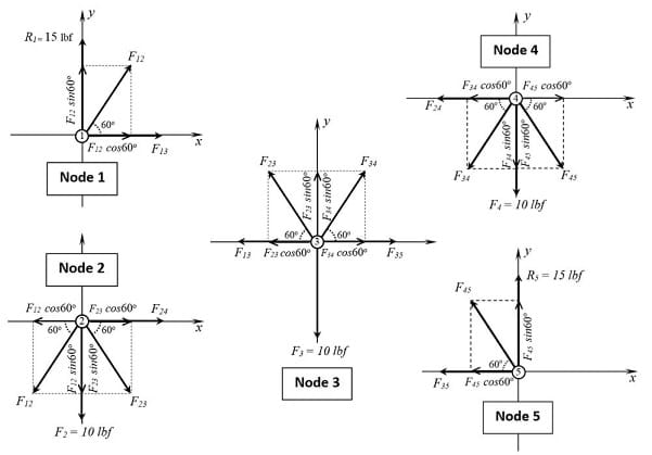
Using the above Free Body Diagram, we can obtain the following formulae: Sum of forces in the y-direction: Sum of moments about node 7: Sum of forces in the x-direction: Final Solution. We can use these results to solve the remaining members in the truss structure.
Solved draw the free body diagram of the truss. find the | chegg.com
The methods used for carrying out the analysis with the equations of equilibrium and by considering only parts of the structure through analyzing its free body diagram to solve the unknowns. Create a structural optimization algorithm capable of finding the various reactions, when subjected to various load combinations and design constraints.
5.6: methods of truss analysis - engineering libretexts
In the method of sections, a section is of the truss is cut, such that not more than three unknown forces are required to be computed. A free-body diagram is drawn for either of its two parts. Three equilibrium equations i.e. ΣF X = 0 ,ΣF Y = 0 and ΣM = 0 for a plane are used to find out three unknown forces.
Analysis of structures
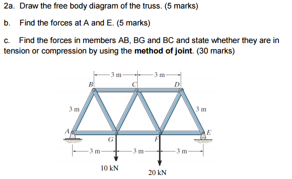
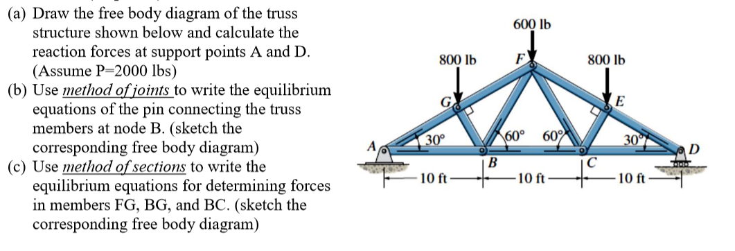
1 Answer to Draw the free body diagram of the truss by passing an imaginary section through members GH, BG, and BC (5 points). a) b) Using method of sections, determine the forces in members GH, BG, and BC of the truss and indicate if the members are in tension or compression (15 points). Set L-4m. 3 m
Solved draw the free body diagram of the truss structure | chegg.com
free-body diagram: A simple diagram that shows all the forces acting on an isolated body. lever arm: The perpendicular distance from the rotation axis to the force application point. static equilibrium: A body is in static equilibrium when it is stationary and when the net forces and torques acting on the body are both zero.
Methods of simple truss analysis | engissol ltd.- structural ...
4) A pop-up will come up with the hand calculations. On the left is a menu you can click through to go through the introduction, evaluation of your structure, (if there are any issues with stability or determinacy), and then the free body diagrams and equilibrium equations for reactions and joints.
Trusses | engineering library
The Free-Body diagram is shown. T-02 is a truss which is pinned to the floor at point A and supported by a roller at point D. Kak Razrezat Trubu Pod Uglom 45 Ili 90 Gradusov Welding Projects Metal Working Welding Determine the force to all members of the truss.

Statics ebook: 2-d trusses: method of joints
Find out more about the truss rod below. Neck Plate. A guitar neck plate helps to spread the load of the pressure exerted by the screws where the neck is mounted to the body. They are only found on guitars with bolt-on necks. Guitar Parts Explained - The Body. The body is the section of the guitar where you will strum or pick the strings.
6 7 analysis of trusses by the method
The free-body diagram is shown below where A y and B y are the vertical reactions at the supports: We firstly want to consider the sum of moments about point B and let it equal zero. We have chosen point B to prove this can be done at either end of the beam (provided it is pin supported).

Part a the truss is supported by a pin at a and a roller at b ...
: This method uses free-body-diagrams of sections of the truss to obtain unknown forces. · In the method of sections one can write three equations for each free- ...
Trusses, frames and machines: analysis of statically determinate ...
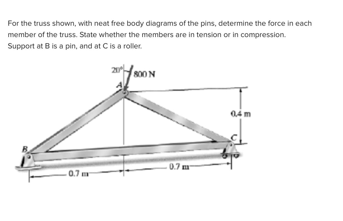
Answered: for the truss shown, with neat free… | bartleby
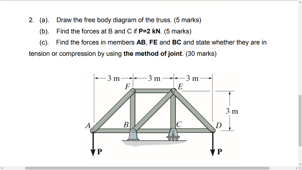
Solved 2. (a). (b). (c). draw the free body diagram of the | chegg.com
Truss examples
Lab: simple form truss - ap physics 1 online

Truss geometry and free-body diagram | download scientific diagram
Doing the math: analysis of forces in a truss bridge - lesson ...
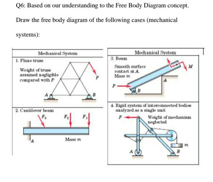
Answered: q6: based on our understanding to the… | bartleby
Medeek design inc. - attic truss analysis

Mechanics map - method of joints
The analysis of trusses
Determining the direction of internal forces in a truss ...
Doing the math: analysis of forces in a truss bridge - lesson ...

Free body diagram of the truss. | download scientific diagram
Truss free body diagram & initial conditions | physics forums
Forces in structural trusses
0 Response to "36 truss free body diagram"
Post a Comment