37 push to exit button wiring diagram
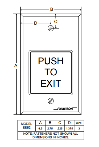
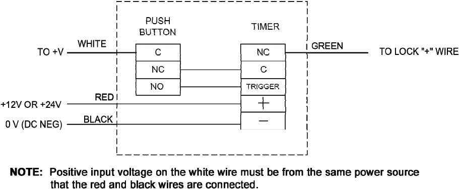
Note: The red and white wires from the EEB2/3N must receive voltage from the same power supply. Weather Option: WCC and WBB available for all Single Gang Push Buttons, Keyswitches and Keypads. Safety Notice: Securitron's UL294 certification indicates that when the EEB is used with the XMS Motion Sensor, it meets the NFPA Life Safety Code 101 requirements for exit of access controlled egress doors. Depressing the push button would close the circuit, allow power to flow and release the strike. Power Supply may be AC or DC, depending on the requirements ...9 pages
Push To Exit Button Wiring Diagram from s1.manualzz.com Effectively read a cabling diagram, one provides to find out how typically the components in the program operate. For instance , in case a module is usually powered up and it sends out the signal of fifty percent the voltage plus the technician does not know this, he'd think he offers an ...

Push to exit button wiring diagram
Common Wiring diagrams. wiring diagram for QEL panics mag lock wiring diagrams. chexit wiring diagram. lever locks for fire doors. emergency release tool. two single doors with panic bars. two single doors with panic bars. push button release electric strike. - WIRING INSTRUCTIONS— magnetic lock or fail safe strike with button, keypad and PIR ... Awesome Push Button Ignition: Here's a fun project that I did to my very first car. When I first got it I was quite happy with my purchase, but soon after that I found that I really wanted a sweet push button ignition and an engine kill switch, like a rocket or a race car or som… Mike Binzer · For questions about this page, or to report problems, please contact Mike Binzer · Revised 1/8/18
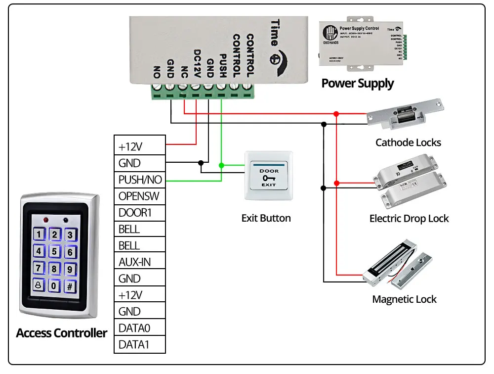
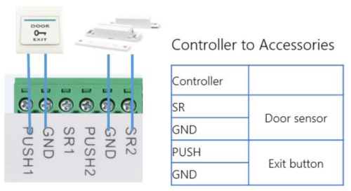
Push to exit button wiring diagram. THIS WIRE DIAGRAM, BE SURE ALL PRODUCTS ARE VOLTAGE COMPATIBLE. (3) ALL WIRING MUST CONFORM TO NATIONAL, STATE AND LOCAL CODES. ... Pressing the code compliant "Push to Exit" push button will bypass the keypad and motion sensor, unlocking the magnetic lock for a fixed 30 seconds. How to wire an Exit Button or Sensor Description. This wiring diagram is to describe where to wire door exit button/ Sensor to Dahua Access controller. Prerequisites. 1. Door Exit button/ sensor 2. DHI-ASC1204B Wiring Diagram The following common wiring diagrams are available: One Single Door with Panic Bar. Electric Latch Retraction, with Auto Operator ... Remote push button with Electric Latch Retraction - Fire Rated Application; ... riser diagrams falcon exit devices 2, The wiring diagram from a push exit button to access controller. we suggest to use 2 cores cable, the diameter is above 0.3mm². 3, The wiring cable from the electric door lock to access controller. We suggest to use 2 cores electronic cable, sectional area is above 1.0 mm².
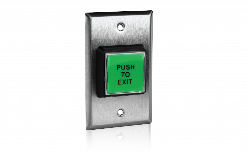
(Product Replaced as of March 2020) How to Wire Outdoor Reader Magnetic lock and Exit button Kit. For additional information, visit us: https://www.fpc-secu... We send a card with these diagram with every order. ... All other billet buttons are rated @ 5 AMP. But… · We do not recommend running anything directly from the button that pull any significant draw; even if they are rated for 3 to 5 amps it is best for them to be wired in pair with a relay. The model 4399 is a spring loaded momentary 2" square, exit button, ... the installer may use push on connectors to which wires are crimped.2 pages Wiring Diagram Electromagnetic Door Lock, EM Lock, Push Button, Power Supply 12v, Carane ngonek kunci magnet.
915Mhz. Wireless Door Control System. 2" Sq. LED Illuminated Exit Switch, w/ timer. CM-30 Series UL compliant LED illuminated 'request to exit' (REX) switches conform to NFPA code requirements and are ADA compliant. They are designed to control electric locks, electromagnetic locks, electric strikes and low energy door operators. At Visionis you can find a wide variety of indoor push to exit buttons that can be used for virtually any indoor application, office, residence, etc. August 26, 2021 - A blue ring halo LED illuminates when the push button is pressed. Can also be wired so that the push button switch is always lighted. A wiring diagram is provided. Push Buttons and Control Stations (Control Pilot Devices)
SAMPLE WIRING DIAGRAMS. SECURITY DOOR CONTROLS ... HANDS FREE & ADA COMPLIANT LATCH RETRACTION EXIT DEVICE APPLICATION 13 ... Push Button (Exterior) PUSH TO OPEN PUSH TO OPEN Push Button (Interior) (COM) (N/O) (COM) (N/O) GRN (Closed Loop) Remove factory installed jumper 13
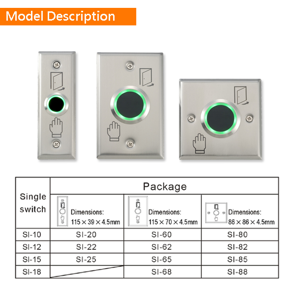
23 Mar 2020 — Door Exit Button Switch, Push Button For Door Access Control Door Exit Button Switch, Push Button For Door Access Control Size Door Exit.

PUSH TO EXIT or REX Button In the event of an emergency, a PUSH TO EXIT or REX button must be included (per code requirements) when connecting a REX device to a maglock. A push-to-exit button does exactly what its name implies: It allows you to exit when you push it if your door doesn't open with the REX or traditional handles.
May 4, 2020 - 15+ Car Start Button Wiring Diagramcar push button start wiring diagram, race car push button start wiring diagram,Car Diagram - Wiringg.net
GymMaster gym software helps you manage your health club, grow your membership base, and run your business from anywhere

CM-9700/9710: 2" Piezoelectric Push/Exit Switch. Camden Heavy-Duty CM-9700 series is a one piece all aluminum construction with a non-moving Piezo actuator. CM-9800 Series illuminated switches are 'light touch' capacitive switches that are both water and vandal resistant. The cast metal construction, easy operation and high visibility of these ...

3. Route the wiring as necessary through the wiring entrance (refer to Figure 2). For surface wiring, use the break out wiring entrance on the front cover (at the same end as the wire entrance). 4. Loosely mount the back cover to the mounting surface using the supplied mounting screws. 5. Mount the detector module to the back cover. Aim the ...

Push to Exit Button Wiring Diagram (1) Push-button dry contact rating: 10A/125VAC For safe operations, do not exceed the ratings above. (2) For normally open requirements, connect wires to N.O dry contact of PUSH-BUTTON (3) For normally closed requirements, connect wire to N.C dry contact of PUSH-BUTTON How to Replace the Plastic Sheet Rotary ...

A leading wholesale distributor of products from top names in door hardware and security technology. Order online 24/7. Same-day shipping. GSA Contract Holder.
Aug 30, 2020 - Push button Ignition Switch Wiring Diagram . Push button Ignition Switch Wiring Diagram New. Push button Switch Wiring Diagram New Push button Switch Wiring. Simple Push button Wiring Enthusiast Wiring Diagrams •. Push button Switch Wiring Diagram 2018 Ignition Relay Wiring Diagram

Paxton exit button - E50. Part No: 356-310. Quick ref: 0217770. Login or register to see prices. In Stock.

June 3, 2020 - Push-Buttons are normally-open tactile switches. Push buttons allow us to power the circuit or make any particular connection only when we press the button. Simply, it makes the circuit connected when pressed and breaks when released.

Connecting the Push to Exit Button (Entry Control).Apr 15, · Controls: Master Volume, Master Tone with Push/Pull Coil Select Feature. If anyone could help me out with a wiring diagram or maybe where to look for one or even suggest a really good tech in the Portland Oregon area I would really appreciate it.
August 28, 2015 - Open-source electronic prototyping platform enabling users to create interactive electronic objects.

Apr 17, 2015 - RELAY CONTACTOR WITH PUSH BUTTON ON/OFF CONTROL
Game show push button wiring

Suitable for applications both indoors and outdoors, STI has a variety of emergency buttons, round push switches, fire alarm buttons, 3-in-1 push button, call point switches, and multipurpose push button switches. Many are UL, cUL and ADA.
Electrical Solutions Corp automates industrial equipment, plants, and processes... from design through installation, testing and startup.
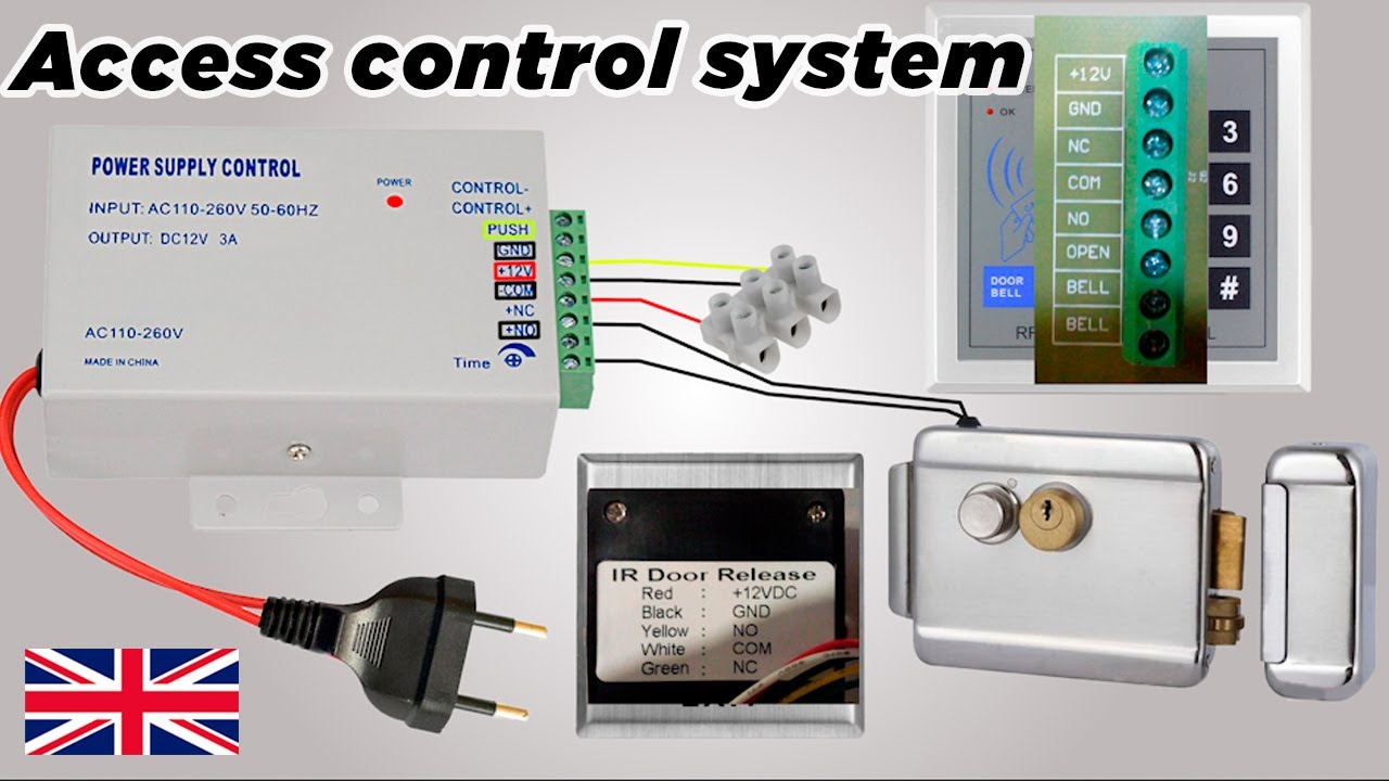
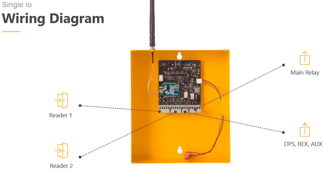
A crucial step in setting up your push-to-exit button is properly wiring all the components. In an IP system like Kisi, this will involve the door lock, the access reader, the controller, the power supply, and the push-to-exit button (as well as optional contact sensors).

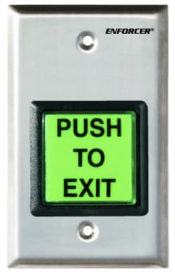
The TS-2T request to exit station with electronic timer and square push button, provides a convenient way to keep the door unlocked for a specified amount of time, allowing for easy entry or egress. The door will relock when the relay time has expired. Features. Standard Features. Switch mounted on single gang wall plate with 430 stainless ...
Typical Wiring Diagrams For Push Button Control Stations 3 Genera/ Information @ Each circuit is illustrated with a control circuit (continued) schematic or line diagram and a control station wiring diagram. l The schematic or line diagram includes all the components of the control circuit and indicates their

Relay Terminals. 5. Exit Button Terminals. 6. RFID Reader Sockets. 6. Sample Wiring Diagrams. 8. Fail-Secure. 9. Fail-Secure with Emergency Exit.17 pages
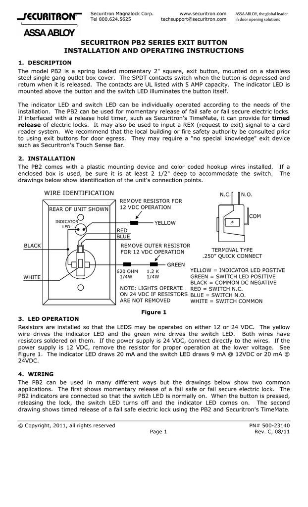
identification of the wires and a typical wiring diagram showing a power supply, motion detector, push button and Magnalock so as to comply with the BOCA code for access controlled egress doors. There is a point to note about the internal design of the unit. Both the push button contacts and
ASSA ABLOY - The global leader in door opening solutions
A forum community dedicated to router and woodworking professionals and enthusiasts. Come join the discussion about different types of routing and routers, shop safety, finishing, woodworking related topics, styles, tools, scales, reviews, accessories, classifieds, and more!

In an IP system like Kisi, this ... and the push-to-exit button (as well as optional contact sensors). The following diagram outlines the setup with an electric strike lock. The “control panel” in question comprises an access controller and a dedicated power supply. The typical REX button has 5 wires, (+, -, COM, ...
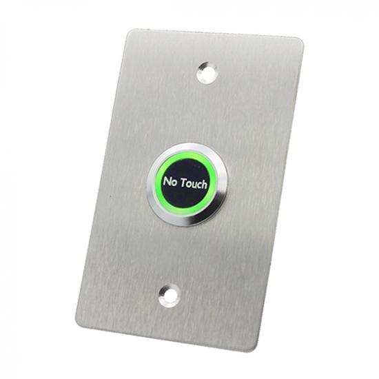
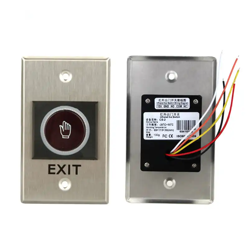
The ENFORCER No-Touch Request-To-Exit Sensor uses IR technology to request egress from a protected a... Add to Compare. SD-927PKC-NSVQ. Wave-To-Open Sensor with Manual Override Button - Spanish. The ENFORCER Wave-To-Open Sensors use IR technology to request egress from a protected area or activ... Add to Compare.

Search Wiring Diagrams for HES and Securitron products. Use the fields below to narrow down your search. You can also view all Wiring Diagrams by leaving the fields blank and clicking the "Search" button. PRO TIP: Be Broad! There are additional filters on the Results page to further narrow down your search.

April 15, 2019 - We will now look at wiring a click plc with selector switch and pushbuttons. A push button (pushbutton) is a simple human interface for controlling some aspect of a machine or process. The push button requires a force to push the button to change the electrical operation from off to on or vice v ...

Wiring Diagram 2N Helios IP Verso with Fail Secure Lock, Exit Button and 2N Security Relay The wiring diagram below shows how to wire a fail secure strike lock into the 2N Helios IP Verso when powered via Power over Ethernet (PoE). It also shows how to connect an exit button and 2N Security Relay.
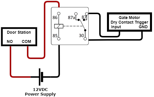
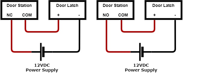
In the diagram below the INTIPRDSG Door Station is being used and is utilising the 12V output. This can be substituted for a 12VDC Power supply. Push-To-Exit Button. If you require a push to exit button, ensure it is a NO button. Wiring the latch as per one of the three diagrams, then connect your button.
TS-2 Request to Exit Station The TS-2 request to exit station, with square push button, provides a convenient way to add authorized access control to a variety of applications. Features
Piezoelectric push buttons for indoor or outdoor use (IP65). LED ring around button changes from green to red or red to green when the button is pressed. Timed or toggle output. Includes separate manual override button in case power to piezoelectric push button fails. Relay rated 2A@30VDC with two individually programmable outputs (NO/NC).

The push to exit button is connected to the access control application, which controls the locking mechanism of the door, using wires. Any individual that needs to exit the building or pass through the door simply has to push or press the button. When pushed, it momentarily releases the fail-secure or fail-safe lock of the door.
- WIRING INSTRUCTIONS— fail secure strike with one button Power Supply Push Button N/O Fail Secure Strike Polarity Insensitive Depressing the push button would close the circui t, allow power to flow and release the strike. Power Supply may be AC or DC, depending on the requirements of the strike.
Mike Binzer · For questions about this page, or to report problems, please contact Mike Binzer · Revised 1/8/18
Awesome Push Button Ignition: Here's a fun project that I did to my very first car. When I first got it I was quite happy with my purchase, but soon after that I found that I really wanted a sweet push button ignition and an engine kill switch, like a rocket or a race car or som…
0 Response to "37 push to exit button wiring diagram"
Post a Comment