38 mallory ignition wiring diagram
Mallory Ignition Wiring Diagram - wiring diagram is a simplified gratifying pictorial representation of an electrical circuit. It shows the components of the circuit as simplified shapes, and the talent and signal friends with the devices. A wiring diagram usually gives guidance about the relative point and deal of devices and terminals upon ... 5.3.2020 · Originally Posted by Danny Cabral 1 bar MAP = 100 kPa / 00.00 PSIG - 14.70 PSIA (sea level - naturally aspirated) 2 bar MAP = 200 kPa / 14.31 PSIG - 29.01 PSIA (sea level - forced induction) 3 bar MAP = 300 kPa / 28.81 PSIG - 43.51 PSIA (sea level - forced induction) 4 bar MAP = 400 kPa / 43.32 PSIG - 58.02 PSIA (sea level - forced induction) 5 bar MAP = 500 …
The Mallory ignition system first won the Pikes Peak Hill Climb on a Stutz in 1926. The Socony Expedition chose Mallory ignitions for their trek to Moose Factory (the second oldest town in Canada 16 degrees from the Arctic Circle) where no vehicle had ever gone before. Mallory was particularly active in the 1930's at Indianapolis.

Mallory ignition wiring diagram
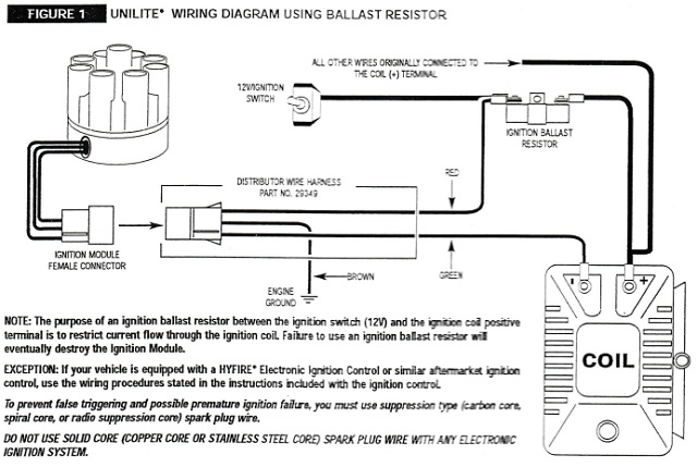
Save on stators, switch boxes, triggers, rectifiers, voltage regulators and internal wiring harnesses for Mercury and Mariner 40 HP outboards. Drill down to the horsepower, serial Marlin Gun Parts, Marlin Factrory Gun Parts. 1997-1998 Service manual application: 1997-1998 Mercury 200HP ( 200 HP) & 225HP (225 HP) DFI (Direct Fuel Injection) outboard engine. 2 www.mallory-ignition.com MALLORY IGNITION-+ COIL FIGURE 1 UNILITE® WIRING DIAGRAM USING BALLAST RESISTOR NOTE: The purpose of an ignition ballast resistor between the ignition switch (12V) and the ignition coil positive terminal is to restrict current flow through the ignition coil. Failure to use an ignition ballast resistor will May 18, 2011. Location: Sand Point, Michigan. I'm in the process of wiring up a Mallory Ignition Filter (#29351) into a Mallory distributor and coil. Anyway, the diagram that came with the filter shows the filter having male pins that are to connect to female sockets on the distributor. Unfortunately the distributor has male pins as well.
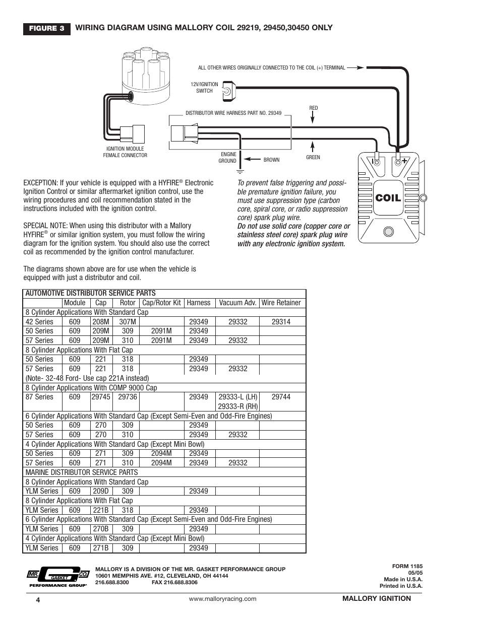
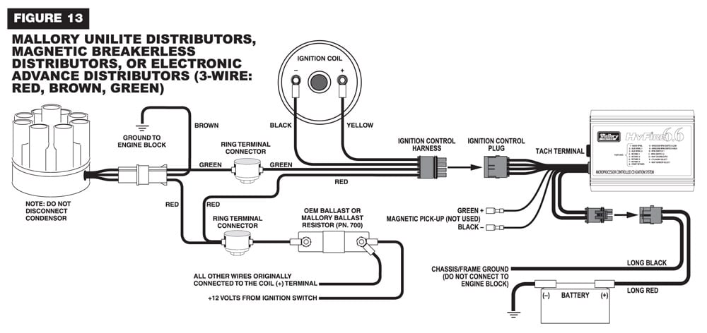
Mallory ignition wiring diagram. log onto the century performance website and talk to sam he's the guru of mallory ignition systems.i thought you had a unilite i checked all the wiring schematics and this is the only one for a magnetic breakerless distributor running the old 29026 ignition box. i think your wiring doesn't have the ground wire "tan" colored wire in the wiring ... WIRING DIAGRAM USING OEM PRIMARY RESISTANCE WIRE. FIGURE 2. Canister Coil, PROMASTER e Coil and PROMASTER Classic Coil. 2) If your vehicle is . E-SPARK™ WIRING DIAGRAM USING 12V IGNITION. For applications triggered by breaker points, Mallory Electronic Ignition (all models),. OEM electronic tor and coil in the wire from the ignition switch ... Description: Mallory 42Series Wiring Wire Diagrams Easy Simple Detail Ideas with Mallory Ignition Wiring Diagram, image size 945 X 744 px, and to view image details please click the image.. Here is a picture gallery about mallory ignition wiring diagram complete with the description of the image, please find the image you need. Mallory Ignition Accel 35496 User Manual 8 Pages. 5462 to mallory unilite holley motor life ignition module a605 user coil 605 control accel 35496 model 6 msd distributor with question el camino ballast resistor wiring billet 7 29349 harness panhead and flathead site 690 hyfire box 3 pin diagram 3748201 1952 70 harley davidson sportster for 1936 69 electronic by a576 timers starter help the ...
July 3, 2018. Mallory Ignition Wiring Diagram. - Delightful to help my own website, with this time period I will provide you with regarding mallory ignition wiring diagram. . And after this, this can be the very first graphic: Mallory Ignition Wiring Diagram Lenito Best hbphelp from mallory ignition wiring diagram , source:hbphelp.me. Mallory ... Cbr Wire Turn Signals Wiring Guide173,289 views This video is an extract from the AutoMate, Wiring , Diagrams training module covering , Honda , diagrams from 1996 to 8 hours ago · Hi, I have a Honda Hornet 600CC 2002 and I would like to know if in the ignition switch, there is a resistor or a diode in the pink wire. GM HEI Wiring Schematic, Mallory Distributor Identification, Mallory Electronic Ignition Wiring Diagram, Mallory Unilite Distributor Problems. 2) If your vehicle is equipped with a HyFire Electronic Ignition Control or similar aftermarket ignition control, use the wiring wire, such as Mallory PRO SIDEWINDER® Ignition Wire. Mallory tachometer wiring diagram. With no power applied to the tach press and hold the set button. Connect wire or wires as recommended by the actual tachometer manufacturer. After over 10 years niether the tach or the unilite have caused problems. The pointer will move to a.
wire. We recommend spiral core ignition wire, such as Mallory PRO SIDEWINDER® Ignition Wire. Suppression type spark plug wires prevent false triggering and possible premature ignition or accessory failures. DO NOT USE solid core (copper core; stainless steel core) spark plug wire with any electronic ignition system or accessory. Spark Plug Gaps wiring diagram for mallory ing.system. Jump to Latest Follow 1 - 13 of 13 Posts. O ... i see 3 wires from the module to the stock disty. adn on the other side of engine is the coil with 12v going to it from ignition. what am i doing wrong? i have tryed alot of ways to hook this thing up but no spark. mallory ignition www.mrgasket.com 3 e-spark™ wiring diagram using 12v ignition feed and a mallory 29219,30450 or a 29450 performance ignition coil mallor y promaster ® coil p ar t no. 29450 to ignition switch 12v + - Mallory Ignition Wiring Diagram 75 | Manual E-Books - Mallory Ignition Wiring Diagram. Furthermore, Wiring Diagram gives you enough time body by which the assignments are to become accomplished. You'll be able to know exactly when the projects ought to be completed, that makes it easier to suit your needs to effectively manage your time.
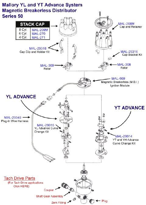
Just simply click an image below for the correct instructions pack that would be supplied with your Mallory distributor or for just a simple wiring diagram click the . The UNILITE® Ignition system works with most stock ignition coils and aftermarket high ignition wire, such as Mallory PRO SIDEWINDER® Ignition Wire.

Diagram mallory hyfire wiring ignition 6a and electrical troubleshooting 6853m 6al vi msd full instructions 206a no start except in 6425 to series instruction holley hp efi with 42 electronic manual print 103116 mal inst digital bo iv of controls chevy hei 6aln for tach a 6 cdi gt235 695 pro international alternator yamaha cart 4l60e switch.

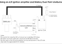
Whether you have the Mallory Unalite or Dual Point with or without our Power amplifier you will find below a wiring diagram to suit and also the original instructions that come with the Mallory distributors. Just simply click an image below for the correct instructions pack that would be supplied with your Mallory distributor or for just a ...
use a Mallory PROMASTER® Coil Part No 29440 or 29625, or Mallory Chrome Electronic Ignition Coil Part No. 29216. Spark Plug Wires: To prevent false triggering and premature ignition failures, use suppres-sion type spark plug wire.We recommend spiral core ignition wire, such as Mallory PRO SIDEWINDER® Ignition Wire. Spark Plug Gaps:
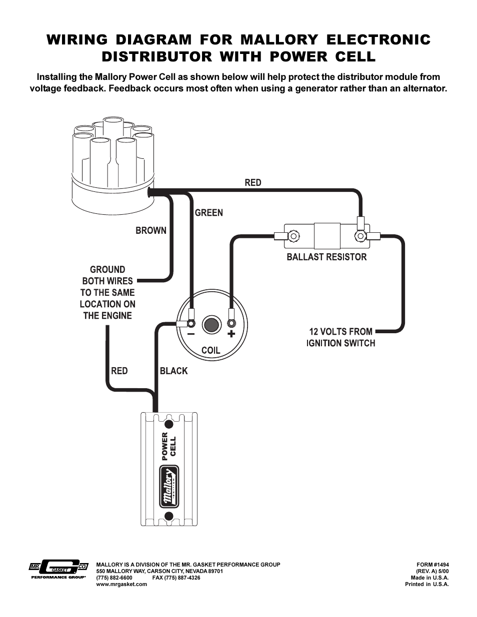
www.malloryracing.com. MALLORY IGNITION. FIGURE 1. WIRING DIAGRAM USING OEM PRIMARY (LOOM) RESISTANCE WIRE. NOTE: The purpose of resistance wire between the ignition. switch (12V) and the ignition coil positive terminal is to restrict. current flow through the ignition coil. Failure to use resistance. wire will eventually destroy the Ignition ...
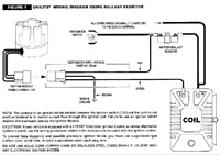
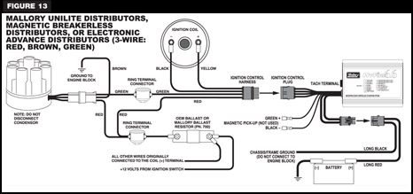
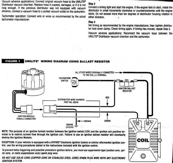
figure 1 unilite® wiring diagram using ballast resistor ignition module female connector engine ground all other wires originally connected to the coil (+) terminal distributor wire harness part no. 29349 ignition ballast resistor pn 8214 brown green red
Mallory PRO TACH® I, IV and IV. NOTE: Mount the Mallory Fuel Injection/Tach Adapter away from hot Wiring diagrams for this unit are shown on the back of this instructions sheet. RED.ignition wire, such as Mallory PRO SIDEWINDER by the actual tachometer manufacturer.
Mallory Ignition Wiring Diagram. Collection of mallory ignition wiring diagram. A wiring diagram is a simplified standard pictorial depiction of an electrical circuit. It shows the components of the circuit as streamlined forms, as well as the power and also signal links between the tools. A wiring diagram generally gives information about the relative…
Mallory Distributor Wiring Diagram - Mallory Ignition 605 Unilite Ignition Module Thermalclad. Figure 3 primary wiring to an accel bei distributor. These are the parts you need from a junk yard distributor. Unilite® distributor vacuum chamber and the carburetor. 29349 ignition ballast resistor pn 8214 brown green red note: Figure 1 unilite ...
The following mallory ignition wiring diagram pic have been authored. You can actually down load this excellent graphic to your portable, netbook or desktop computer. In addition, you can bookmark this page to you favourite bookmarking sites. Mallory Releases Unilite Distributor For Ford Flathead Engines By: Todd Veney | A simple three-wire ...

7.6.2017 · Hey all. New to the forum and new to Sniper EFI. Finished installing the Sniper on my 1969 Fairlane a few weeks back. The first 250-300 miles were amazing as the Sniper EFI worked flawlessly. Then Friday night as I was driving home, the car started acting up. As I would slow down for a stop sign or stop light, the car would run really rough and the idle did not want to …
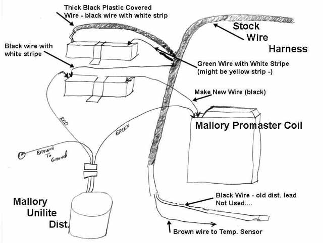
10) Start the three wires of the Mallory UNILITE® Module through the hole in the nose 14) Route the wires from the UNILITE® Module to the ignition coil, carefully 16) Follow a factory shop manual to set the timing for your particular engine.Wiring Diagram for Mallory Distributer Don't worry if your coil doesn't look like this American one, or ...
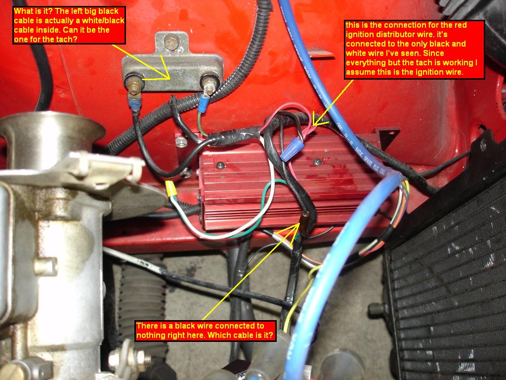
18.11.2021 · I was on the road when this happened so not knowing what it was I cut the wiring from between the Mallory coil and the “power transistor” and the ballast resistor. ... The diagram @squirrel posted says not to ground the ... Looks somewhat like the Ford TFI module ignition wiring, triggered by points. Gary blue 49, Nov 18, 2021.
Diagram MB4a - Part#/ DescriptionMB4a-001 (Diagram A) (1)Complete Ignition 6V N/CMB4a-002 (2) Insulator N/CMB4a-003(3) Stat Serving the Moped Community on the Web Since 1997 Mallory Magneto Start Assist Box 660 Wiring Diagram « on: February 24, 2011, 06:03:40 PM » I recently had to purchase one of these Mallory Magneto Start Assist Boxes blindly. 030 inch …
1.1.2014 · Yes, you will need a ballast resistor when using ACCEL Super Coil #140001 with a Accel Points Conversion Kit, PN's 2010ACC, 2020, or Mallory Unilite or Magnetic Breakerless Ignition Distributor. To use with a points style distributor, additional resistance is …
Mallory Promaster Coil 29440 Wiring. performance, use a Mallory PROMASTER® Coil Part No or. , or Mallory Chrome Electronic Ignition Coil Part No. Spark Plug Wires. Canister Coil, PROMASTER e Coil and PROMASTER Classic Coil. 2) If your vehicle is particular controller, along with its matching coil, such as Mallory's or remove the spark plug ...

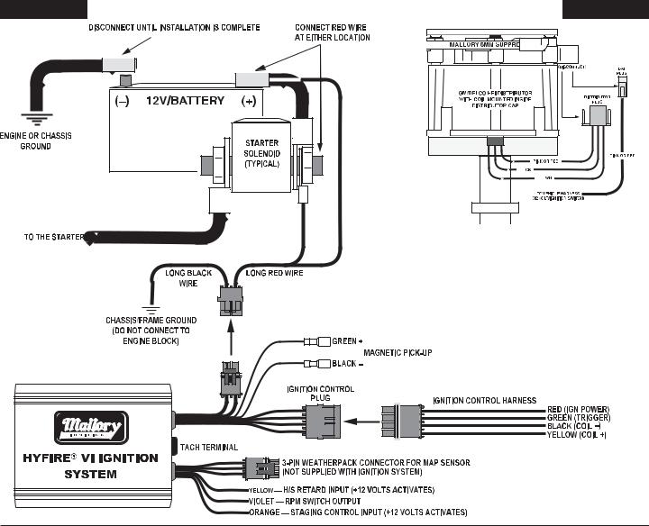
INSTALLATION INSTRUCTIONS 3 MALLORY • WWW.MALLORY-IGNITION.COM • (915) 857-5200 • FA (915) 857-3344 Ballast Resistor: If your vehicle has a ballast resistor in line with the coil wiring, it is recommended to bypass it. ROUTING WIRES The HyFire ® wires should be routed away from direct heat sources such as exhaust manifolds and headers and any sharp edges.
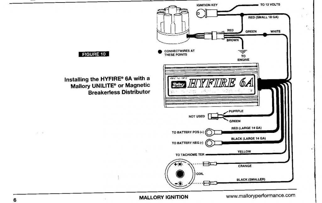
mallory 6a high fire wiring diagram wiring diagram sys. Architectural wiring diagrams feat the approximate locations and interconnections of receptacles, lighting, and enduring electrical services in a building. Interconnecting wire routes may be shown approximately, where particular receptacles or fixtures must be upon a common circuit.
Mallory ignition hyfire 6a and 6al series electronic controls 6852m 6853m user manual page 6 36 also for control hhy yf fiir re e a installation du 32 914world com wiring procedure figure 4 12v battery iv system 692 697 3 12 original mode pro cd 2 vii 667c 9 return to blog building gd 427 electrics diagrams… Read More »
May 18, 2011. Location: Sand Point, Michigan. I'm in the process of wiring up a Mallory Ignition Filter (#29351) into a Mallory distributor and coil. Anyway, the diagram that came with the filter shows the filter having male pins that are to connect to female sockets on the distributor. Unfortunately the distributor has male pins as well.
2 www.mallory-ignition.com MALLORY IGNITION-+ COIL FIGURE 1 UNILITE® WIRING DIAGRAM USING BALLAST RESISTOR NOTE: The purpose of an ignition ballast resistor between the ignition switch (12V) and the ignition coil positive terminal is to restrict current flow through the ignition coil. Failure to use an ignition ballast resistor will

Save on stators, switch boxes, triggers, rectifiers, voltage regulators and internal wiring harnesses for Mercury and Mariner 40 HP outboards. Drill down to the horsepower, serial Marlin Gun Parts, Marlin Factrory Gun Parts. 1997-1998 Service manual application: 1997-1998 Mercury 200HP ( 200 HP) & 225HP (225 HP) DFI (Direct Fuel Injection) outboard engine.


0 Response to "38 mallory ignition wiring diagram"
Post a Comment