37 autometer air fuel gauge wiring diagram
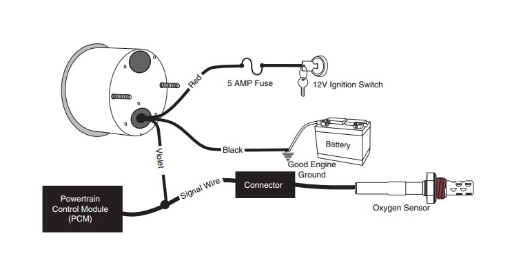
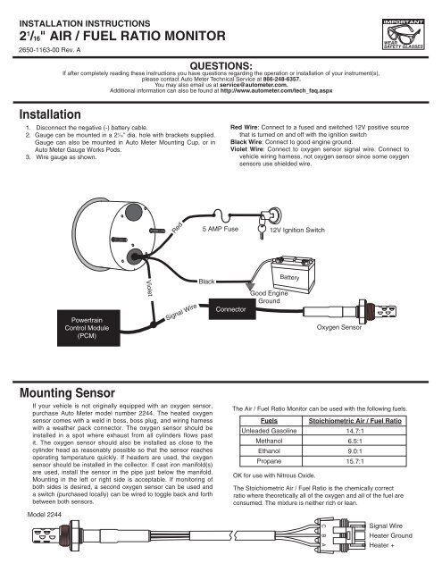
Aug 15, · Autometer Pyrometer Wiring Diagram auto meter ficial site trade in any aftermarket gauges for credit on new autometer gauges 15 trade in trade up read more auto Autometer Pyrometer Wiring Diagram Isspro Electric Water Temp img source: diagramweb.net Autometer Pyrometer Wiring Diagram As Well As Temperature Gauge img source. Gauge can be mounted in a 21⁄16" dia. hole with brackets supplied. Gauge can also be mounted in Auto Meter Mounting Cup, or in Auto Meter Gauges Works Pods. Wire gauge as shown. Red Wire: Connect to a fused and switched 12V positive source that is turned on and off with the ignition switch. Black Wire: Connect to good engine ground.
Sep 10, 2021 · Wiring diagram for auto meter new wiring diagram auto gauge a newbie s overview of circuit diagrams. Toll free tech support. Pin On Gauges . Higginbotham fuel gauge wiring diagram rate fuel gauge wiring autometer gauge wiring diagram additionally wiring diagram provides you with enough time frame by which the assignments are to be accomplished.

Autometer air fuel gauge wiring diagram
16.2.10 Fuel pump 16.2.10.1 Working principle of fuel pump: The electric oil pumps and pressure regulator works together to provide 250Kp gas pressure to the engine, installed at the bottom of the fuel tank. 16.2.10.2 Appearance of fuel pump: - 145 -... Page 151: Troubleshooting Diagnosis 16.2.10.3 Fuel pumps fault diagnosis: 1. Auto Meter Products. 413 W Elm St. Sycamore, IL 60178. Toll Free Tech Support: 866.248.6357. Toll Free Customer Service: 866.248.6356. International: 815.895.8141 18 gage, wire from fuel tank to gauge. If a new hole is drilled in the firewall a grommet is recommended. Connect one end to terminal post on fuel level sender and the opposite end to the sender (S) terminal spade on back of gauge. 2. Connect ground wire from ground post on gauge to suitable chassis ground. 3.
Autometer air fuel gauge wiring diagram. Fuel Level. 1. Gauge connects to fuel sender on fuel tank. Existing wires may be used, or route proper length of 18 gage, wire from fuel tank to gauge. If a new hole is drilled in the firewall a grommet is recommended. Connect one end to terminal post on fuel level sender and the opposite end to the sender (S) terminal spade on back of gauge. 2. Hi Steve, thank you for connecting with us. Our Pro Series Wideband can read an air/fuel ratio range of 6:1 to 20:1, which includes unleaded gasoline, methanol, and ethanol. While pure gasoline has a stoichiometric ratio of 14.7:1, 10% ethanol with be 14.04:1. Answered by: Matt from AutoMeter. Date published: 2018-02-07. Air Fuel Ratio Gauges & Kits Here at AutoMeter, we offer a wide selection of industry-leading Air Fuel ratio gauges to keep your vehicle from running too rich or too lean. With our vast assortment of both narrow band and wideband air fuel gauges to monitor your motor, avoiding expensive repairs has never been easier. Autometer Air Fuel Gauge Wiring Diagram Rate Fuel Gauge Wiring – Autometer Gauge Wiring Diagram. Additionally, Wiring Diagram provides you with enough time frame by which the assignments are to be accomplished. You will be able to learn exactly once the projects should be completed, that makes it easier for you to correctly manage your time ...
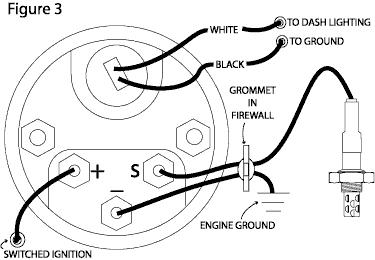
Autometer Boost Gauge Wiring Diagram. How to Install an Auto Meter Pro-Comp Ultra-Lite Air/Fuel Ratio Gauge - Electric on Your M or wiring diagram for your specific vehicle to learn which wire is the signal. WARNING. Do not connect ohm meter to oxygen sensor, or touch wire to ground or power. Damage to oxygen sensor will result. diagramweb.net ... Autometer Air Fuel Gauge Wiring Diagram Rate Fuel Gauge Wiring - Autometer Gauge Wiring Diagram. Additionally, Wiring Diagram provides you with enough time frame by which the assignments are to be accomplished. You will be able to learn exactly once the projects should be completed, that makes it easier for you to correctly manage your time ... 1,719. 35. Jan 19, 2005. Burbank, California. Short version, a wideband O2 uses a seperate sensor that has to be installed in front of your catalytic converter (if so equipped), but gives you a stable, accurate measurement of your air to fuel ratio, usually from 0v-5v, allowing a much finer degree of resolution. Trans Temp Gauge Installation: but an A-pillar gauge mount is available as a professional location to mount two gauges. diagramweb.net has a 2 & 3 gauge pod available Pictured below is a copy of the wiring diagram for the Autometer Transmission Temperature Gauge. STEP 4.
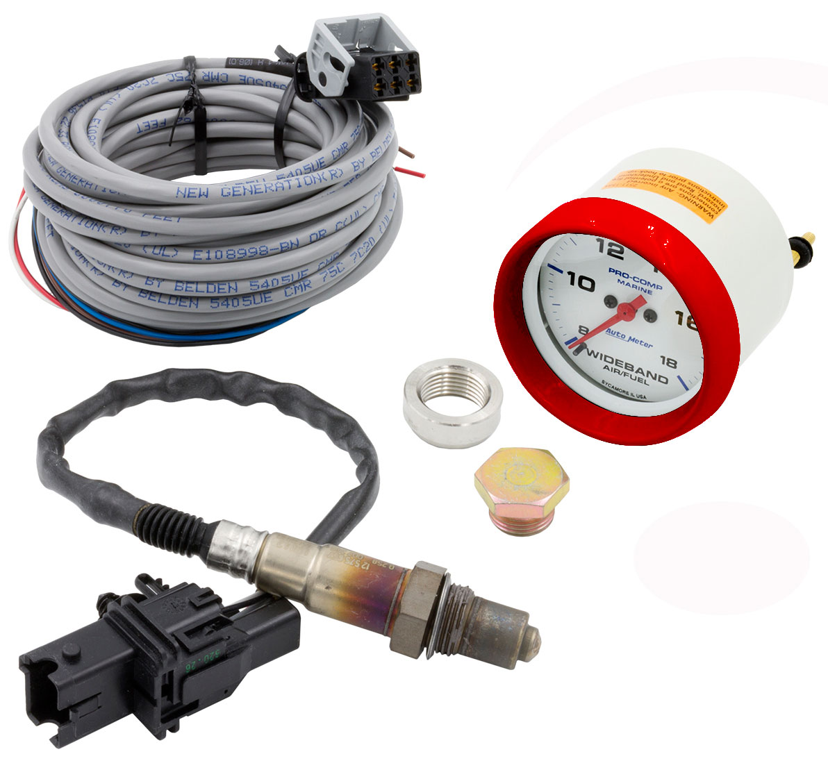
16" AIR / fUeL RATIO mONITOR 2650-1163-00 Rev. A Installation 1. Disconnect the negative (-) battery cable. 2. Gauge can be mounted in a 21⁄ 16" dia. hole with brackets supplied. Gauge can also be mounted in Auto Meter Mounting Cup, or in Auto Meter Gauge Works Pods. 3. Wire gauge as shown. Red Wire: Connect to a fused and switched 12V ... 2. Gauge can be mounted in a 21 ⁄16" dia. hole with brackets supplied. Gauge can also be mounted in Auto Meter Mounting Cup, or in Auto Meter Gauge Works Pods. 3. Wire gauge as shown. Red Wire: Connect to a fused and switched 12V positive source that is turned on and off with the ignition switch . Black Wire: Connect to good engine ground. Type:Digital Stepper Motor ; Range:8:1-18:1 AFR ; Lighting:LED ; Instructions: Download PDF ; Auto Meter Products. 413 W Elm St. Sycamore, IL 60178. Autometer Temperature Gauge Wiring Diagram. kaia.schoen July 8, 2021 Templates No Comments. ... Autometer Air Fuel Gauge Wiring Diagram. Autometer Electric Fuel Pressure Gauge Wiring Diagram. Rosemount 644 Temperature Transmitter Wiring Diagram. Digital Temperature Controller Wiring Diagram. Suzuki Outboard Gauge Wiring Diagram.
SENSOR, O2, KIT, NARROWBAND AIR/FUEL
Fuel Level Gauges Autometer How They Work How To Install Tutorial Instructions Ohms Wiringhttp://www.jegs.com/vct/Auto+Meter/105/1010331-----...

2-1/16
An air fuel gauge can be connected much easier than you might think. It might seem like quite a task at first, but installing and mounting an air fuel gauge in your vehicle is something you can do yourself in a short amount of time. An air fuel gauge will allow you to monitor the changes in oxygen content in the air ...

AutoMeter Products 3315 Fuel Level Gauge 73 E/8-12 F
Autometer Tach Gauge Wiring Diagram. dexter.wehner May 5, 2021 Templates No Comments. 21 posts related to Autometer Tach Gauge Wiring Diagram ... Autometer Air Fuel Gauge Wiring Diagram. Autometer Electric Fuel Pressure Gauge Wiring Diagram. Vdo Tach Wiring Diagram. Suzuki Outboard Gauge Wiring Diagram. Equus Fuel Gauge Wiring Diagram. Yamaha ...

Installation of Auto Meter Cobalt Wideband Air/Fuel Gauge ...
You may use 18g or 20g stranded wire for all fuel level gauge wiring. S = This connects to the sending unit in the fuel tank. **(See Sending Unit Wiring Section) I = Supply 12v, key on power to this terminal. It is recommended to use a 3 Amp automotive fuse when supplying power to this ... Therefore Auto Meter offers gauges in many resistance ...
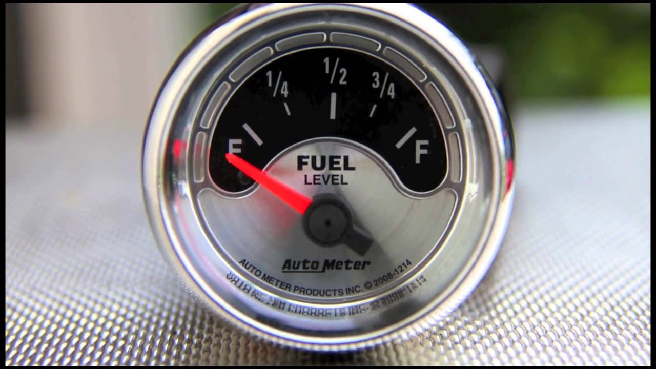
Fuel Level Gauges Autometer How They Work How To Install Tutorial Instructions Ohms Wiring
As stated earlier, the traces in a Autometer Gauge Wiring Diagram signifies wires. Occasionally, the wires will cross. However, it doesn’t imply connection between the cables. Injunction of two wires is usually indicated by black dot on the intersection of 2 lines.
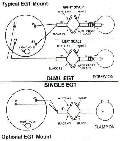
EGT, exhaust gas temperature gauge, Westach, Westberg exhaust ...
16" WIDE BAND AIR/fUEL RATIO mONITOR ® 2650-1143-00 Rev. A Installation 1. Disconnect the negative (-) battery cable. 2. Gauge can be mounted in a 21⁄ 16” dia. hole with brackets supplied. Gauge can also be mounted in Auto Meter Mounting Cup, or in Auto Meter Gauge Works Pods. 3. Wire gauge as shown. 12V Ignition Switch Good Engine Ground
Installation
A wiring diagram is a simplified conventional photographic representation of an electrical circuit. Components available on your auto meter wideband air fuel gauge. Gauge can also be mounted in auto meter mounting cup or in auto meter gauge works pods.

Installing an Air Fuel Ratio Gauge
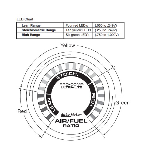
The Auto Meter Air/Fuel gauge has a signal output for supplying information to a Data Logger or engine management system. The signal provided is a linear 0-4 volts output. 0 volts out equals 10.0 Air/Fuel Ratio, 4 volts out equals 18.0 Air/Fuel Ratio. Note: Due to the limitations of the sensor, the indicated Air/Fuel Ratio
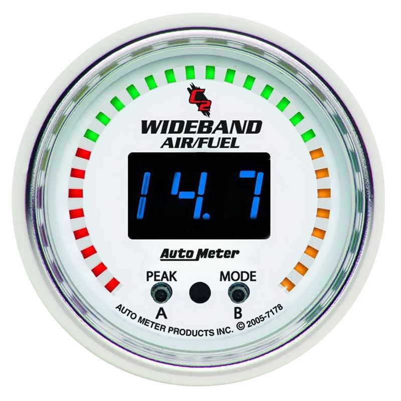
AutoMeter C2 52mm Wideband Air/Fuel Gauge(7178)
For ford fuel injected applications with a schrader valve in the fuel rail use adapter 3280 between the fuel rail and pressure sender. Assortment of autometer oil pressure gauge wiring diagram. Installing an auto meter fuel gauge is an easy task once you have decided how and.

1
Over the years, Auto Meter has established itself as a manufacturer of quality, professional automotive gauges. Adding any Auto Meter gauge to your vehicle will help to ensure accurate and consistent readings from your car or truck. Installing an Auto Meter fuel gauge is an easy task once you have decided how and ...
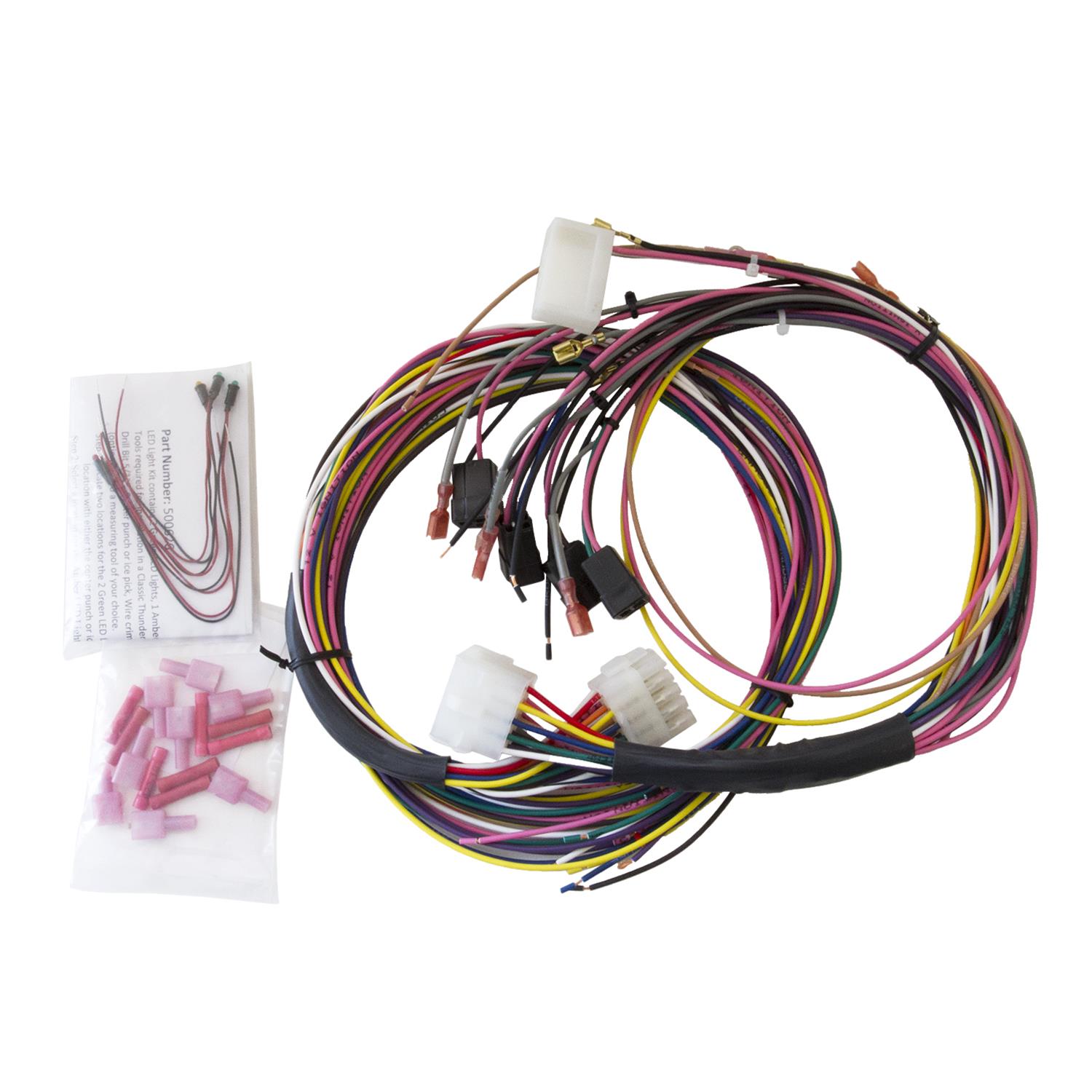
AutoMeter 2198 AutoMeter Universal Gauge Wiring Harnesses | Summit Racing
This digital wideband gauge allows you to closely monitor and tune your car or truck's Air to Fuel Ratio on an ultra bright 4-digit color changing LED display. Select Gasoline AFR readings from 10.01 to 20.00 AFR, E85 readings from 6.66 to 13.31 AFR, or LAMBDA readings from 0.683 to 1.365.

Auto Meter 3370 Sport-Comp Wide Band Air Fuel Ratio Kit,2.3125 in.
Autometer Electric Fuel Pressure Gauge Wiring Diagram. One Line Diagram Symbols. 59 Cummins Fuel Line Diagram. 62 Diesel Fuel Line Diagram. Echo Srm 225 Fuel Line Diagram. Electrical One Line Diagram Symbols. Ge 300 Line Control Wiring Diagram. Ge Refrigerator Water Line Diagram. Gm 38 Engine Vacuum Line Diagram.
Installation mounting Sensor
18 gage, wire from fuel tank to gauge. If a new hole is drilled in the firewall a grommet is recommended. Connect one end to terminal post on fuel level sender and the opposite end to the sender (S) terminal spade on back of gauge. 2. Connect ground wire from ground post on gauge to suitable chassis ground. 3.
Autometer Air / Fuel Ratio Gauge, 2-5/8" - Custom Colored Rims
Auto Meter Products. 413 W Elm St. Sycamore, IL 60178. Toll Free Tech Support: 866.248.6357. Toll Free Customer Service: 866.248.6356. International: 815.895.8141
How-to: Tuning Carbs with an Oxygen Sensor and A/F Gauge ...
16.2.10 Fuel pump 16.2.10.1 Working principle of fuel pump: The electric oil pumps and pressure regulator works together to provide 250Kp gas pressure to the engine, installed at the bottom of the fuel tank. 16.2.10.2 Appearance of fuel pump: - 145 -... Page 151: Troubleshooting Diagnosis 16.2.10.3 Fuel pumps fault diagnosis: 1.

Auto Meter Wideband Air / Fuel Ratio Gauges
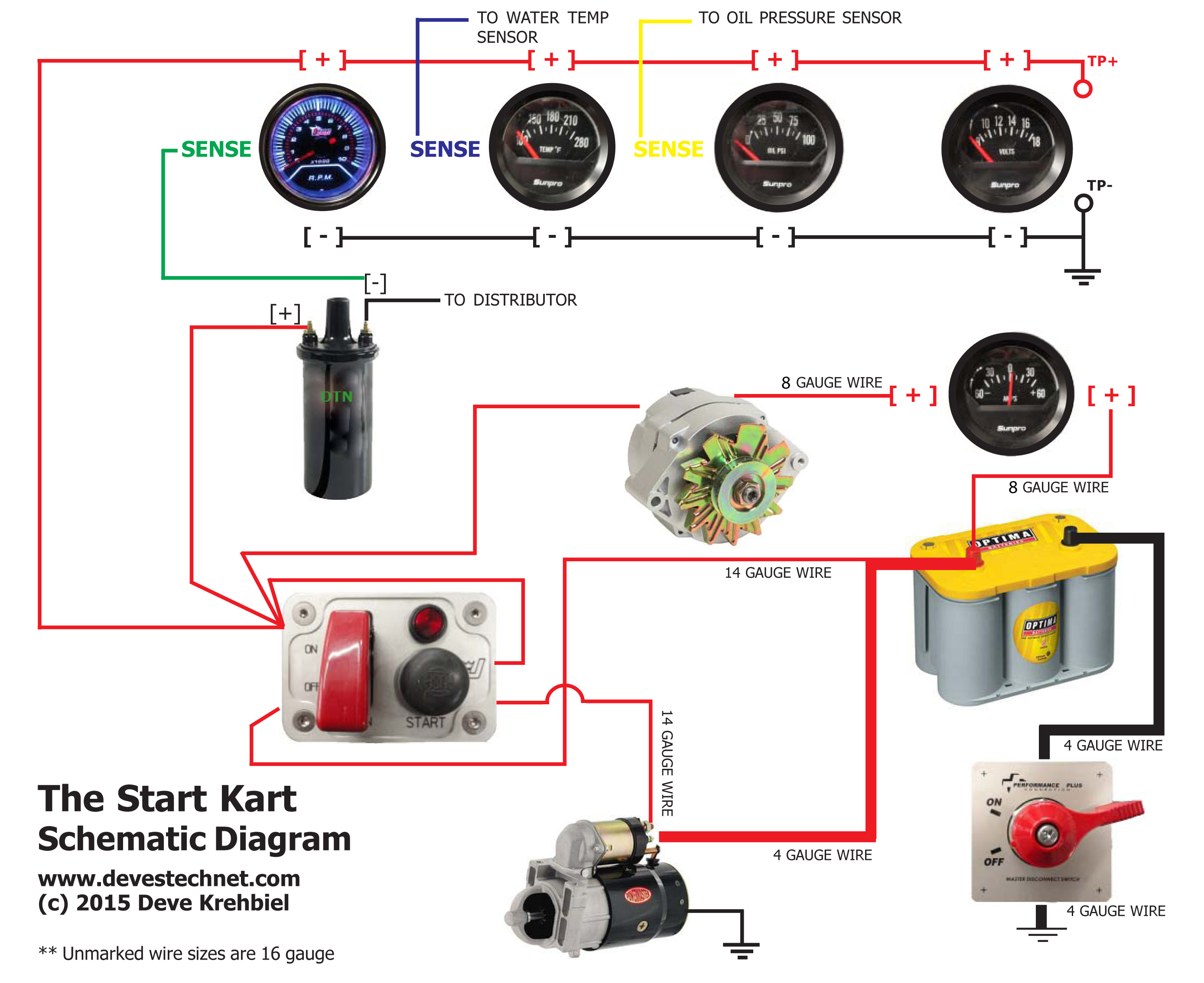
Start Kart Plans

2-1/16
How to Install an Air Fuel Gauge - My Pro Street
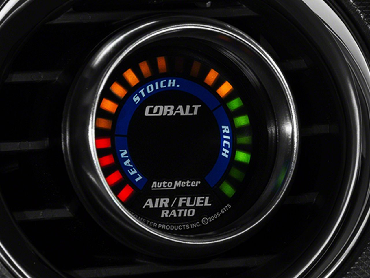
Installation Instructions for Auto Meter Cobalt Air/Fuel ...
Installation Instructions for Auto Meter Cobalt Air/Fuel ...

MTX-L Digital Air/Fuel Ratio Gauge User Manual - PDF Free ...
How to Install Auto Meter Programmable Speedometer Gauge - 0 ...
Auto Meter : User Manual
Tuning Ecu | Page 3 | StangNet

2-1/16" WIDEBAND PRO AIR/FUEL RATIO, 6:1-20:1 AFR, GS

2-1/16

2-1/16" NARROWBAND AIR/FUEL RATIO, LEAN-RICH, PHANTOM
Installation Instructions for Auto Meter Cobalt Air/Fuel ...
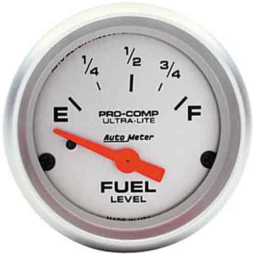
Auto Meter Ultra-Lite Fuel Level Gauge 2-1/16" electrical

Air/Fuel Ratio Gauge

2-1/16

Installation Instructions for Auto Meter Cobalt Air/Fuel ...

DIY Air / Fuel Ratio Meter
21/16" AIR / fUeL RATIO mONITOR Installation ... - Auto ...
Tech Shop

Autometer Oil Pressure Gauge Wiring Diagram | Oil pressure ...
0 Response to "37 autometer air fuel gauge wiring diagram"
Post a Comment