38 accelerator pedal position sensor wiring diagram
Accelerator pedal position sensor wiring diagram wiring diagram is a simplified satisfactory pictorial representation of an electrical circuit it shows the components of the circuit as simplified shapes and the skill and signal links amongst the devices. We collect plenty of pictures about 2003 Dodge Ram 2500 57 Hemi Throttle Body Wiring Diagram. The P2138 trouble code is triggered when there are problems with the throttle/pedal position sensor/switch. However, it's not the only code related to the throttle body and its circuitry. The P2135, P2136, P2137, P2139, and P2140 DTCs also indicate issues in the same areas.
In some Rover models the throttle valve switch is located on the accelerator pedal. Regardless of the location of the switch, the verification procedure is performed similarly for all types of sensors. -- Check TS voltage · The three wires entering the throttle switch coupling are grounding, ...
Accelerator pedal position sensor wiring diagram
Troubleshooting the pedal position sensor is gonna be difficult. omgwtfbbq!, Apr 10, 2018 #6. Apr 10, 2018 at 12:18 PM ... I would download the schematics/block diagrams for the accelerator sensor circuits and start testing. ... it's possible you did something to a wire or have a bad ground (did you disconnect your battery or anything in the ... 1 month ago - JavaScript is disabled. For a better experience, please enable JavaScript in your browser before proceeding · You are using an out of date browser. It may not display this or other websites correctly. You should upgrade or use an alternative browser · Car care advisers since 2003. Jul 20, 2018 - The Chevrolet throttle position sensor has a high failure rate on certain year, makes and models. Review symptoms and diagnostic procedures of bad throttle position sensors.
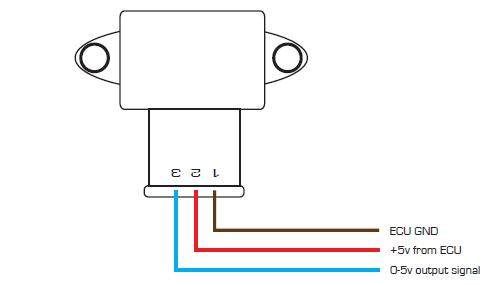
Accelerator pedal position sensor wiring diagram. September 30, 2020 - Circuit to detect open circuit faults on the VPA and VPA2 wires. Only VPA is shown for simplicity. ... Simulation result for the open-circuit detection circuit. ... Content may be subject to copyright. ... Fig. 1. Accelerator position sensor diagram and its connections to the ECU. The wiring harness on a vehicle seldom malfunctions unless the wires rub against something or an animal chews through the wires. The wiring harness for the throttle position sensor is contained in the main wiring harness and is well protected, except for the short part of the harness that leads from the main harness to the throttle position sensor --- its pigtail. Remove the accelerator pedal position sensor. Fig. APP sensor location ... Installation is the reverse of removal. ... Refer to the Electrical Wiring Diagram for component and connector locations, connector views, and circuit-specific information. The three wires (circuits) that feed Power, Ground and return a position signal (to APP Sensor 2) are: Circuit B, which is usually a Purple wire (ground). Circuit C, which is usually a Light Blue wire (APP Sensor 2 Signal). Circuit D, which is usually Tan wire (Power).
Nov 28, 2021 · Drive by wire technology is supported by the Elite 2500 ECUs and requires wiring of an Electronic Throttle and Accelerator Pedal Position sensor. Accelerator pedal position sensor wiring diagram wiring diagram is a simplified satisfactory pictorial representation of an electrical circuit it shows the components of the circuit as simplified shapes and the skill and signal links amongst the devices. Ford F-Series V10 6.8L Engine Sensor Location Guide. Oct 8, 2020 erwincsalarda. Ford F-Series V10 6.8L Engine Sensor Location Guide Accelerator Pedal Position Sensor Air Flow Meter/Sensor Air Temperature Sensor Ambient /…. Ford Car Sensors and Wiring Diagram Sensors and Wiring Diagram. In this example, the Accelerator Pedal Position (APP) sensor is of the potentiometer type. It receives two reference voltages from the Powertrain Control Module (PCM), having two ground wires and two signal wires that send a varying voltage back to the PCM relating to accelerator pedal position. The signal voltage sent back to the PCM may vary ... September 19, 2020 - Test the throttle position sensor in a few minutes using a digital multimeter.
The Accelerator Pedal Position sensor has two potentiometers that act to validate pedal position. But if there is a problem with one sensor the pedal should still work but you will have warning indicators on. If both are malfunctioning nothing will happen with the pedal. ... I attached the page out of the wiring diagrams and the APP connector view. Nov 23, 2021 · Cat Accelerator Pedal Position Sensor Wiring Diagram. November 23, 2021. January 13, 2022. · Cat 5. by tamble. If you are searching for Cat Accelerator Pedal Position Sensor Wiring Diagram, you are at the right site. We provide some wiring diagram for Cat 5. Download the diagram below: July 9, 2018 - E90 328 Throttle Pedal Wiring Diagram Trying to replace the Accel Pedal Sensor on my 01 Ex 7.3l to accomodate a tuner. The wiring harness for the tuner that is supposed to plug into accelerator sensor is a 10 wire single head and the accelerator on the Exc is a dual head accelerator with two smaller heads and only 5 wires combined.
Subaru P2138 — Ricks Free Auto Repair Advice Ricks Free Auto ...
Jun 12, 2021 · Accelerator pedal position sensor wiring diagram wiring diagram is a simplified satisfactory pictorial representation of an electrical circuit it shows the components of the circuit as simplified shapes and the skill and signal links amongst the devices. Based on this information the load requested by the driver can be implemented immediately.

TechDoc
September 28, 2020 - In some instances, the problem ... adjacent wires. If this is the case, replacing the defective wiring harness should solve the problem. ... Problem: The vehicle has an intermittent problem; the throttle valve occasionally fails to respond. The technician has detected a diagnostic trouble code, DTC P2138: Accelerator pedal position sensor D/E – Incorrect ...
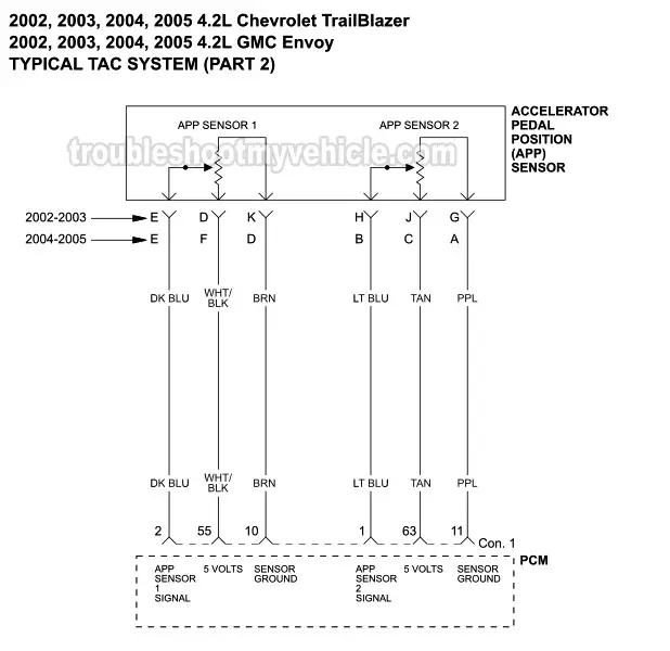
Part 1 -TAC System Wiring Diagram (2002-2005 4.2L Chevrolet ...
Here is a quick video on how to test a Throttle Position Sensor TPS with a multimeter. Also I show you how you can figure out what each wire on your sensor i...
Testing Accelerator Pedal Position Sensors (APS)
Accelerator Pedal Position Sensor Replacement Cost. The average accelerator pedal sensor replacement cost is between $100 and $300, depending on the car model and labor costs. The accelerator pedal sensor usually costs between $50 and $200. The labor cost can range from $50 to $100 at a workshop.
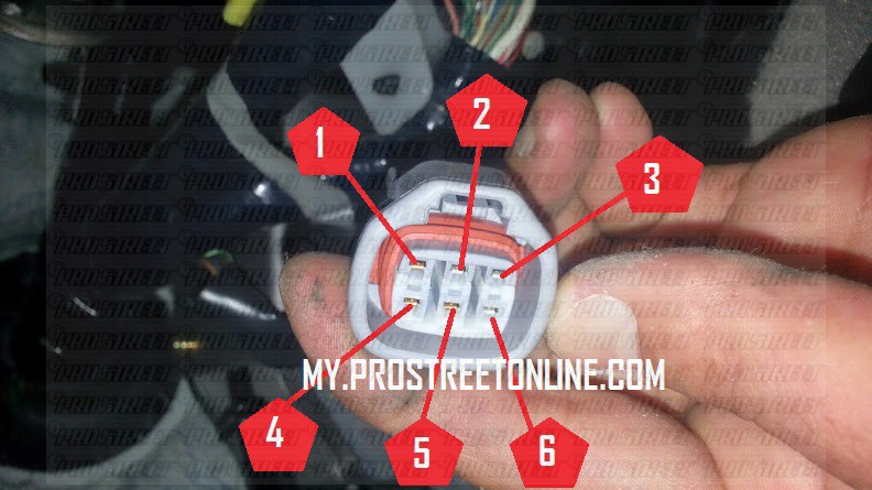
How To Test a VQ35 Accelerator Pedal - My Pro Street
Dec 21, 2021 · Tps Wiring Harness | Wiring Diagram – Accelerator Pedal Position Sensor Wiring Diagram In addition, Wiring Diagram provides you with time frame in which the assignments are to become accomplished. You’ll be in a position to understand specifically once the tasks ought to be completed, which makes it easier for you personally to effectively manage your time and effort.

GM Gen III LS PCM/ECM: Electronic Throttle Equipment Guide
DTC P0229: Throttle/Pedal Position Sensor/Switch 'C' Circuit Intermittent BAT Team Discussions for P0120 03 Silverado Battery not charging message Condition Some owners may comment that the Check Engine Light is illuminated and there is no driveability concern.

Throttle Position Sensor - Toyota Engine Control Systems
ABC Companies an exclusive U.S. Van Hool distributor is service-centered at every touchpoint in our organization!
Chrysler 300/300 Touring/300C, Dodge Magnum. Manual - part 1417
24/01/2019 · Accelerator Pedal Position Sensor Wiring Diagram – accelerator pedal position sensor circuit diagram, accelerator pedal position sensor wiring diagram, ford focus accelerator pedal position sensor wiring diagram, Every electric structure is composed of various distinct parts. Each component ought to be set and connected with different parts in …

Ford F250 super duty: On a 03 F250 w/ 7.3 diesel which wire
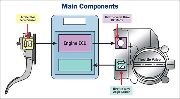
In modern throttle control systems, the throttle position sensor is used to detect the position of the throttle valve integrated into the actuator motor. A throttle position sensor or TPS is an accelerator pedal sensor without a pedal arm. Its electrical circuitry is the same as the accelerator pedal position sensor.
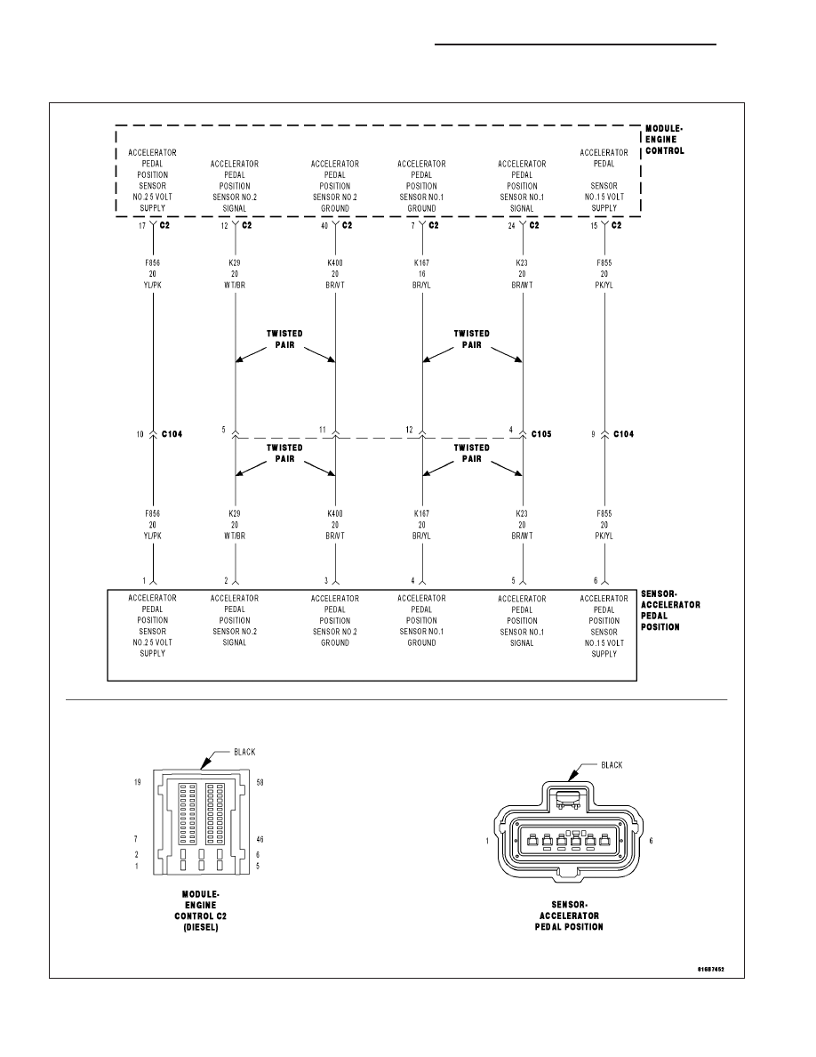
Dodge Ram Truck 1500-2500-3500. Manual - part 990
December 8, 2008 - C6 Tech/Performance - Accelerator pedal position (APP) sensor wiring diagram - Anyone help? - Hello everyone, I'm looking for a wiring diagram from a service manual for this sensor. It has 3 internal sensors to record pedal position and I need to know which wires are for which sensors for a ...
Toyota RAV4 Service Manual: Throttle / pedal position sensor ...
Accelerator pedal position sensor (main) ground: 77: Accelerator pedal position sensor (sub) 78: Power supply voltage applied to accelerator pedal position sensor (sub) 79: Accelerator pedal position sensor (sub) ground: 80: OBD pin7 connector (K-LINE) 81: ECM ground: 82: Power supply: 83: Throttle actuator control motor ground: 84: Throttle ...

Accelerator pedal position sensor - digital
Looking for some assistance for wiring the Bosch DBW throttle body, 60mm bore diameter and Bosch accelerator pedal to suit - for Haltech Elite 2500 ECU. From the Bosch website PDF it states the following, Pin 1 A Motor -. Pin 2 B Poti -. Pin 3 C Poti +. Pin 4 D Motor +.
1996-1998 Throttle Position Sensor Circuit Diagram (1.6L Civic)
Accelerator Pedal Released Position Learning is an operation to learn the fully released position of the accel- erator pedal by monitoring the accelerator pedal position sensor output signal. It must be performed each time harness connector of accelerator pedal position sensor or ECM is disconnected.
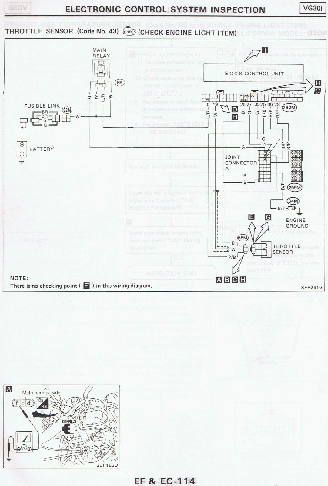
87 Pathfinder TPS wiring diagram - 86.5-89 WD21 Pathfinders ...
Throttle Position Sensor Wiring Diagram – dodge throttle position sensor wiring diagram, ford throttle position sensor wiring diagram, gm throttle position sensor wiring diagram, Every electric structure is composed of various different components. Each part ought to be placed and linked to different parts in particular manner. Otherwise, the arrangement won’t work as it ought to be.

Understanding the EFI Process - Page 6 of 7 - MotoIQ
Throttle Position Sensor Wire Diagram 4 | Manual E-Books – Throttle Position Sensor Wiring Diagram. Wiring Diagram comes with numerous easy to stick to Wiring Diagram Instructions. It is supposed to help all of the common user in building a suitable method. These guidelines will be easy to comprehend and implement.
Part 1 -Accelerator Pedal Position Sensor Basics (2007-2009 ...
Jan 24, 2019 · Tps Wiring Harness | Wiring Diagram – Accelerator Pedal Position Sensor Wiring Diagram In addition, Wiring Diagram provides you with time frame in which the assignments are to become accomplished. You’ll be in a position to understand specifically once the tasks ought to be completed, which makes it easier for you personally to effectively manage your time and effort.
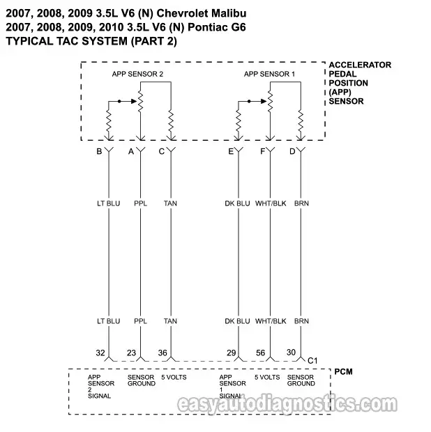
Throttle Body (TAC) Circuit Wiring Diagram (2007-2008 3.5L ...
Official Site of Painless Performance, American Made wiring harnesses for your hot rod, street rod, muscle car, off-road and everything in between. Wire it once and wire it right with Painless.

F super duty 7.3: Need a wiring diagram for the accelerator
• 0 V when the pedal is at the idle position. Ł B+ when the pedal is depressed The IVS receives a 12 V ignition voltage at Pin F from the ignition fuse in the power distribution box. When the pedal is not in the idle position (throttle applied), the IVS supplies a 12 V signal to the ECM.
I Have a P2127 Code, Throttle/ Pedal Position Sensor/switch E ...
Learn how to access vehicle repair guides and diagrams through AutoZone Rewards. Sign up today to access the guides.

Wiring Diagram ECU 2KD-FTV | Throttle | Systems Engineering ...
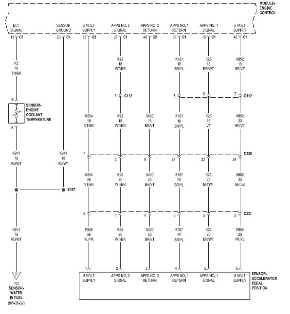
That the Accelerator Pedal Assembly is made up of 3 individual position sensors. Each one has separate signal, Ground, and 5.0 volt reference circuits. That APP Sensor 1's signal increases as the accelerator pedal is depressed, from below 1.1 volt at 0% pedal travel (pedal at rest) to above 2.1 Volts at 100% pedal travel (pedal fully depressed).

370Z Pedal Position Sensor pinout - G4+ - Link Engine ...
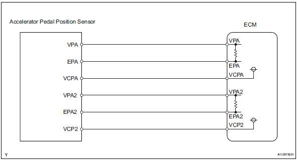
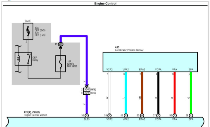
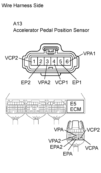
The accelerator pedal position sensor is mounted on the accelerator pedal to detect how much it is de-pressed. It has 2 sensor terminals (VPA and VPA2) to detect the accelerator pedal position and a malfunction ... WIRING DIAGRAM INSPECTION PROCEDURE 1 READ VALUE OF HAND-HELD TESTER(ACCEL POS #1 AND #2) (a) Connect the hand-held tester to ...
Can't find the TPS sensor on my 2005 | Dodge Cummins Diesel Forum
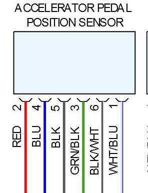
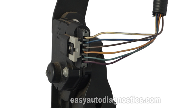
A dual contact type potentiometer APPS has six wires. So, a 6 pin accelerator pedal position sensor wiring diagram is, two wires are for the earth, two for the input voltage, and two for signals back to the computer (ECU). The non-contact-type accelerator pedal position sensor is of hall effect and inductive type.
Drive By Wire Throttle Wiring
Download scientific diagram | Wiring diagram of a forklift accelerator pedal circuit. from publication: Integrating Model-based Diagnosis Techniques into Current Work Processes - Three Case Studies from the INDIA Project. | Although the area of model-based diagnosis has developed a number of ...
Subaru Legacy Service Manual - Dtc p2135 throttle/pedal ...
mounted on the accelerator pedal. The accelerator pedal assembly is serviceable to the extent that the APS/IVS switch can be replaced without replacing the complete assembly. Accelerator Position Sensor (APS) The ECM sends a regulated 5V signal through the ECM black chassis connector terminal 3 to APS connector terminal C.

FOR THE WIRING DIAGRAM THROTTLE POSITION SENSOR PLUG, IT USE ...
Jun 2, 2020 - AGCO provides overall lowest costs of vehicle ownership. We do this by providing extremely high quality automotive service, following the theories and practices of Dr. W. Edwards Deming., electronic engine idle speed control

Infiniti G35 (V35). Manual - part 430
Jul 20, 2018 - The Chevrolet throttle position sensor has a high failure rate on certain year, makes and models. Review symptoms and diagnostic procedures of bad throttle position sensors.
2010 Toyota Yaris ACCELERATOR PEDAL WIRING HELP - Automotive ...
1 month ago - JavaScript is disabled. For a better experience, please enable JavaScript in your browser before proceeding · You are using an out of date browser. It may not display this or other websites correctly. You should upgrade or use an alternative browser · Car care advisers since 2003.

Wiring diagram of a forklift accelerator pedal circuit ...
Troubleshooting the pedal position sensor is gonna be difficult. omgwtfbbq!, Apr 10, 2018 #6. Apr 10, 2018 at 12:18 PM ... I would download the schematics/block diagrams for the accelerator sensor circuits and start testing. ... it's possible you did something to a wire or have a bad ground (did you disconnect your battery or anything in the ...

Dodge Caliber. Manual - part 878

Failsafe of Accelerator Pedal Position Sensor - Toyota Camry ...
DBW Pedal Wiring Questions - LS1TECH - Camaro and Firebird ...

Where do the pedal wires go? Gen IV - The 1947 - Present ...
Throttle position sensors

Nissan accelerator pedal position (APP) sensor - Erwin Salarda
this sucks! can't find wiring diagram for the accelerator ...
GSIC - Global Service Information Center

accelerator pedal position sensor wiring diagram toyota yaris ...
Kia Amanti Questions - Can anyone tell show me the wiring ...
0 Response to "38 accelerator pedal position sensor wiring diagram"
Post a Comment