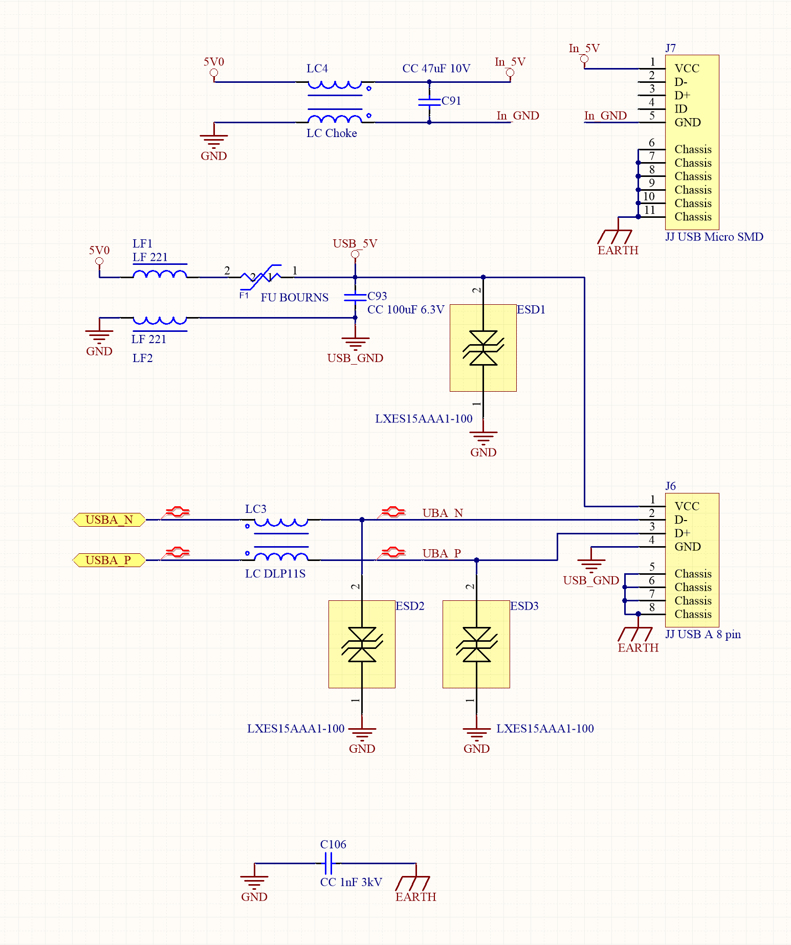
42 usb killer circuit diagram
Sep 01, 2020 · Universal Serial Bus (USB) is informally described in the Wikipedia article USB, and is formally defined by the standards published by the USB Implementers Forum, Inc. For convenience, we summarize the key USB concepts here, but the standards are the authoritative reference. Basic concepts and terminology computer as a USB Mass Storage Device, or act as a host if a memory card reader or a USB memory stick is connected. A USB capable EFM32 microcontroller can operate as a host, a device or as an OTG dual role device. EFM32 microcontrollers do not support operation as a USB hub. The EFM32 USB stack supports host mode and device mode, but not OTG mode.
View all results for thinkgeek. Search our huge selection of new and used video games at fantastic prices at GameStop.
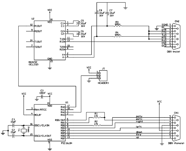
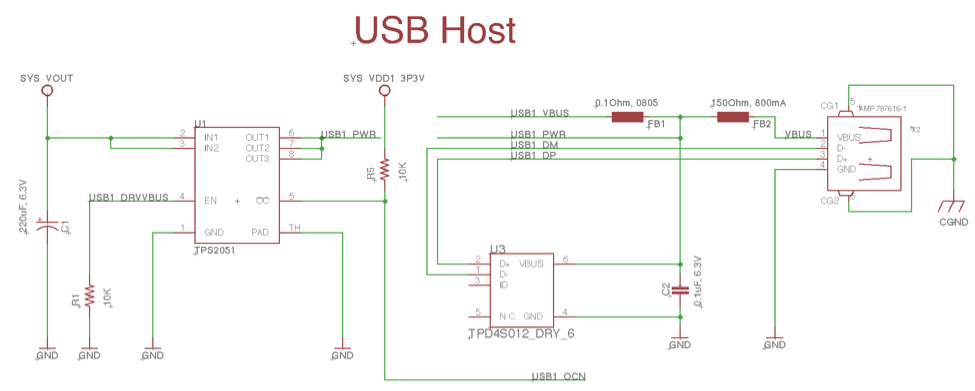
Usb killer circuit diagram
Mosquito Zapper Circuit Diagram and Theory of Operation. No matter how much effort you put into terminating their population, mosquitoes just keep growing in numbers. These tiny vampires are truly a nuisance, simply because they not only inflict painful itching over the bitten area but also have the potentials of spreading dreaded diseases like ... 4. Solder USB male jack to the Capacitor removed as shown in circuit and place in the USB case . 5. Apply electric tape for more safety. 6. Charge this USB by inserting into the female USB jack of Zapper circuit. Here USB Killer Completed. Note : Using of this USB killer will destroy your device , use it on your own risk. USB Standby Killer Circuit Diagram : This so-called 'USB-standby-killer' can be realised with just 5 components. The USB output voltage provides for the activation of the triac-opto driver (MOC3043) which has zero-crossing detection. This, in turn, drives the TRIAC, type BT126.
Usb killer circuit diagram. USB Standby Killer Circuit Diagram : This so-called 'USB-standby-killer' can be realised with just 5 components. The USB output voltage provides for the activation of the triac-opto driver (MOC3043) which has zero-crossing detection. This, in turn, drives the TRIAC, type BT126. USB Standby Killer Circuit Diagram : This so-called 'USB-standby-killer' can be realised with just 5 components. The USB output voltage provides for the activation of the triac-opto driver (MOC3043) which has zero-crossing detection. This, in turn, drives the TRIAC, type BT126. Mosquito Killer Circuit Diagram For USB Mosquito Killer Incense Stick. $8.00-$12.00 / Unidad. 1 Unidad (Orden mínima) CN Shenzhen Ibouk Electronics Technology Co., Ltd. Contactar proveedor. 1/5. Inversor de energía solar sin conexión a la red, 50hz, CC a CA, recargable, sinusoidal modificada con cargador de batería rápido de 15A, 1kw, 1,5 ... « usbkill » is an anti-forensic kill-switch that waits for a change on your USB ports and then immediately shuts down your computer. - GitHub - hephaest0s/usbkill: « usbkill » is an anti-forensic kill-switch that waits for a change on your USB ports and then immediately shuts down your computer.
USB killers consist of an few oscillators, a footstep upwards transformer together with a few capacitors. ... the circuit diagram of a basic killer circuit. The USB is a plug-and-play interface between the PC and the peripherals. USB is the short form of Universal Serial Bus, a standard port that helps to connect computer peripherals like scanner, printer, digital camera, flash drive and more to the Computer. The USB standard supports the data transfer at the rate of 12 Mbps. USB Standby Killer Circuit Diagram : This so-called 'USB-standby-killer' can be realised with just 5 components. The USB output voltage provides for the activation of the triac-opto driver (MOC3043) which has zero-crossing detection. This, in turn, drives the TRIAC, type BT126. Electronic mouse killer circuit diagram. Little To No Maintenance Required. ... Ad Keep Mice Out Of Your Kitchen Bathrooms Garage More. A boost convert from 5V USB up to 12 or 24V and get lots of experience with thatThen youll maybe not really have enough experience to safely work with 8000V and youll be knowledgeable enough to understand the.
USB Killer V3 [features, design, hardware specs] This amazing device can take energy (USB power source) from any device it's plugged into and to transfer that energy into its capacitor up to certain high voltage (~240V), destroying the whole system of the device.The host device will render useless during discharging process. A few years ago, [Dark Purple] built the USB equivalent of an RJ45 connector wired into mains power. The USB Killer is a simple device with just a FET, a few high voltage caps, a DC/DC converter ... USB Killer is a modified USB drive that destroys computers when you insert it into the machine's USB drive. There are different versions of this device, and you can even create a DIY version yourself for $3 or less. USB Killer is often used as an example of why you should refrain from plugging in unknown USB devices into your systems. Circuit diagrams for 418/433 MHz short-range communication (Elektor Electronics article) RF: Apr 12, 2014: 3: 88 - 108MHz FM audio transmitter / bug circuit diagram: Transmitters: Apr 12, 2014-1: Circuit diagram for superregenerative receiver built by GE labs: RF: Apr 12, 2014-3: X10 RF daughter board - receiver circuit diagram: RF: Apr 12, 2014: 0
The USBKill, or USB Killer is a device used by pentesters, industrial clients and law-enforcement world-wide to perform security checks against power surge attacks on USB ports. USBKill.com is manufacturer of the USB Kill device, USBKill Shield - which defends against USB Attacks like a USB Condom & other accessories
The SixtyClone is basically a reverse engineered replica of the orignal Commodore 64 motherboard PCB. The board is created to allow Commodore 64 computers that had damaged or faulty PCBs to be successfully repaired. This can be done by moving all components from an original motherboard to the replica board (or add in new parts as I have done).
Answer (1 of 4): Yes. However, I'm not going to do the google search to get the exact directions. I don't want to know how to make one specifically. I already know the theory, and that is scary enough. The fact that I could make one easily, without even following some directions is pretty bad. S...
These variants alond with USB wiring diagram are decided by the usb.org, which is a 'USB standards organization' that maintains USB standards and improvise the USB technology and its applications. i) micro a( USB 1.1 to 2): Previously in mobiles, now discontinued. ii) micro b( USB 1.1 to 2): All current mobiles/ laptops/ desktop PC.
What is a USB Killer ? How usb killer works ? Whats the purpous of it? Who invented USB Killer and why? I am going to answer all of your questions right now....
The USB Killer v2.0 is [Dark Purple]'s second version of this device. The first version was just a small board with a DC/DC converter, a few caps, and a FET. When plugged in to a computer, the ...
USB Standby Killer Circuit Diagram : This so-called 'USB-standby-killer' can be realised with just 5 components. The USB output voltage provides for the activation of the triac-opto driver (MOC3043) which has zero-crossing detection. This, in turn, drives the TRIAC, type BT126.
Push-Pull HF Active Antenna Circuit - DJ2LR. 88 MHz - 108 MHz FM-band Low Noise Amplifier. 1.3 GHz LNA. 7 MHz Multi-Q Preselector - DK2AG. 144MHz - 432 MHz LNA - DH7FB. High-IP3 Differential LNA - DL7VFS. Long Waves Preselector - DL6UU. 1296 MHz LNA - DJ1EE. 3-stages 1296 MHz LNA - DC0DA. 144 MHz & 432 MHz High Linearity LNA - DJ7VY
Dec 31, 2021 · Aurora R8, BSOD loop, can’t recover Dell Recovery disk or Ubuntu USB boot. Started by. MiraiKei 12-21-2021 Alienware Desktops. 0 Kudos 12 Replies 2532 Views. 0 ...
Re: USB KILLER V3 reverse engineering in progress UPDATED. The connection of the capacitors was actually wrong. They are connected according to this schematic. About the Voltage, the device is delivering pulses of 200V so there should be 100V per capacitor (2 capacitors in series in each branch but the last one).
Mar 10, 2015 — Within a week, I have developed quite specific circuit ... USB Killer Prototype ... Where can i find the schematics for this device?
Answer (1 of 5): Hi… The malicious USB thumb drive uses an inverting DC-to-DC converter to draw power from the computer's USB port in order to charge a capacitor bank to -110 Volts (negative voltage). The power is then sent back into the USB interface via a transistor and the process is repeated...
Build Your Own Deadly USB Killer To Take Down Any Device. DIY YouTuber Thomas Kim shows how to build a deadly USB killer to fry any computer or laptop. May be you heard about USB killer which fires an instant surge of power through your computer's motherboard when connected and fries your computer/laptop. But the device was priced around 49$.
USB Standby Killer Schematic Circuit Diagram. Admin October 20, 2018. 0 220 Less than a minute. When turning a computer on and off, various peripherals (such as printers, screen, scanner, etc.) often have to be turned on and off as well. By using the 5-V supply voltage from the USB interface on the PC, all these peripherals can easily be ...
Working principle of Mosquito Killer Bat explained in detail here. Mosquito Zapper Circuit explained here. Internal parts and circuit diagram of Mosquito Racket are explained. The Output Voltage of Mosquito Killer Bat is 600V-100V. And frequency is 100KHz - 200KHz.
Once the circuit is assembled and set up, the below shown design can be used for charging any spare Li-Ion Battery through the 5V Mobile Charger or USB port. First connect the battery across the indicated points, and then plug in the USB connector with your Mobile Charger or computer’s USB socket.
Universal Serial Bus (USB) is an industry standard that establishes specifications for cables, connectors and protocols for connection, communication and power supply (interfacing) between computers, peripherals and other computers. A broad variety of USB hardware exists, including 14 different connectors, of which USB-C is the most recent.
Jun 30, 2017 - How to Make an USB Killer: USB killer is a device which is ... How to Make an USB Killer Circuit Diagram, Usb, Technology, Diagram, Usb.
USB killers consist of anfew oscillators, a step up transformer and a few capacitors. At first the oscillator circuit takes 5-6 volts from the USB port when connected to a USB peripheral(for example USB port on your computer), and it drives the transformer which is step up function.
USB Standby Killer Circuit Diagram: This so-called 'USB-standby-killer' can be realised with just 5 components. The USB output voltage provides for the activation of the triac-opto driver (MOC3043) which has zero-crossing detection. This, in turn, drives the TRIAC, type BT126.
Battery Charger Circuit Diagram A battery charger, is a device used to put energy into a secondary cell or rechargeable battery by forcing an electric current through it. Now a Days so many rechargeable batteries are coming like 1.2 V, 3.7 v, 4v, 6v, 9v,12v,24v etc… you can check all types of battery charger circuit diagram at this page.
USB Standby Killer Circuit Diagram : This so-called 'USB-standby-killer' can be realised with just 5 components. The USB output voltage provides for the activation of the triac-opto driver (MOC3043) which has zero-crossing detection. This, in turn, drives the TRIAC, type BT126.
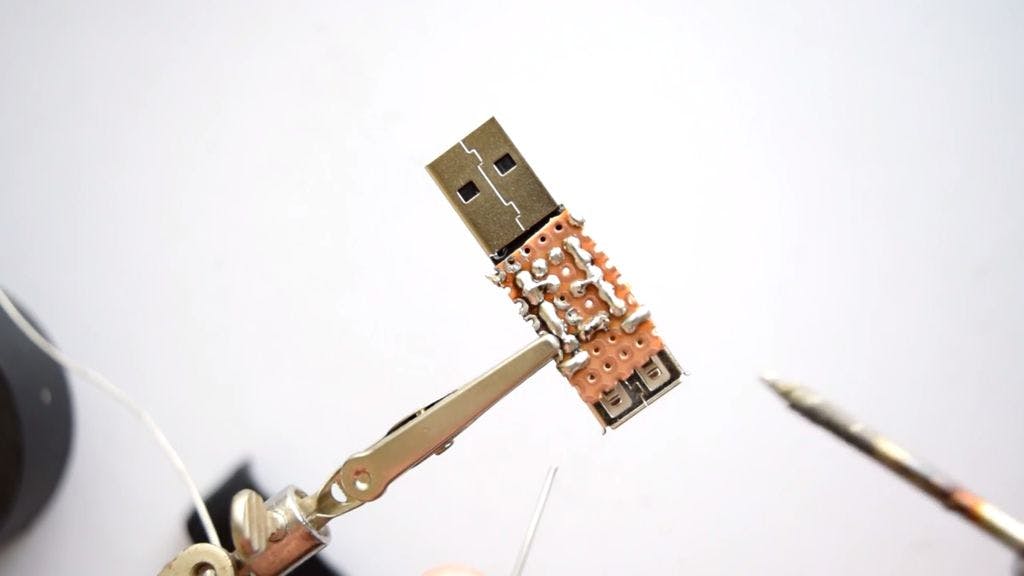
4. Solder USB male jack to the Capacitor removed as shown in circuit and place in the USB case . 5. Apply electric tape for more safety. 6. Charge this USB by inserting into the female USB jack of Zapper circuit. Here USB Killer Completed. Note : Using of this USB killer will destroy your device , use it on your own risk.
Mosquito Zapper Circuit Diagram and Theory of Operation. No matter how much effort you put into terminating their population, mosquitoes just keep growing in numbers. These tiny vampires are truly a nuisance, simply because they not only inflict painful itching over the bitten area but also have the potentials of spreading dreaded diseases like ...

When I was on the USCGC Polar Sea (WAGB-11) we went down to Antarctica on Operation Deep Freeze. Our mission was to break the ice and create a shipping lane for the fuel and cargo ship to resupply the base in McMurdo. While we were breaking ice these killer whales were following us looking for food. If you look at the top of the photo you can see some penguins on the sheet ice, that’s who they were looking for. I hope you enjoyed! I’m on IG @65_bomber Stop by and say hi!





0 Response to "42 usb killer circuit diagram"
Post a Comment