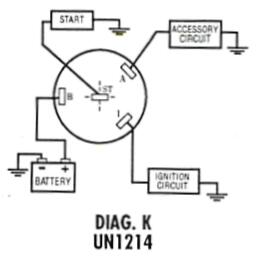
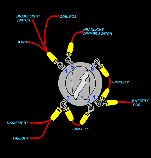
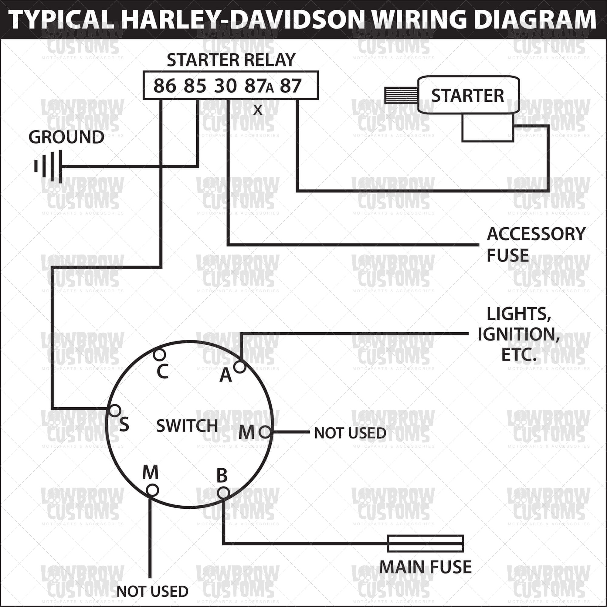
38 4 wire ignition switch diagram
Mar 27, 2016 · I replaced the switch and now the up doesn’t work at all. I believe I have deduced, that the wire that connects to the up (switch) is the problem. I am trying to find out the way to replace that wire. I can’t find a wire diagram for the boat and am not sure where that wire goes (connects to) other than the battery. Jul 30, 2015 — Kids Quads - 4 wire ignition diagram - I have one of those 90cc kids ... the wires came disconnected from the back of the ignition switch.
Connect the YELLOW wire to the yellow switch wire terminal and to the relay terminal labeled 85. Test the operation of the lamps as follows: Re-connect the battery. Turn on ignition switch and low beam headlamps for Fog Lamps, or high beam headlamps for Driving Lamps. Activate auxiliary lamp switch.
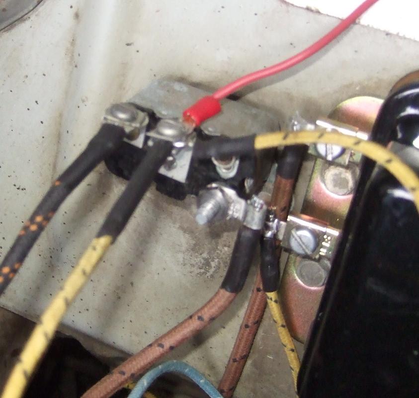
4 wire ignition switch diagram
Apr 04, 2018 · 4 Pin Ignition Switch Circuit Diagram. By Margaret Byrd | April 4, 2018. 0 Comment. Universal key switch 4 position mgi sdware wiring diagrams to help you understand how it is done electrical redsquare wheel horse forum an ignition infinitybox re lucas 162sa nas row land rover defender diagram allischalmers technical 12v flathead ford the h a m ... Oct 29, 2021 · A wiring diagram is a streamlined standard pictorial depiction of an electric circuit. 4 Wire Key Switch Diagram wiring diagram is a simplified agreeable pictorial representation of an electrical circuit. Amornsakco with 4 Wire Ignition Switch Diagram image size 540 X 711 px and to view image details please click the image. Apr 27, 2011 · The ignition control module (ICM) and the ignition coil get power (12 Volts). Power is supplied to the ignition coil thru' the wire labeled with the number 2.; The profile ignition pickup (PIP) sensor, which is what Ford calls the crank sensor, gets power from the ICM and as the engine cranks it starts to generate a crankshaft position signal (called the PIP signal).
4 wire ignition switch diagram. Jan 24, 2019 — Wiring an ignition switch is fast and easy with our Infinitybox system. See how to make the connections to the MASTERCELL. To test the ignition switch - Jim recommended simply running a temporary wire from Fuse #12 to the (+) terminal on the coil. Dave asked - Would I attach this "jumper" directly to the ignition switch? Is the attachment point obvious? Jim responded - The Black wire from the ignition switch goes to Fuse #11, 12. Feb 01, 2014 · Description : 4 Wire Ignition Switch Diagram in 4 Wire Ignition Switch Diagram, image size 600 X 630 px, and to view image details please click the image. Here is a picture gallery about 4 wire ignition switch diagram complete with the description of the image, please find the image you need. We hope this article can help in finding the ... 4 Wire Ignition Switch Diagram Atv 250cc Motorcycle, Moped Scooter, Kill Switch, Engine. S. Shaun Lyle. 2 followers. More information. 250cc Motorcycle.
Step 4: Disassemble The Steering Wheel — However, depending on the vehicle in question, you might need a push-button starter switch wiring diagram. Step 1: ... Fuse box diagram (fuse layout), location and assignment of fuses and relays Ford F150 / F-150 SVT Raptor / Ford Lobo (2009, 2010, 2011, 2012, 2013, 2014). Jul 7, 2015 — The two OEM wires I have left are the red and orange pictured. I've attached a wiring diagram for the new 4 wire ATV switch. Well. Aug 31, 2010 — Hey all I recently purchased a 4 wire ignition key switch to replace my main on/off switch on my 450f.... My question is what are the 4 ...
Trailer tow 7– and 4–pin connectors (parklamps) 11: 10: A/C compressor clutch relay, A/C compressor clutch solenoid, 4x4 Integrated Wheel Ends (IWE) solenoid: 12: 15: Fuel pump relay, Fuel pump shut-off switch, Fuel pump driver module, Fuel pump motor: 13: 10: Manual climate control mode switch, Rear window defroster relay coil, A/C ... To ignition system To starter motor solenoid To accessories e.g. radio, lights, cigar sockets etc. IGNITION SWITCH Brass terminals on switch Wiring Diagram For 4 Position Universal Ignition Switch Product Code P00940 Dec 25, 2017 · 4 Wires Ignition Switch For Gas Scooter Mini Choppers Online. Universal Motorcycle Ignition Switch Motor Bike 4 Wires With 2 Keys Banggood Com Sold Out Arrival Notice. Peugeot Sdfight Ignition Wiring Diagram 128 Solution. 4 Wire Black Ignition Key Switch On Style Ver 2 For Kid Electric Scooter Com. Nov 09, 2021 · 4 Wire Ignition Switch Diagram Atv In 2021 Atv 50cc Atv Diagram . 15 Car Start Button Wiring Diagram Car Diagram Wiringg Net Diagram Outlet Wiring Keyless Entry Car .
Apr 27, 2011 · The ignition control module (ICM) and the ignition coil get power (12 Volts). Power is supplied to the ignition coil thru' the wire labeled with the number 2.; The profile ignition pickup (PIP) sensor, which is what Ford calls the crank sensor, gets power from the ICM and as the engine cranks it starts to generate a crankshaft position signal (called the PIP signal).
Oct 29, 2021 · A wiring diagram is a streamlined standard pictorial depiction of an electric circuit. 4 Wire Key Switch Diagram wiring diagram is a simplified agreeable pictorial representation of an electrical circuit. Amornsakco with 4 Wire Ignition Switch Diagram image size 540 X 711 px and to view image details please click the image.
Apr 04, 2018 · 4 Pin Ignition Switch Circuit Diagram. By Margaret Byrd | April 4, 2018. 0 Comment. Universal key switch 4 position mgi sdware wiring diagrams to help you understand how it is done electrical redsquare wheel horse forum an ignition infinitybox re lucas 162sa nas row land rover defender diagram allischalmers technical 12v flathead ford the h a m ...











![[DIAGRAM] Wiring Diagram For The Pollak Heavy Wiring Diagram FULL Version HD Quality Wiring ...](https://static-cdn.imageservice.cloud/4385145/boat-kill-switch-diagram-best-of-pollak-ignition-wiring-diagram.jpg)
0 Response to "38 4 wire ignition switch diagram"
Post a Comment