37 Draw The Shear Diagram For 0 ≤ X ≤ 14 Ft Of The Compound Beam.
PDF Example 6 - Etu Draw the shear and moment diagrams for the beam shown in Fig. 6-7a. (a) L w 0 w —— 2 0 L (b) 2- L 3 w —— 2 0 L — 3 w 0 L2 w 0 Solution Support Reactions.The distributed load is replaced by its resultant force and the reactions have been determined as shown in Fig. 6-7b. Shear and Moment Functions.A free-body diagram of a beam ... (PDF) Shear Forces and Bending Moments - Academia.edu Assume that the soil pressure on the underside of the beam is A D uniformly distributed with intensity q2. (a) Find the shear force VB and bending moment MB at point B. q2 (b) Find the shear force Vm and bending moment Mm at the midpoint 3.0 ft 8.0 ft 3.0 ft of the beam. Solution 4.3-13 Foundation beam q1 = 3500 lb/ft (b) V and M at midpoint E ...
40 draw the shear diagram for the shaft. Draw The Shear Diagram For 0 X 14 Ft Of The Compound Beam ... a) Calculate the shear force and bending moment for the beam subjected to a concentrated load as shown in the figure. Then, draw the shear force diagram (SFD) and bending moment diagram (BMD). b) If P = 20 kN and L = 6 m, draw the SFD and BMD for the beam. P kN L/2 L/2 A B EXAMPLE 4
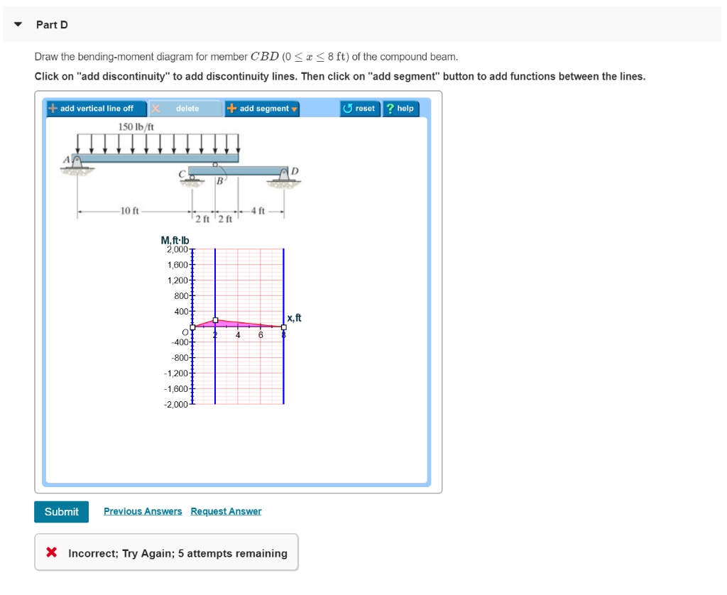
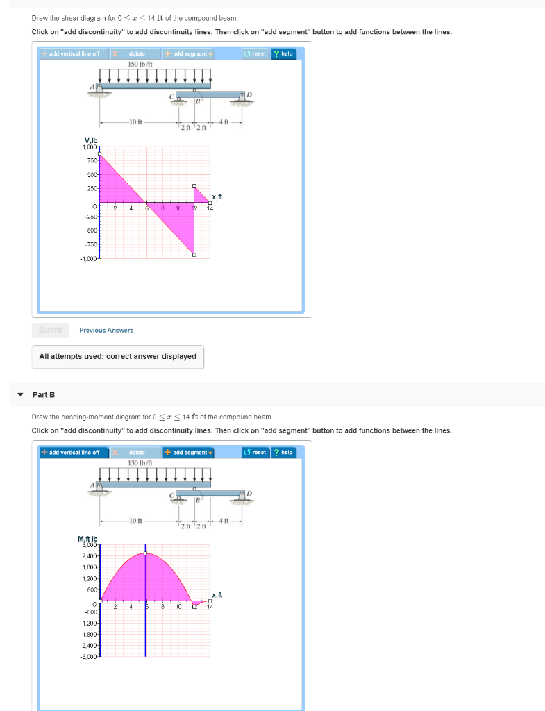
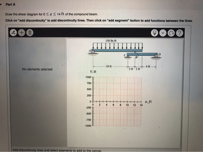
Draw the shear diagram for 0 ≤ x ≤ 14 ft of the compound beam.
Beam Stress & Deflection | MechaniCalc The maximum shear stress occurs at the neutral axis of the beam and is calculated by: where A = b·h is the area of the cross section. We can see from the previous equation that the maximum shear stress in the cross section is 50% higher than the average stress V/A . Shear Stresses in Circular Sections The beam AB shown in the figure supports a uniform load of ... The hinge can transmit a shear force but not a bending moment. A force P acts upward at A and a uniform load of intensity q acts downward on beam DE. Draw the shear-force and bending-moment diagrams for this compound beam. Solution 4.5-27 Compound beam A E B P C D 2 L L L L q A V M E B P C D 2 L L L L q PL D D P − P − qL − qL 2 -qL L L ... Solved Part ADraw the shear diagram for 0 ≤ x ≤ 14 ft of ... Part A. Draw the shear diagram for 0 ≤ x ≤ 14 ft of the compound beam. Part B. Draw the bending-moment diagram for 0 ≤ x ≤ 14 ft of the compound beam. Part C. Draw the shear diagram for member CBD (0 ≤ x ≤ 8 ft) of the compound beam. Part D.
Draw the shear diagram for 0 ≤ x ≤ 14 ft of the compound beam.. Ch06 07 pure bending & transverse shear - SlideShare Draw the shear and moment diagrams for the beam. 2 m 3 m 10 kN 8 kN 15 kNиm 6-6. Draw the shear and moment diagrams for the overhang beam. A B C 4 m 2 m 8 kN/m 6-7. Draw the shear and moment diagrams for the compound beam which is pin connected at B. 4 ft 6 kip 8 kip A C B 6 ft 4 ft 4 ft 06 Solutions 46060_Part1 5/27/10 3:51 PM Page 331 5. PDF Hibbeler Chapter 6 Part 1 (463-486) - Auburn University Draw the shear and moment diagrams for the shaft. The bearings at Aand Dexert only vertical reaction on the shaft.The loading is applied to the pulleys at Band Cand E. A B 14 in. 20 in. 15 in. 12 in. 80 lb 110 lb 35 lb C D E Ans: M(lb in) A simple endocrine pathway will include which of the ... A simple endocrine pathway is a negative feedback in which is primary aim is to reduce the initial stimulus and restore the pre-existing state or promote homeostasis.This system responds directly by secreting hormone to the stimulus. Thus a simple endocrine pathway will include the following: Classic hormone Target tissue Sensor Endocrine organ Draw the shear force and bending moment diagrams for beam ... (a) Determine the distance x that will produce the maximum shear force in the beam, and also determine the maximum shear force V max (b) Determine the distance x that will produce the maximum bending moment in the beam, and also draw the corresponding bending- moment diagram. (Assume P H11005 10 kN, d H11005 2.4 m, and L H11005 12 m.)
Which of the following accounts is classified differently ... 1 Answer Notes payable is different than the rest. That is a liability, while the rest are all assets. Maybe you like Titan quest immortal throne cd key? How much work does the electric field do in moving a proton from a point with a potential of 129 V to a point? Draw the shear diagram for 0 ≤ x ≤ 14 ft of the compound beam. (PDF) Mechanics of materials solution manual - Academia.edu mechanics of materials solution manual. Chapter# 6-14. Enter the email address you signed up with and we'll email you a reset link. Draw the shear diagram for 0 ≤ x ≤ 14 ft of the compound beam. Calculate the shear force at point B by substituting for x in equation (1). Calculate the bending moment at point A by substituting 0 for x in equation (2). Calculate the bending moment at point B by substituting for x in equation (2). Consider a section between segment BD of the beam and draw its free body diagram. PDF P5.2. Write the equations for shear and moment B between ... For each beam, draw the shear and moment curves label the maximum values of shear and moment, locate points of inflection, ... Orgin @ A, Range 0 ≤ x, ‒ 15 ... Shear and Moment Diagram The beam shown is pin supported at point A; roller supported at points B, D, and F
PDF HW 10 SOLUTIONS - University of Utah 0-81. Draw the shear and moment diagrams for the 3Œzs-ib wnnn,. 20001b SOO .7—85. The beam will fail when the maximum moment 30 kip • ft or the maximum shear is V 8 kip. max max Determine the largest intensity w of the distributed load the beam will support. = 4w; 6 ft 6 ft Thus, w = 2 kip/ft -30= -6w w = 5 kip/ft 2 kip/ft Ans . Author ... 7.79 draw the shear diagram for the beam. From moment equilibrium, X M A = 0 = M-1 2 Pl + Pl or M =-1 Draw the shear diagram for 0 ≤ x ≤ 14 ft of the compound beam. 7-51 Complete Problem 7-51 from your Hibbeler textbook with all of the following modifications: (A) Replace the support reactions (pin at A and roller at B) with a single fixed support at point A (B) Determine the -1375 ... MEM 330 1st Mid-term Solutions.pdf - 1. A compound beam ... A compound beam, consisting of a 4-ft long section ABC and a 2-ft long section CD that are connected at C by a. ... Use the free-body diagram method to derive the shear force and bending moment equations of the entire beam. Section AB: 0 ≤ ࠵? ≤ 2 ft ࠵? ... Draw the shear force and bending moment diagrams. Ma il Terzo Reich??Come si pronuncia?? Draw the shear diagram for 0 ≤ x ≤ 14 ft of the compound beam. Ma pensate veramente che idolare una fazione politica possa dare un senso alla vostra vita? Hottest videos. Leave a Reply Cancel reply. Your email address will not be published. Required fields are marked * Comment *
Solved: Draw the shear diagram for 0 ? z ? 14 ft of the c
The hinge can transmit a shear force but not a bending ... The hinge can transmit a shear force but not a bending moment. The loads on the beam consist of a 4-kN force at the end of a bracket attached at point B and a 2-kN force at the midpoint of beam DE Draw the shear-force and bending-moment diagrams for this compound beam. A E B C D 4 kN 1 m 2 kN 1 m .

Draw the shear and moment diagrams for the compound beam ...
How to draw shear and moment diagrams - Quora Answer: First you need to calculate reaction forces and moments using equilibrium equations. Then you can proceed to next step. Divide your beam into several parts (dimensions in the picture can give you a hint) and draw arrow with x_{n} symbol for each of n parts. Now go from one side (for examp...
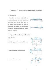
Mechanics of Materials Chapter 4 Shear and Moment In Beams
PDF Shear Forces and Bending Moments ≤ P ©F VERT 0: ©M A 0: R B P ¢1 2b L P P ≤ (downward) b L b AB R A RB P b L/2 AC A V M Problem 4.3-4 Calculate the shear force V and bending moment M at a cross section located 0.5 m from the fixed support of the cantilever beam AB shown in the figure. Solution 4.3-4 Cantilever beam A B 4.0 kN 1.5 kN/m 1.0 m 1.0 m 2.0 m Free-body diagram ...

Determine the normal, shear force, and bending moment at C and D
PDF Chapter 4 Shear and Moment In Beams - ncyu.edu.tw (1) Derive the shear and bending moment equations. And (2) draw the shear force and bending moment diagrams. Neglect the weight of the beam. The support reactions A and C have been computed, and their values are shown in Fig. (a). Solution Part 1 Due to the presence of the coupleC 0,We must analyze segments ABand BC separately.
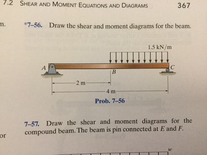
Solved *7-56, Draw the shear and moment diagrams for the ...
How do you get the ability leaf bracer in kingdom hearts ... Are they any history related words that start with the letter x? Smile, your mom chose life? What is this Ionic Compound Cr(CIO3)2? Draw the shear diagram for 0 ≤ x ≤ 14 ft of the compound beam. Hottest videos. Leave a Reply Cancel reply. Your email address will not be published.
Mechanics of Materials Chapter 4 Shear and Moment In Beams
PDF Chapter 2. Design of Beams - Flexure and Shear CE 405: Design of Steel Structures - Prof. Dr. A. Varma • In Figure 4, My is the moment corresponding to first yield and Mp is the plastic moment capacity of the cross-section. - The ratio of Mp to My is called as the shape factor f for the section. - For a rectangular section, f is equal to 1.5. For a wide-flange section, f is equal to 1.1. ...
Chapter 7, Internal Forces Video Solutions, Engineering ...
Assignment Solutions-Set 01 - *6-4. Express the shear and ... The subject matter is organized into 14 chapters. Chapter 1 begins with a review of the important concepts of statics, followed by a formal definition of both ... we refer to the fr ee-body diagram of the beam segment . ... Express the shear and moment in terms of x for . 0 6 x 6 3 m. and . 3 m 6 x 6 4.5 m, and then draw the shear and moment ...
SOLUTION
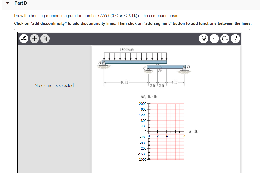
Solved Part ADraw the shear diagram for 0 ≤ x ≤ 14 ft of ... Part A. Draw the shear diagram for 0 ≤ x ≤ 14 ft of the compound beam. Part B. Draw the bending-moment diagram for 0 ≤ x ≤ 14 ft of the compound beam. Part C. Draw the shear diagram for member CBD (0 ≤ x ≤ 8 ft) of the compound beam. Part D.

Drawing Shear and Moment Diagrams for Beam
The beam AB shown in the figure supports a uniform load of ... The hinge can transmit a shear force but not a bending moment. A force P acts upward at A and a uniform load of intensity q acts downward on beam DE. Draw the shear-force and bending-moment diagrams for this compound beam. Solution 4.5-27 Compound beam A E B P C D 2 L L L L q A V M E B P C D 2 L L L L q PL D D P − P − qL − qL 2 -qL L L ...
329 6–1. Draw the shear and moment diagrams for the shaft ...
Beam Stress & Deflection | MechaniCalc The maximum shear stress occurs at the neutral axis of the beam and is calculated by: where A = b·h is the area of the cross section. We can see from the previous equation that the maximum shear stress in the cross section is 50% higher than the average stress V/A . Shear Stresses in Circular Sections
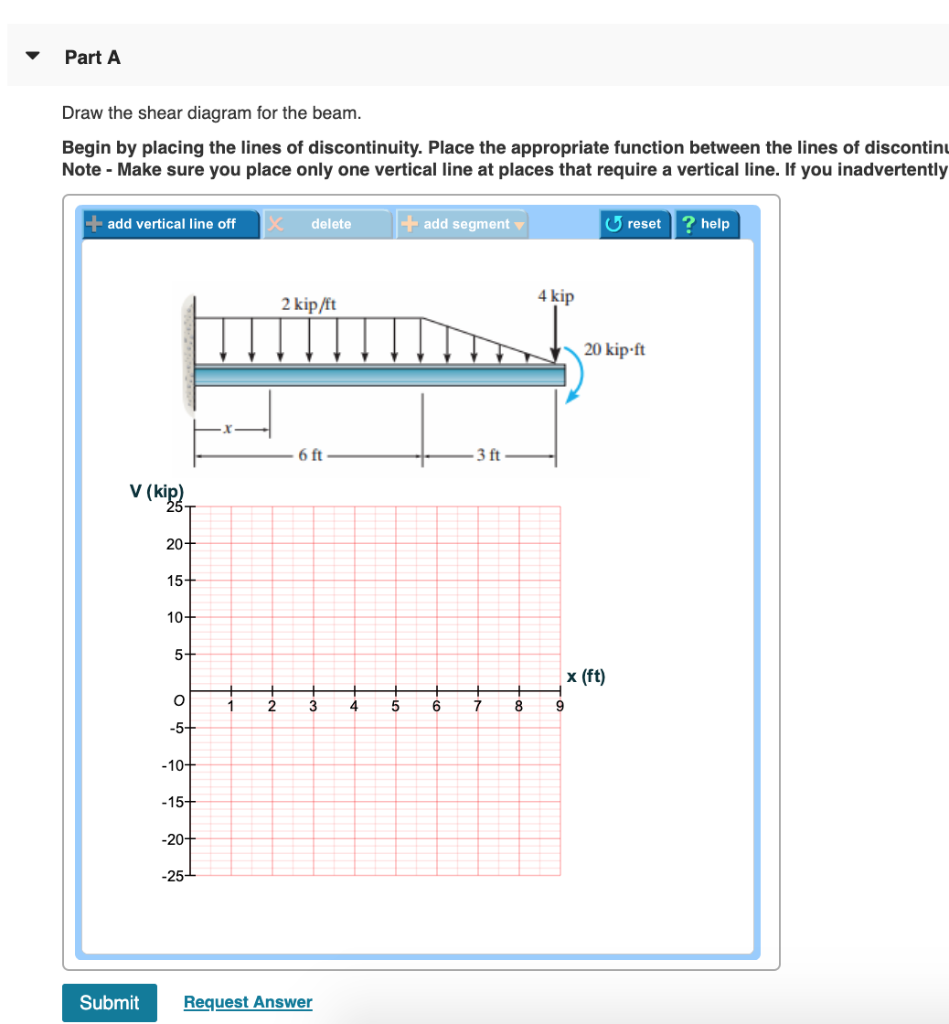
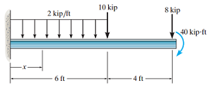
Solved Problem 6.8 17 of 51> Review 2 kip/It 4 kip 20 kip-ft ...

Draw the shear diagram for 0 ≤ x ≤ 14 ft of the compound beam.
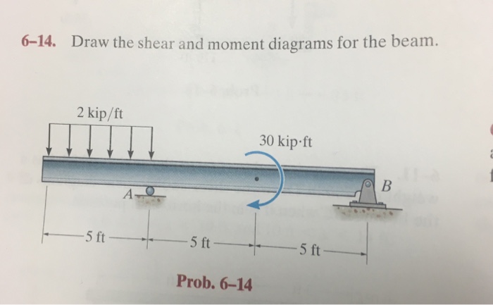
Solved) - 6-14. Draw the shear and moment diagrams for the ...
329 6–1. Draw the shear and moment diagrams for the shaft ...

4. Draw the shear and moment diagrams for the compound beam ...

Drawing Shear and Moment Diagrams for Beam - YouTube
Solved a) Draw the shear diagram for the beam. b) Draw ...
SOLUTION
ch4
329 6–1. Draw the shear and moment diagrams for the shaft ...

PDF) Statics Note, Statics (Solution and Answer) | Syuqeri ...

a. Draw a complete free-body diagram for the beam shown in ...
329 6–1. Draw the shear and moment diagrams for the shaft ...
329 6–1. Draw the shear and moment diagrams for the shaft ...
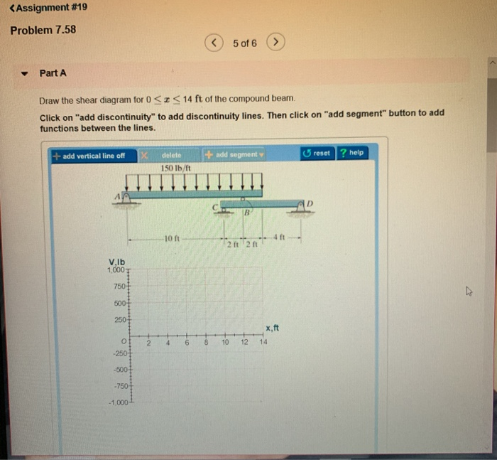
Solved Assignment #19 Problem 7.58 5 of 6> PartA Draw the ...

Draw the shear diagram for 0 ≤ x ≤ 14 ft of the compound beam.
Mechanics of Materials Chapter 4 Shear and Moment In Beams
Solved Draw the shear diagram for 0 14 ft of the compound ...
Solved Part A Draw the shear diagram for 0

PDF) Shear Forces and Bending Moments | Md. Shahin Alam ...
Hibbeler R.C. Structural Analysis

Draw the shear diagram for 0 ≤ x ≤ 14 ft of the compound beam.

4. Draw the shear and moment diagrams for the compound beam ...
Shear Forces and Bending Moments
Solutions Mannual statics bedfort second section

Statics 7.61 - Draw the shear and moment diagrams for the beam.
Solved Part A Draw the shear diagram for 0 <14 ft of the ...
0 Response to "37 Draw The Shear Diagram For 0 ≤ X ≤ 14 Ft Of The Compound Beam."
Post a Comment