39 4 Wire Transmitter Wiring Diagram
Trying To Find a 4 Wire Pressure Transducer | Automation ... A 4-wire transmitter is usually noted as having a separate power (i.e. plus and minus) supply and an a separate analog output (i.e. plus and minus). I work with all of these all of the time. What I understand you're describing to me is either a 2-wire (4-20 Ma) or a 3-wire voltage transmitter. Difference between 2 wire & 4 wire transmitter current ... Here, the transmitter is not really a current source in the sense that a 4-wire transmitter is. Instead, a 2-wire transmitter's circuitry is designed to act as a current regulator, limiting current in the series loop to a value representing the process measurement, while relying on a remote source of power to motivate current to flow.
4 Wire Transmitter Wiring Diagram - Free Wiring Diagram Nov 19, 2021 · 4 Wire Transmitter Wiring Diagram. November 19, 2021 by Larry A. Wellborn. Assortment of 4 wire transmitter wiring diagram. A wiring diagram is a streamlined standard photographic representation of an electrical circuit. It shows the components of the circuit as streamlined shapes, and also the power as well as signal links between the tools.
4 wire transmitter wiring diagram
PDF 2-Wire & 4-Wire Transmitter Wiring Dia gra ms 2-Wire & 4-Wire Transmitter Wiring Dia gra ms Transmitter 4 - Wire Transmitter 4 - Wire 25 mA Common 25 mA 25 mA Common 25 mA 25 mA Common 25 mA 25 mA Common 7 7 6 5 4 3 2 Output 4-20mA 1 Output 4-20mA 120Vac power ... 4-Wire Transmitter P.O. Box 847 R-Safe Specialty Newman, CA 95360 Tel: 209-862-0230 Toll-free: 1-800-860-3088 Fax: 209-862-0380 ... 4 wire transmitter on 2 wire Analog Input module - Entries ... Joined: 3/28/2010. Last visit: 2/11/2022. Posts: 774. Rating: (174) From the wiring connection diagram in the AI manual, I think Siemens means that a 2 wire input is for an active output from a field device which derives its power from the field device. What are 2-Wire and 4-Wire Transmitter Output Loops ... C'mon over to where you can learn PLC programming faster and easier than you ever thought possible!===== Chec...
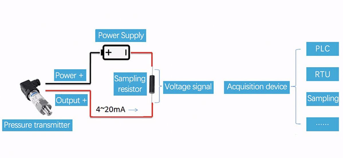
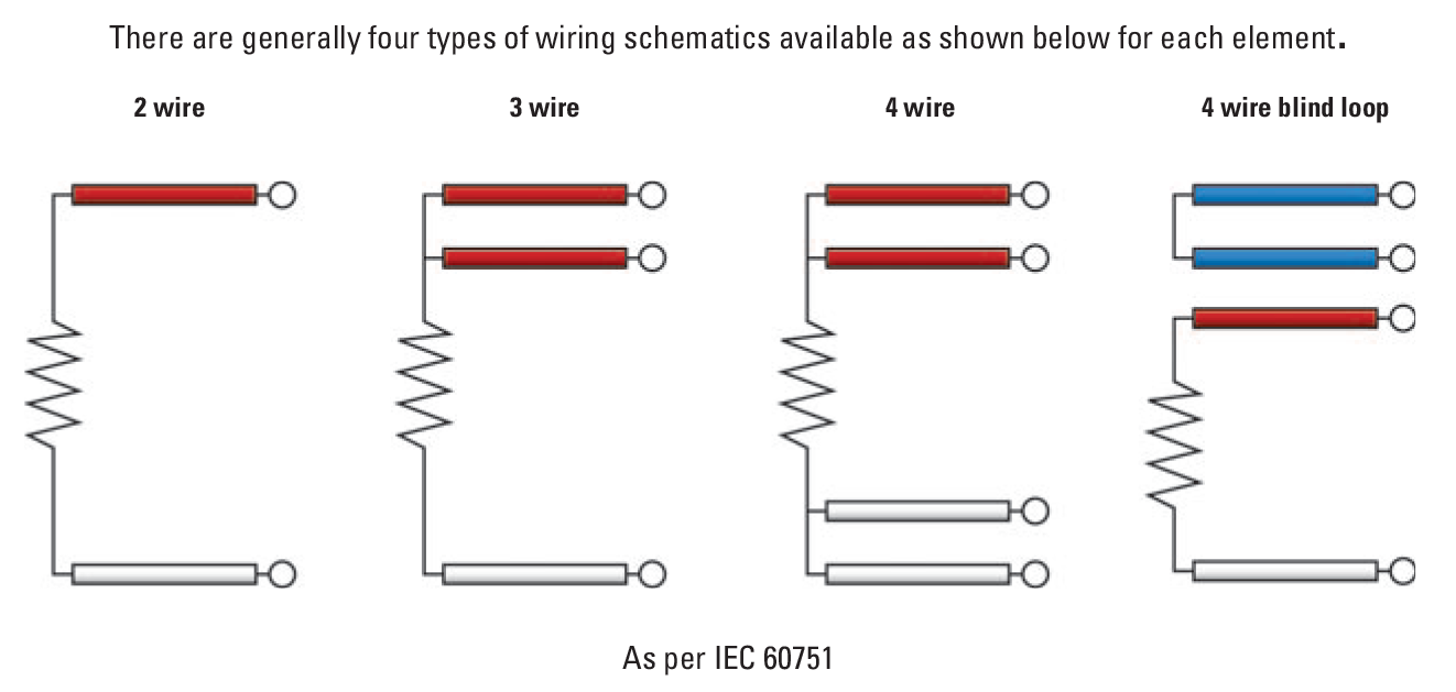
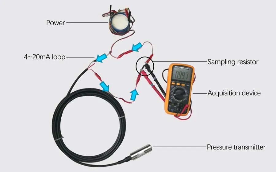
4 wire transmitter wiring diagram. Pt100 Wiring for your industrial temperature sensors ... Pt100 Temperature Sensor Wiring Diagram. 3 wire Pt100 RTD Sensor Wiring System. The addition of a third wire, connected to one side of the measuring element, helps to compensate for the lead resistance. It is very important that each of the three wires used in the measuring circuit are equal in terms of both conductor size and length. PDF RTD Wiring Diagrams - Tempco tial leads. 4-wire circuits may be usable over a longer distance than 3-wire, but you should consider using a transmitter in electrically noisy environments. R1 L1 RT R2 R3 L2 L1 Es Eo R1 RT R2 R3 L2 Es L1 RT RT RT L4 L3 L2 Is Eo Wiring Diagrams PDF Rosemount 3144P Temperature Transmitters with FOUNDATION ... 8. Install field wiring conduit into the open transmitter conduit entry (for remote mounting) and feed wires into the transmitter housing. 9. Pull the field wiring leads into the terminal side of the housing. 10. Attach the sensor leads to the transmitter sensor terminals. The wiring diagram is located inside the housing cover. 11. 4-20ma Pressure Transmitter Wiring - Micro Sensor Figure 1. It is a typical usage of two-wire 4-20mA pressure transmitters for most customers showed in figure 1. After the pressure transmitter is powered on, the loop current is proportional to the pressure to generate a 4-20 mA signal by collecting the pressure. The current flow through the sampling resistor (typical 100 Ω, 250 Ω) which ...
Wiring diagrams for HART devices and the Field ... Connect to a 4-wire HART transmitter If you have a 250 Ohm resistor, you can insert it in between the device terminals and connect the lead set across the resistor. Otherwise, you can enable the internal resistor in the device connection wizard. Pt100 in 2-, 3- or 4-wire connection? - WIKA blog A further possibility to substantially decrease the influence of the cabling is to increase the conductor cross-section. With a cross-section of 0.5 mm 2 the line resistance is only 0.036 Ω/m or 0.1 °C/m. Both options (3/4-wire connection or increasing the cross-section) lead to a higher cost in the cabling, which can be problematic, especially in cost-sensitive markets such as machine building. 2, 3, and 4 Wire RTDs: What is the Difference? RTD wiring configurations There are three types of wire configurations, 2 wire, 3 wire, and 4 wire, that are commonly used in RTD sensing circuits. A 2-wire configuration with a compensating loop is also an option. 2 wire RTD connections The 2 wire RTD configuration is the simplest among RTD circuit designs. Loop Powered Transmitter Wiring Diagram Wiring Diagram 4 Wire Og Signal plete Wiring Schemas. The best complementary is always to use a verified and accurate Loop Powered Transmitter Wiring Diagram that's provided from a trusted source. A good, traditional company that has a long track cassette of providing the most up-to-date wiring diagrams easy to use is not difficult to find.
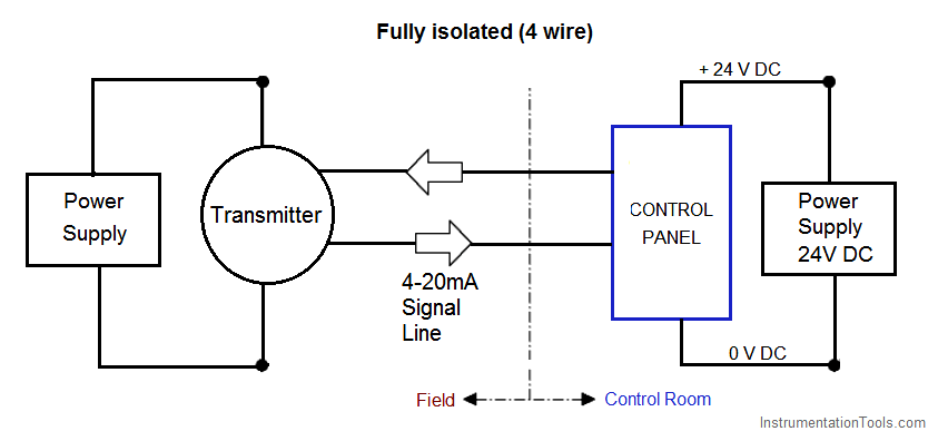
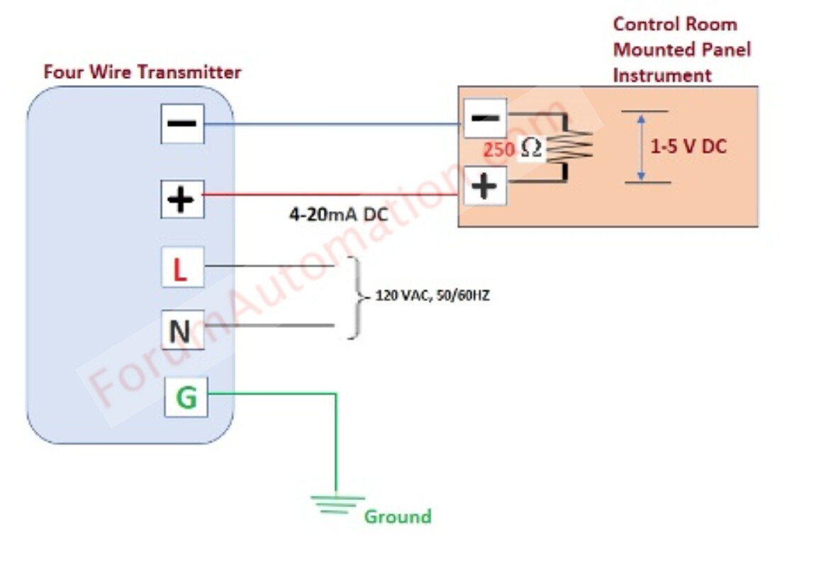
PDF Introduction to the Two-Wire Transmitter and the 4-20mA ... Tel 248-295-0880 Fax 248-624-9234 sales@acromag.com 30765 Wixom Rd, Wixom, MI 48393 USA INTRODUCTION TO THE TWO-WIRE TRANSMITTER AND THE 4-20MA CURRENT LOOP 6 3. Transmitter: This is the device used to transmit data from a sensor over the two-wire current loop. There can be only one Transmitter output in any 4 - 20mA Transmitter Wiring Types: 2 -Wire, 3 - Wire & 4 ... The 4 mA zero-end current is sufficient to drive the internal circuitry of the transmitter and the current from 4 to 20 mA represents the range of the measured process variable. The power supply and the instruments are usually mounted in the control room. The schematic diagram below shows the wire transmitter configuration: Example 4-20mA thermistor transmitter wiring diagram ... Example 4-20mA thermistor transmitter wiring diagram. So when the ROI-XMA Thermistor transmitter is used with the ROI-USB current measurement A-D, the PC can be used to measure a Thermistor with higher precision than a direct measurement system. The 4-20mA transmitter gain can be adjusted. This can minimize the span of the temperature sensor range. Planet Analog - 4-Wire Current-Loop Sensor Transmitters 4-wire sensor transmitter simplified block diagram. Unlike the 2- and 3-wire transmitter representations shown in Figure 2, the 4-wire circuit has separate paths for the power current and signal current. Also, the 4-wire receiver does not share a common return (GND) with the power supply. This allows for several new isolation schemes, including ...
What is the difference between two wire and four wire ...
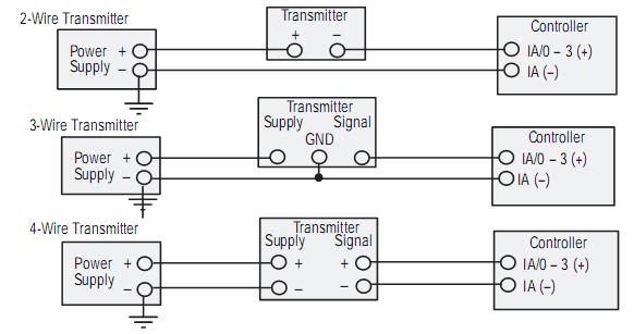
What are 2-wire and 4-wire Transmitter Output Loops ... May 25, 2020 · – The actual wiring between the transmitter and the power supply depends upon whether it is a 2-wire or a 4-wire type. – A 4-wire transmitter has 2 wires connected to a power supply, and 2 signal wires connected to the PLC. – A 2-wire transmitter has only 2 wires and is connected in series with the power supply and the PLC.

What are 2-wire and 4-wire Transmitter Output Loops? - RealPars
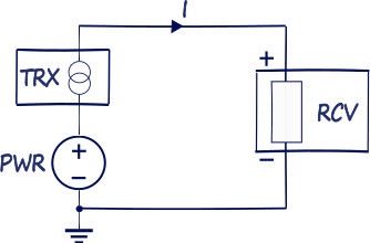
4-wire Transmitters Current Loops - InstrumentationTools The simplest form of 4-20 mA measurement loop is one where the transmitter has two terminals for the 4-20 mA signal wires to connect, and two more terminals where a power source connects. These transmitters are called “4-wire” or “self-powered” units. The current signal from the transmitter connects to the process variable input terminals of the controller to complete the loop:
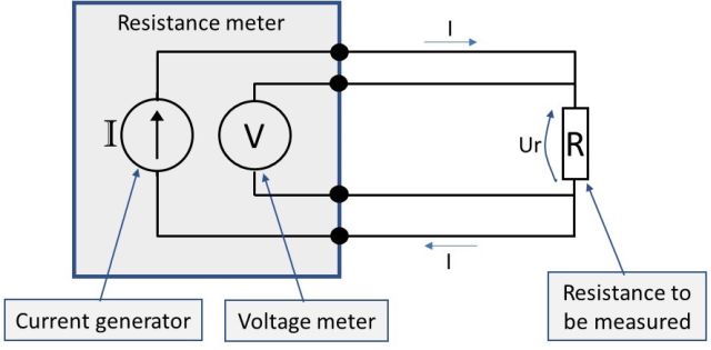
Resistance measurement; 2, 3 or 4 wire connection – How does ...
4-20 mA Transmitter Wiring Types : 2-Wire, 3-Wire, 4-Wire 4-20 mA Transmitter Wiring Types : 2-Wire, 3-Wire, 4-Wire. Transmitters are available with a wide variety of signal outputs. The 4-20mA analogue signal is by far the most commonly used in industrial applications. Several physical 4-20mA wiring options exist. This guidance note aims to outline these options.
4-20 mA Transmitter Wiring Types : 2-Wire, 3-Wire, 4-Wire
PDF Installation Manual: Micro Motion 5700 Transmitters with ... All Installation Types (Integral, 4-Wire, and 9-Wire) Safety messages Safety messages are provided throughout this manual to protect personnel and equipment. Read each safety message carefully ... For wiring between the transmitter and sensor, verify the maximum cable
Introduction to the Two-Wire Transmitter and the 4-20mA ...
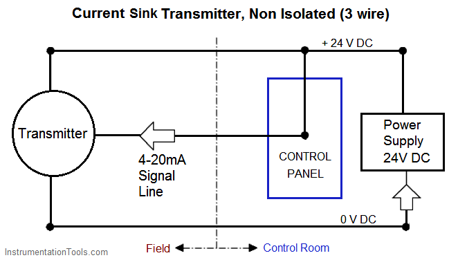
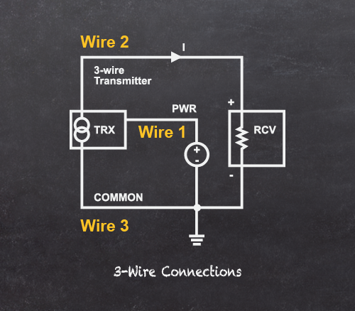
4..20mA Current Loops: 2, 3 and 4 Wire Transmitters The following figures show basic transmitter connection: Figure 2. 4 Wire transmitter. 3-Wire devices. The standard also describes a Type 3 connection type, or 3-wire transmitter loop, where the Transmitter and Receiver share a ground connection with power, and the transmitter uses a third wire to connect to power outside of the current loop.
Nikolay Bozov | Industrial Automation and Control
Transmitter Diagram - U Wiring Transmitter diagram. The actual wiring between the transmitter and the power supply depends upon whether it is a 2-wire or a 4-wire type. Next is a resonance stage and the final stage built with a minimum 1W transistor which must have a heatsink. A pair of 4011 NAND gate stages U1c and U1d are configured like a radio-frequency RF oscillator ...

What are 2-wire and 4-wire Transmitter Output Loops? - RealPars
Connecting 2-wire 4-20ma Transmitter to 6ES7331-7KF02-0AB0 ... Transmitter 6: CH6 (+) Terminal with Terminal (14) on the Card (-) Terminal with Terminal (15) on the Card. for the schematic wiring diagram its in the attachments. so, I would like to know if I can use 2-wire 4-20ma in the 8 channels or only in the first 4 channels

What are 2-Wire and 4-Wire Transmitter Output Loops?
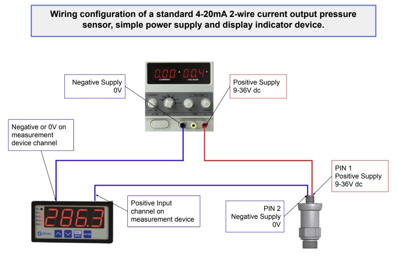
4 to 20 mA Current Loop Output Signal - SensorsONE 2 wire 4-20ma pressure transmitter wiring configuration. The diagram below below shows a simple wiring configuration for current loop pressure transmitter. It is assumed that the measurement device includes a sufficient load resistance for measuring a current loop. If the measurement device is a multi-meter it is unlikely to include sufficient ...
4-20 mA Transmitter Wiring Types : 2-Wire, 3-Wire, 4-Wire
2 Wire Pressure Transmitter Wiring Diagram - Wiring Sample A wiring diagram is a simplified standard photographic representation of an electrical circuit. 2 wire pressure transducer wiring diagram 4 20ma transmitter circuit diagram awesome 3 wire pressure transducer wiring diagram. A 2 wire transmitter has only 2 wires and is connected in series with the power supply and the plc. Wiring diagram pics ...

4-wire Transmitters Current Loops - InstrumentationTools
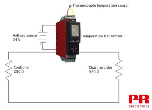
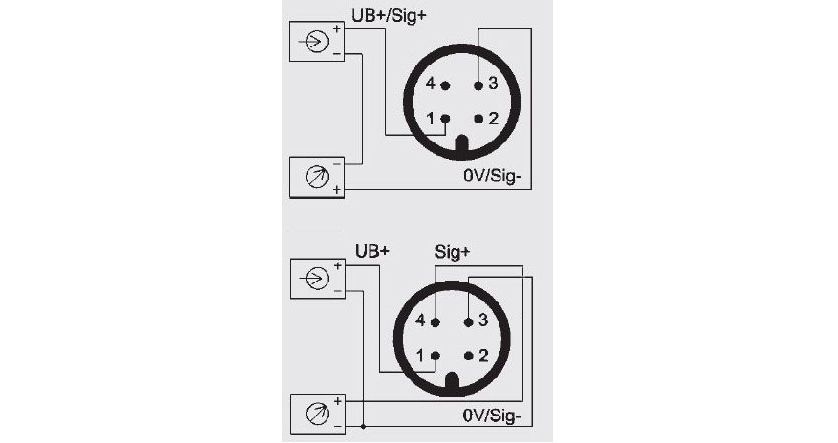
Diagram 2, 3, 4 - wire transmitter working principle and ... What is 4 wire transmitter? 4 wire transmitter wiring diagram. The figure above shows the wiring diagram of the four-wire transmitter. Most of the power supply is AC 220V, and some are DC 24V. DC4 ~ 20 ma output signals and the load resistance is 250 Ω, or DC0-10 ma, load resistance to 0-1.5 K Ω; Some also have mA and mV signals, but the load resistance or input resistance, depending on the output circuit form and different values. What is 3 wire transmitter? 3 wire transmitter wiring diagram

Current loop connection - DIVIZE industrial automation
2 Wire Pressure Transmitter Wiring Diagram - easywiring A wiring diagram is a streamlined standard pictorial depiction of an electric circuit. 2 wire pressure transducer wiring diagram 4 20ma transmitter circuit diagram awesome 3 wire pressure transducer wiring diagram. All devices in a 4 20 ma current loop need to be supplied power from somewhere in order to function.

CN0289 Flexible, 4 mA-to-20 mA, Loop-Powered Pressure Sensor ...
What are 2-Wire and 4-Wire Transmitter Output Loops ... C'mon over to where you can learn PLC programming faster and easier than you ever thought possible!===== Chec...
4...20 mA current loops - the fundamentals
4 wire transmitter on 2 wire Analog Input module - Entries ... Joined: 3/28/2010. Last visit: 2/11/2022. Posts: 774. Rating: (174) From the wiring connection diagram in the AI manual, I think Siemens means that a 2 wire input is for an active output from a field device which derives its power from the field device.
What is 4 wire transmitter and how to wire it? - Field ...
PDF 2-Wire & 4-Wire Transmitter Wiring Dia gra ms 2-Wire & 4-Wire Transmitter Wiring Dia gra ms Transmitter 4 - Wire Transmitter 4 - Wire 25 mA Common 25 mA 25 mA Common 25 mA 25 mA Common 25 mA 25 mA Common 7 7 6 5 4 3 2 Output 4-20mA 1 Output 4-20mA 120Vac power ... 4-Wire Transmitter P.O. Box 847 R-Safe Specialty Newman, CA 95360 Tel: 209-862-0230 Toll-free: 1-800-860-3088 Fax: 209-862-0380 ...
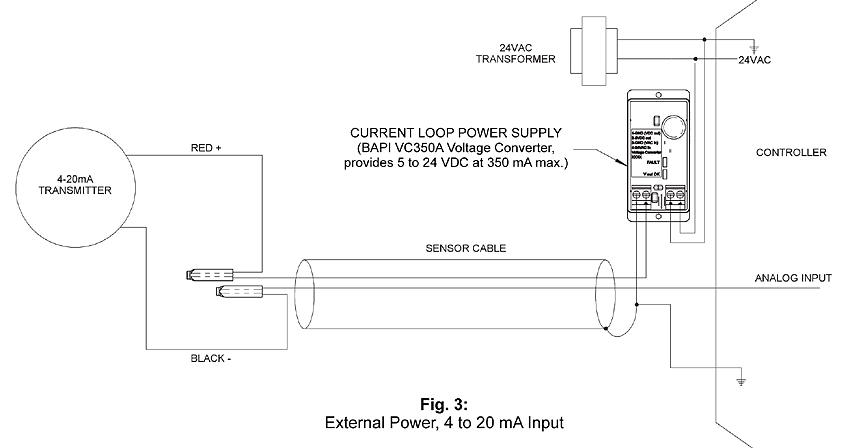
4 to 20 mA Current Loop Configurations - Application Note - BAPI
4 to 20 mA Current Loop Output Signal

Diagram 2, 3, 4 - wire transmitter working principle and ...
Introduction to the Two-Wire Transmitter and the 4-20mA ...

4-20 mA Transmitter Wiring Types: 2-Wire, 3-Wire, 4-Wire ...
4-20ma Pressure Transmitter Wiring
Back to Basics: Loop vs Line Power | Precision Digital
Difference of 4-20 mA in 2-wire & 3-wire technology - WIKA blog
Pt100 in 2-, 3- or 4-wire connection? - WIKA blog
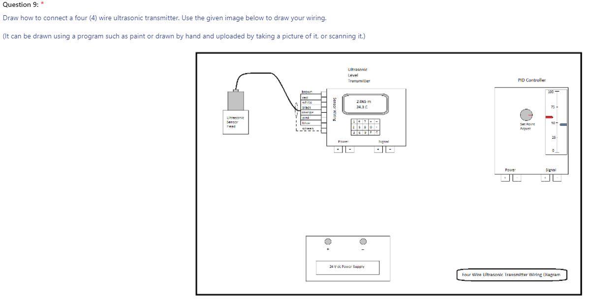
Solved Question 9:* Draw how to connect a four (4) wire ...

4 to 20 mA current loops made easy

4 - 20mA Transmitter Wiring Types: 2 -Wire, 3 - Wire & 4 ...

What is the difference between two wire and four wire ...

What are 2-wire and 4-wire Transmitter Output Loops? - RealPars
RTD Sensor Wiring | TC Inc
4-20ma Pressure Transmitter Wiring

Difference between 2, 3 and 4-wire RTD Configuration
AllenBradley 2085-IF8 2 wire wiring - PLCS.net - Interactive ...
Industrial Communications: 4-20 mA Current Loop - Allied ...

How to Implement a 4-20mA Transmitter with the MAX12900

4-20 mA Transmitter Wiring: 4wire Transmitter connection & 2wire Loop powered Transmitter connection

Electrical Connections & Wiring Guide - Dylix Corporation

4 - 20mA Transmitter Wiring Types: 2 -Wire, 3 - Wire & 4 ...

4-20 mA Current Loop Devices - Circuit Cellar

Planet Analog - 4-Wire Current-Loop Sensor Transmitters
0 Response to "39 4 Wire Transmitter Wiring Diagram"
Post a Comment