39 timer relay wiring diagram
› article › relay-wiring-diagramRelay Wiring Diagram: A Complete Tutorial | EdrawMax The diagram above is the 5 pin relay wiring diagram. There are different kinds of relays for different purposes. It can be used for various switching. Relay can be the best option to control electrical devices automatically. 5 pin is compromised of 3 main pins and an SPDT (single pole double throw). How to Use a Timer Relay (Syr-line) from Crouzet - YouTube DISCOVER THE MOST POWERFUL TIMERShttp://control.crouzet.com/syrlinetimersSyrelec brand becomes Syr-line, the new specialized range at Crouzet. Meet the first...
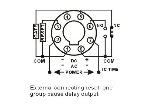
PDF Multi-functional Timer relay. Timer's wiring diagram ..... 5 2.1 Connecting 5amp timer ... During the circuit design with the timer relay and variety of timer configuration, questions such as

Timer relay wiring diagram
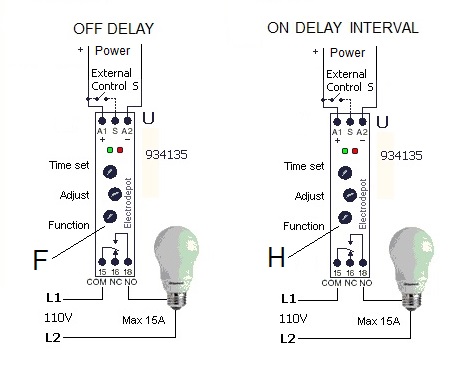
27-relay-timer-switch.pdf - AutomationDirect Relays and Timers ... QL Series Wiring Diagrams and Derating Curves. Wiring Diagrams ... Part Number. Price. Description. Dimensions and Wiring Diagrams.79 pages 8 pin timer relay wiring diagram - YouTube A timer relay is a combination of an electromechanical output relay and a control circuit the contacts will open or close before or after a preselected timed... PDF Multi-functional Timer relay. voltage, the time relay (t) Upon application of input begins. At the end of the time delay (t), the output is energized. Input voltage must be removed to reset the time delay relay & de-energize the output. The timer function #1 is ON DELAY, it allows to supply power after a period of time (t). There are two
Timer relay wiring diagram. Adjustable Timer Circuit Diagram with Relay Output 6 V/ 100 Ω SPST Relay Working When the power supply is given ,555 timer produces square wave at pin 3 as it is in astable mode. It gives a pulse width according to value of pot. It can be calculated as T( high) =0.693*(R1+R2)*C 1 T(low) =0.693*R1*C1 8 Pin Relay Wiring Diagram - Studying Diagrams This relay will be identified as having a middle 87b spade or no middle spade at all. Wiring Diagram Of 8 Pin Relay Electronic Paper. The electric timer allows a light point to be turned on from one or more places in the room and to leave this light point on for an adjustable period of time. 15 8 Pin Relay Diagram. Timer relay: Working principle, Applications, Basics Timer relay types. Timer relays provide a wide range of selectable functions so that users can customize their specific machine operations. There are lots of timing functions for timer relays. Some of them are: On delay timer relay. When the supply voltage is applied and the delay time is over, output contact changes the position. Finder Relay Wiring Diagram - Wiring Tech Wiring diagrams 1301 1312 and 1371 Type 1301 Step wiring diagram Red LED indication. Continuous relay ON Type 1312 Call reset relay Type 1301 Monostable wiring diagram Red LED indication. Pin On Relays And Contactors 1 2 pole relay range 40 31 1 pole 10 a 3 5 mm pin pitch 40 51 1 pole […]
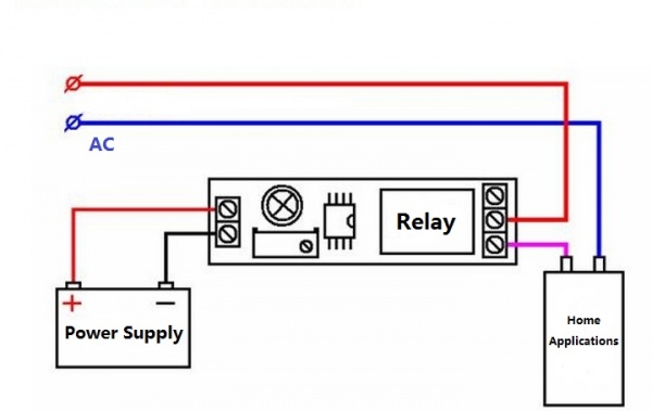
ELECTRONIC TIME RELAYS 2 “NO” SCHEME FOR TIMER ON IN DELTA. B/R Phase. : Use only with above given wiring diagram. ! 896-6835 & 896-6838. 1.Always follow instructions stated in ...1 page › off-delay-timer-relay-wiring-diagramoff delay timer relay wiring diagram - IOT Wiring Diagram Dec 11, 2021 · Off Delay Timer Relay Wiring Diagram. By IOT | December 11, 2021. 0 Comment. Solid state timer relay electrical academia using time delay relays to cycle a traffic signal 555 ic motor control systems part c electromechanical worksheet digital circuits how wire an off dol starter overrun the for 5 minutes quora circuit before turn on working ... Contactor And Relay Wiring Diagram - The Wiring Single Pole Contactor Relay Wiring Diagram 240v Single pole means that it can only control a single circuit and single throw means that there are only two positions the switch can be in one on and one off state mechanical relays do not The esd5 series is an accurate solid state delayed interval timer it offers a 1a steady 10a inrush output and ... PDF DROK Timer Relay P3: Relay will turn ON for time OP after getting a trigger signal and then turn relay OFF.Module will reset and stop timing if it gets a trigger signal again during delay time OP. P4: Relay will turn OFF for time CL after getting a trigger sighal and then relay will turn ON for time OP.Relay will turn OFF after finish timing.
8 Pin Timer Relay Wiring Diagram - Diagram Sketch Contactor Wiring Diagram With Timer Diagram Relay Wire . How To Connection 8 Pin Timer Relay With Diagrams Timer Relay Connection . Te Connectivity 12v Dc Coil Non Latching Relay 3pdt 10a Switching Current Plug In Mt321012 6 1393091 8 Rs Components Electrical Projects Relay Electrical Circuit Diagram . 8 Pin Timer Relay Wiring Diagram | Basic Timer Connection ... 8 Pin Timer Relay Wiring Diagram | Basic Timer Connection And Function |Three Phase Main Distribution Board Wiring | 3 Phase Distribution MDB Box Wiring Diag... 12 Volt Time delay relay - How it works and how to wire ... The BU508TD Time delay relay is a unique relay that can only be found at ... Relay And Contactor Wiring Diagram - The Wiring Relay and contactor wiring diagram.Single Pole Contactor Relay Wiring Diagram 240v Single pole means that it can only control a single circuit and single throw means that there are only two positions the switch can be in one on and one off state mechanical relays do not The esd5 series is an accurate solid state delayed interval timer it offers a 1a steady 10a inrush output and is available ...
Add fan to boiler: http://waterheatertimer.org/add-fan-to ...
8 Pin Relay Wiring Diagram - Wiring Diagram How To Wire Pin Timers - 8 Pin Relay Wiring Diagram. Wiring Diagram comes with several easy to stick to Wiring Diagram Directions. It is intended to aid all the common consumer in creating a proper system. These instructions will likely be easy to grasp and use. With this particular guide, you may be able to see how each and every component ...

Amazon.com: DC12V Delay Timer Time Relay H3Y-2 0-60S Second ...
Time Delay Relay Basics: Relay Circuit and Applications Therefore, most of the control circuits are in the next level circuit by the time relay output. After the timing completion signal is accurately ...Oct 20, 2020 · Uploaded by RSP SupplyWhat is time-delay relay?How does a time delay relay work?

Time Delay Relay Basics: Relay Circuit and Applications
› timer-relay-connection-diagramtimer relay connection diagram - Wiring Diagram and Schematics Thermostat Delay Relay Timer Circuit Homemade Projects. Solid state timer relay time delay circuit with 555 8 pin wiring diagram using ic digital 12v 24v 326 327 series relays on dc 110 super led home automation grt8 s1 asymmetric cycler best motor control systems part c js14p mini timing ics module applications and specifications to cycle a traffic signal driving thermostat single function ...

Time Delay Relay using 555 Timer IC
› 2021/08/8-pin-timer-relay8 pin timer relay wiring diagram - electrical and electronics ... Aug 23, 2021 · Cours August 23, 2021 ,electrical engineering. 8 pin timer relay wiring diagram. The electric timer allows a light point to be turned on from one or more places in the room, and to leave this light point on for an adjustable period of time. The control points are pushbuttons with indicator lights (in order to be able to locate them in the event of extinction).

Single Relay Timer (Arduino 1 Channel Relay) ⋆ Teach Coding ...
PDF Multi-functional Timer relay. voltage, the time relay (t) Upon application of input begins. At the end of the time delay (t), the output is energized. Input voltage must be removed to reset the time delay relay & de-energize the output. The timer function #1 is ON DELAY, it allows to supply power after a period of time (t). There are two
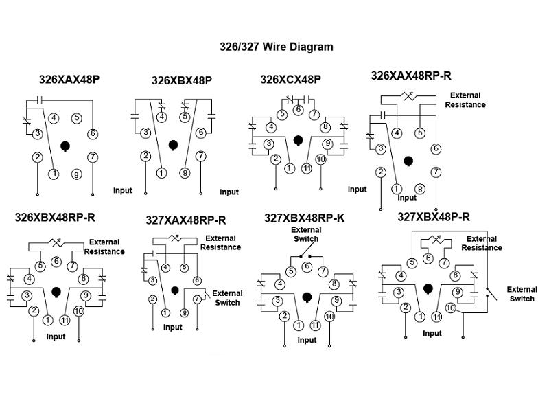
326/327 Series - Time Delay Relays On Struthers-Dunn
8 pin timer relay wiring diagram - YouTube A timer relay is a combination of an electromechanical output relay and a control circuit the contacts will open or close before or after a preselected timed...
Solid State Timer | Solid State Relay Timer | Electrical Academia
27-relay-timer-switch.pdf - AutomationDirect Relays and Timers ... QL Series Wiring Diagrams and Derating Curves. Wiring Diagrams ... Part Number. Price. Description. Dimensions and Wiring Diagrams.79 pages

Double Delay Time Relay, Best Factory Supplier in China - Geya

Time Delay Relay Basics: Relay Circuit and Applications

Industrial Motor Control: Timing Relays
Digital Timer Relay, 8 Pin, 24V DC/110-240V AC | ATO.com

12V Relay With Timer Switch : 4 Steps - Instructables
5.3: Time-delay Relays - Workforce LibreTexts

8 Pin Timer Wiring Diagram
Digital Timer Relay, 8 Pin, 12V/24V/220V | ATO.com
timer - How to wire this delay relay switch - Electrical ...

On Delay Timer Connection Diagram and Testing - ETechnoG

Learning Engineering: 8 Pin Timer Relay Wiring Diagram ...
ICS Time Delay Module Applications and Wiring

Industrial Motor Control: Timing Relays
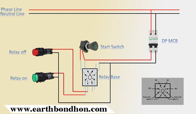
Timer Testing Wiring Diagram – Earth Bondhon

Single Function Time Relay GRT8-A1 - GEYA

Need to wire in a Dayton 11 pin time delay relay to pull in a ...
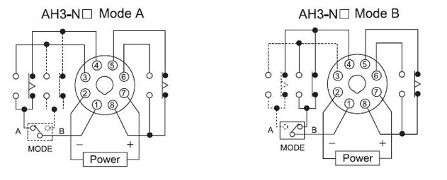
AH3-N 3A On-delay time super time delay relay 220v_Inductive ...

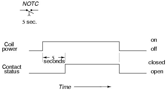
Time-Delay Electromechanical Relays Worksheet - Digital Circuits
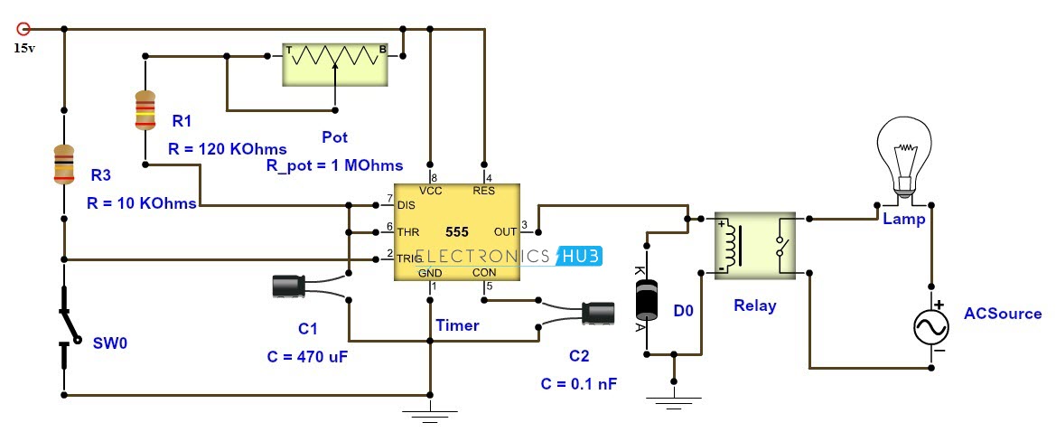
Adjustable Timer Circuit Diagram with Relay Output

20 Most Recent Amperite Dayton Solid State Timer On Questions ...
ST3PF time delay relay electronic general purpose relay ...

Timer Relay - 10 minutes
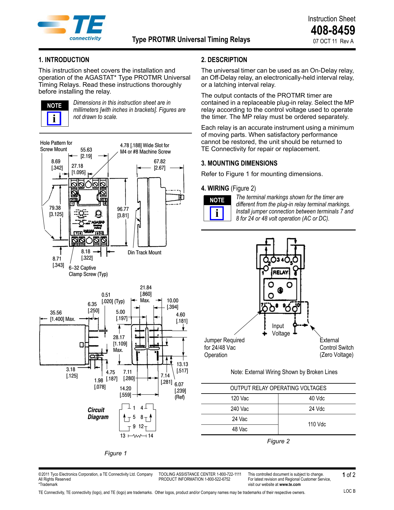
Instruction Sheet Type PROTMR Universal Timing Relays | Manualzz

How to wire Pin timers

Rear A/C condenser fan relay wiring diagram - Pelican Parts ...
Special Applications with SPDT Relays
DIN timer latching relay toggle
Timer Adjustable 12V Delay Realy Module - ITEAD Wiki
DIN timer latching relay toggle
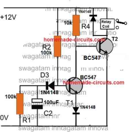
Simple Delay Timer Circuits Explained - Homemade Circuit Projects

Track Relay Wiring
UCTRONICS DC 12V Time Delay Relay Module for Smart Home, Tachograph, GPS, PLC Control, Industrial Control, Electronic Experiment, Arduino Robot
0 Response to "39 timer relay wiring diagram"
Post a Comment