40 safety relay wiring diagram
Understanding Relays & Wiring Diagrams | Swe-Check A relay is an electrically operated switch. Learn how to wire a 4 or 5 pin relay with our wiring diagrams and understand how relays work. PDF Guardmaster Configurable Safety Relay Wiring Diagram Guardmaster Configurable Safety Relay Catalog Number 440C-CR30-22BBB Wiring Diagram Important User Information Read this document and the documents listed in the additional resources section about installation, configuration, and operation of this equipment before you install, configure, operate, or maintain this product.
Circuit Diagrams of Safety Components | Technical Guide This part presents basic examples in which a G9SA (Safety Relay Unit), G9SX (Flexible Safety Unit), F3SX (Safety Controller) and F3SP-B1P (Safety Light ...

Safety relay wiring diagram
Automotive Relay Diagram Sign In | Order Status | Request a Quote | Blog | Our Catalog · Relays are switches controlled by electrical power, like another switch, computer or control module. The purpose of a relay is to automate this power to switch electrical circuits on and off at particular times. PDF ESR5-NO-31-24VAC-DC Safety relay - Eaton Depending on the external wiring, up to category 4, PL e according to EN ISO 13849-1 or SILCL 3 according to EN 62061 can be achieved. The safety relay is equipped with three enabling current paths and one sig-naling current path that drop out without delay according to stop category 0. Features • Emergency stop and safety door monitoring Best Relay Wiring Diagram 5 Pin Wiring ... | Electrical diagram, ... Sep 18, 2018 - Best Relay Wiring Diagram 5 Pin Wiring ...
Safety relay wiring diagram. Pilz Safety Relay Wiring Diagram - schematron.org Pilz Safety Relay Wiring Diagram 16.01.2019 7 Comments Two channels with monitored start and relay control with feedback the reset circuit (start button) with closed input circuits (safety switch button pressed). Emergency Stop Relays, Safety Gate Monitors. Pilz Pnoz X3 Safety Relay Wiring Diagram Principle circuit diagram.E-STOP relays, safety gate monitors Pilz GmbH & Co. KG, Felix-Wankel-Straße 2, Ostfildern, Germany E-STOP wiring (dual-channel) Safety gate (dual-channel) Montage_PNOZ_X The safety relay should be installed in a control cabinet with a protec-. Safety Circuit Examples of Safety Components | Technical Guide ... This part provides control circuit (safety circuit) examples grouped by category. These circuits are made up of electric interlocking mechanisms that incorporate protective door and safety switches. Wiring Diagram For Safety Relay - Wiring Diagram Line Sentry Safety Relays Original Instructions Safety Manual Bt50 T Relay Expansion Safety Relay Wiring Diagram Information Siemens Electrical Wires Cable Png Pngegg Msr38 D Dp Safety Relay Circuit Design Eng Tips Three Safety Relays In One Is That Possible United Kingdom Im0061236 Png Safety Relay Emergency Stop With Galvanic Isolation
Wiring the Safety Relay - Avigilon Wiring the Safety Relay. The contacts on the pluggable terminal blocks are are rated for 24V, 2A maximum, and 16 to 26 gauge wires. You can wire the Safety Relay to an electric door strike directly or to a door controller panel managed by the ACM software.. There are two ways to directly wire the Safety Relay to an electric door strike, depending on how the door is configured to act when power ... How To Wire A Relay How To Wire A Relay, Let me show you how to wire a relay. Instructions on how relays work. Safety relays | UE48-2OS | SICK Overview. The UE48-20S safety relay can connect all common safety solutions. In the field of emergency stop pushbuttons, mechanical and non-contact safety switches it not only controls the signals, but controls the cross circuit detection and sequence monitoring as well. The signals of the opto-electronic protective device are directly taken ... Next Generation Guardmaster Safety Relay (GSR) - Literature ... The SI safety relay generates test pulses through the E-stop circuits to detect cross channel shorts and shorts to power and ground. The drive detects some faults in the safe-circuit of the drive and the drive executes a Safe Torque Off stop. The safety system does not detect a short circuit from S1 to S2. Ratings
Safety Relays | How and Where Safety Relays Work An overview of Where to find Safety Relays and how they work, including a Safety Relay Product Overview video and Safety Relay Diagrams. PDF Monitoring Safety Relays - RS Components Safety Relays 4-37 Monitoring Safety Relays Minotaur MSR126R/T Product Selection Dimensions—mm (inches) Block Diagram Typical Wiring Diagrams Safety Outputs Auxiliary Outputs Reset Input Power Supply Catalogue Number 2 N.O. None Automatic/Manual Light Curtain or Single Channel (MSR126T) 24V AC/DC 440R-N23117 115V AC 440R-N23116 230V AC 440R ... Car Relay Diagram | Electrical diagram, Electrical circuit diagram, ... Oct 12, 2019 - This Pin was discovered by Noussa Benois. Discover (and save!) your own Pins on Pinterest Formidable Wiring A Safety Switch Cam Superline Trailer ... Neutral Safety Switch Wiring Diagram 5 Pin Relay Electrical Kill Treadmill Motor Speed Control Circuit And Plug Outlet. 4l60e Transmission Neutral Safety Switch Wiring Diagram Flow Chart Lighting Trailer Light Four Prong Plug Limit Circuit.
Guide to Safety Relays and Safety Circuits
Circuit Diagrams of Safety Components | Technical Guide This part presents basic examples in which a G9SA (Safety Relay Unit), G9SX (Flexible Safety Unit), F3SX (Safety Controller) and F3SP-B1P (Safety Light ...
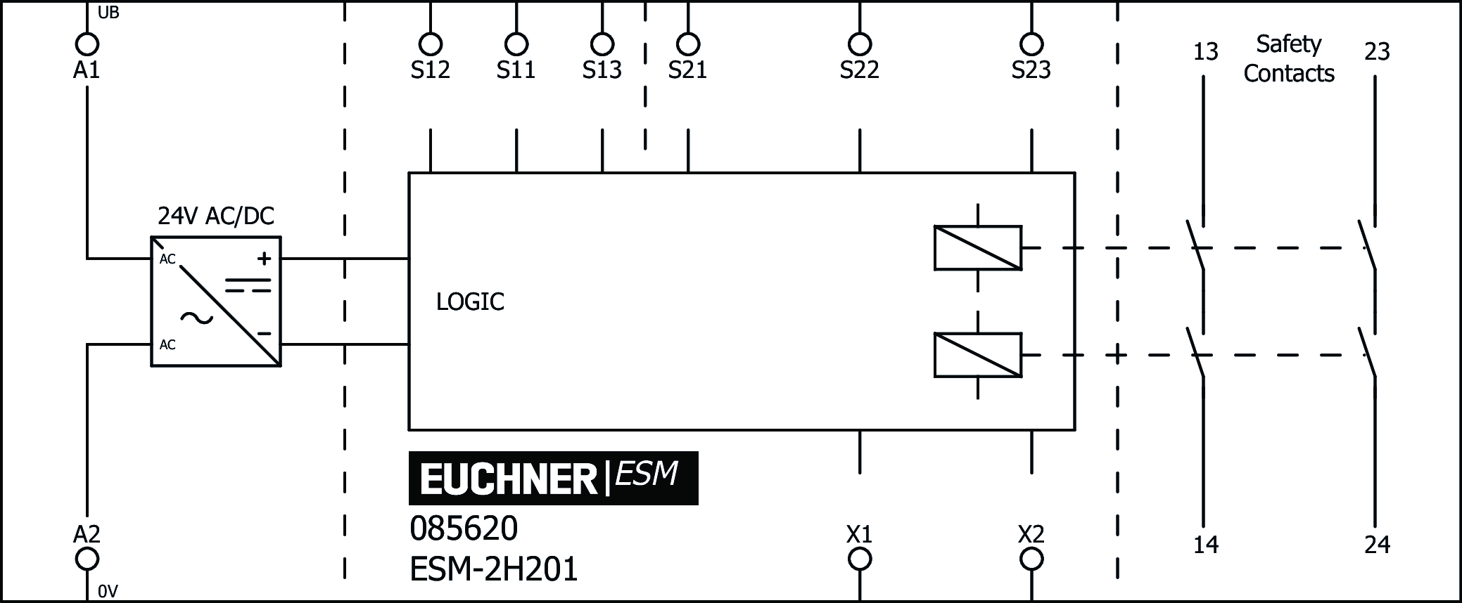
ESM-2H201 | EUCHNER – More than safety.
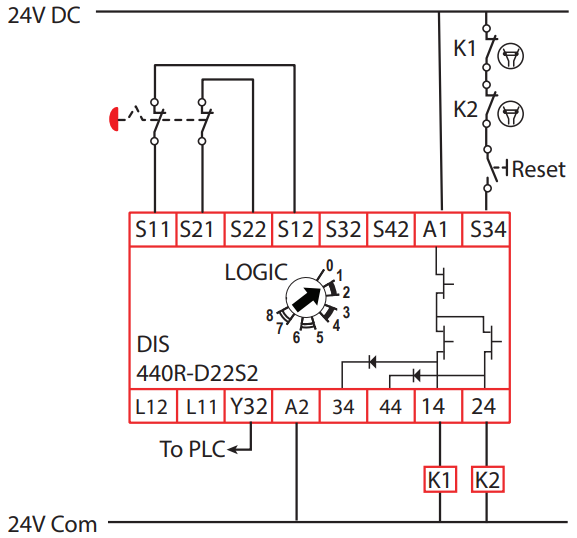
PDF Guardmaster Safety Relays User Manual Guardmaster Safety Relays Catalog Numbers 440R-S13R2, 440R-S12R2, 440R-D22R2, 440R-D22S2, 440R-EM4R2, 440R-EM4R2D User Manual Original Instructions
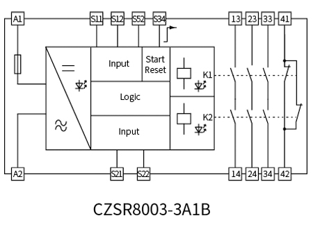
CHENZHU | E-Stop Button, Safety Gate Safety Relay
Circuit Diagrams of Safety Components | Technical Guide This part presents basic examples in which a G9SA (Safety Relay Unit), G9SX (Flexible Safety Unit), F3SX (Safety Controller) and F3SP-B1P (Safety Light Curtain Controller) or D9M-CD1 (Safety Mat Controller) are used to configure an electrical interlock device connecting inputs and outputs.

Wiring safety relay Pilz PNOZ and emergency stop button.
Allen Bradley Safety Relay Wiring Diagram - Wirings Diagram There are two things which are going to be present in any Allen Bradley Safety Relay Wiring Diagram. The first element is symbol that indicate electrical element in the circuit. A circuit is generally composed by various components. Another thing that you will come across a circuit diagram would be lines.

Next Generation Guardmaster Safety Relay (GSR) - PDF Free ...
PDF Connection examples for wiring the safety relay G1501S
Safety manual BT50(T) Safety relay / Expansion relay
Application guide Safety relays of machinery and technical ... Norstat Safety, Automation and Connectivity Solutions for the Industrial Marketplace. Safety Light Curtains, Muting Light Curtains & Safety Controllers, Safety Interlocks and Non Contact Safety Switches, Safety Relays and Audible and Visual Signaling Devices.

MSR38-D/DP safety relay circuit - Circuit design - Eng-Tips
Safety relay/safety relays - Pilz US The safety relays PNOZ monitor safety functions such as emergency stop, safety gates, light barriers, light curtains, two-hand controls, speed, standstill and much more besides.Every day, PNOZ safety relays prove themselves in millions of applications worldwide. In 1987 Pilz patented the first emergency stop relay to protect man and machine.

Example 1: system wiring | Rockwell Automation 440R-S845AER ...
PDF Safety Relays - Logic Control to facilitate the choice of safety relay or combinations of safety relays, please see: - the table below dividing the safety relays into application fields - the table on the opposite page showing possible input and output options - the relevant data sheet giving comprehensive information about each specific safety relay - the circuit diagram for …

First time doing a safety relay circuit, can someone verify ...
PDF Siemens Safety Relays Wiring Manual - Electro-Matic Products Safety relays with automatic start can be used up to Category 3: The feedback circuit is statically monitored. monitored start For a monitored start, an enable signal is generated when the ON button is pressed. This function is also designated as static operation and is specified for EMERGENCY STOP devices (EN 60204-1, conscious action).
.png)
DIN Rail Safety Relays - Phoenix Contact | Mouser
Wiring Diagram For Pilz Safety Relay - Wiring Diagram Line How To Use Pilz S Safety Relay There Is A Wiring Diagram Inside E Stop Relays Up To Category 2 En 954 1 Pnoz X1 Manualzz Relays Pilz Safety Relay Pnoz X3 Business 774030 Relais De Sécurité Pilz Pza 24v C 1 Canal Contact Rs Components Pilz Pnoz X6 Wiring Diagram Pdf Manualslib
Performance Level is reduced by series connection with ...
5 Pin Wiring Diagram | Electrical circuit diagram, Electrical ... Apr 22, 2019 - This Pin was discovered by Irving gutierrez barquero. Discover (and save!) your own Pins on Pinterest
VIPER Safety Relays Type: SCR-i (with added diagnostics)
Safety relay - Wikipedia Safety relays must always be designed in such a way that, if wired correctly, neither a fault in the device nor an external fault caused by the sensor or actuator will lead to the loss of the safety function. A normal relay uses a wire coil and the mechanical movement of the metal contacts ...

60 Lovely Allen Bradley Guardmaster Safety Relay Wiring ...
Pilz Pnoz X3 Safety Relay Wiring Diagram - schematron.org Pilz Pnoz X3 Safety Relay Wiring Diagram 30.09.2018 3 Comments Discuss PILZ PNOZ X3 - Trying to Unerstand in the Industrial Electrician have the internal wiring diagram, i am sure you can google such a diagram. Safety relays are usually adaptable to provide coverage for differering.

Safety relay internal structure. | Download Scientific Diagram
Connection examples for wiring the safety relay G1501S - IFM ifm electronic gmbh – Automation made in Germany. Quality, innovation, exceptional service and more than 40 years close to the user: ifm electronic is the right choice in terms of automation.
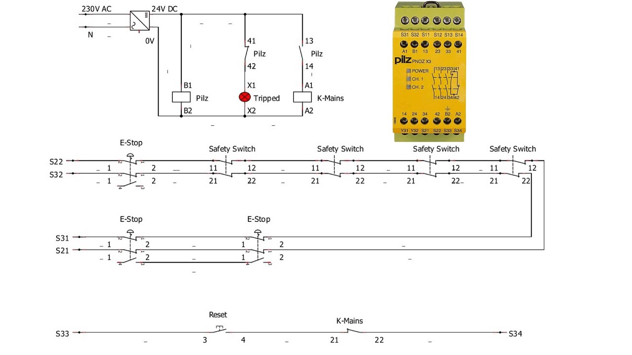
How to wire up Pilz Safety Relay Pnoz X3, Safety switches, Estops, Light curtains -Part 1 of 3 #Pilz
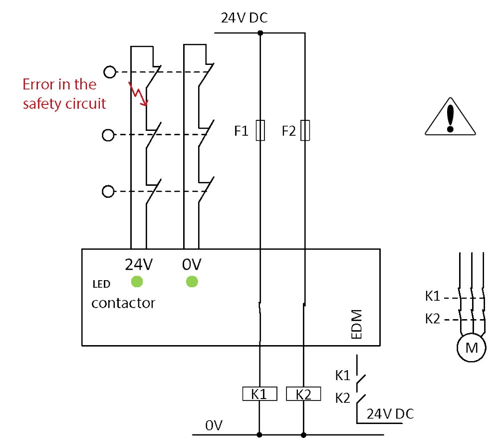
Looking Good Safety Relay Wiring Diagram Ceiling Fan Motor ... Safety relay wiring diagram. January 14 2019 april 12 2020. 0 vdc 24 vdc automatic. By measuring flow of current the safety relay checks for welded contact sets and wire breaks. In case of a faulty wiring of the inputs the unit goes to the fail safe state safety deactivation. March 9 2019 april 12 2020 wiring diagram by anna r. There are two ...
/How%20to%20use%20Pilz's%20safety%20relay%20(There%20is%20a%20wiring%20diagram%20inside)5.jpg)
How to use Pilz's safety relay (There is a wiring diagram inside)
700-2.14: Safety Relays - Rockwell Automation Access Product and Software Documentation, explore Product and Service Content organized by Industry, learn about Services, Training and Technical Support, read about our Capabilities and Engineering Expertise

How to wire Safety Relay ? Emergency Stop Dual Channel Monitoring with reset || Easy Explained
Guide to Safety Relays and Safety Circuits - PLC Academy A safety relay is a great and simple illustration of a safety circuit and how it works. It is very important to understand that safety relays are here for a reason. And that reason is to eliminate or reduce risks. When machine safety is applied, you will often have to build a safety circuit.

Circuit Diagrams of Safety Components | Technical Guide ...
Allen Bradley GuardMaster Safety Relay Wiring Tutorial June 25, 2020 - In this tutorial, we will take a look at the GuardMaster Dual Input safety relay paired with a SensaGuard safety sensor, understand the application it may be used in, the wiring scheme of both devices, and how they interact between each other.

Help me understand Safety Relay Schematic : r ...
Safety Relay and Light Checker wiring question | Yamaha ... If you study the wiring diagram, you'll see tail light power comes from the ignition switch to the light checker on a blue/yellow wire. Tail light power runs out of the light checker on a blue wire to the tail light. You will need to jumper the blue/yellow to the blue in the harness plug once the light checker is removed. member28833 Race the wind
/How%20to%20use%20Pilz's%20safety%20relay%20(There%20is%20a%20wiring%20diagram%20inside).jpg)
How to use Pilz's safety relay (There is a wiring diagram inside)
How to wire a 4 pin relay | Step-by-Step Guide November 27, 2021 - Relays are the electrically operated switches that are widely being used in electronics circuits these days to control multiple operations. They work on
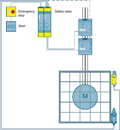
SIRIUS Safety Integrated: Emergency stop and protective door ...
Allen Bradley Safety Relay Wiring Diagram - Wiring Diagram Bul. 440R Guardmaster Safety Relays (Di, Dis, Si, Ci, Glp, Em, And - Allen Bradley Safety Relay Wiring Diagram Wiring Diagram comes with several easy to stick to Wiring Diagram Instructions. It's intended to assist all the typical user in developing a suitable method. These guidelines will be easy to comprehend and implement.
Wieland Shop
Relay Wiring Diagrams | the12volt.com May 4, 2020 - We use cookies to personalize content, in our forums to recognize members and guests and their preferences, to complete web forms, to display third party ads, and to analyze our traffic. Personalized ads have been disabled for end users in the European Economic Area (EEA).

440R-S13R2 - Guardmaster Compatibility Input Safety Relay (CI ...
PDF PNOZ X Safety Relays Application Manual • PMD: Electronic monitoring relays such as voltage or true power monitors, for example. • PNOZ: Safety relays for simple plant and machinery with up to 4 safety functions. Safe monitoring of e-stops, safety gates and light curtains/light grids, for example. • PNOZmulti: The safety circuit is created using a simple confi guration tool.

What is Safety Relay? - Utmel
PDF Safety Relays - Namrata Trade Links Safety Classification Cat. 4 per EN 954-1 (ISO 13849-1), SIL CL3 per EN IEC 62061, PLe per ISO 13849-1 ... Block Diagram Typical Wiring Diagrams Light Curtain, Monitored Manual Reset, Monitored Output Single Channel E-Stop, Automatic Reset, No Output Monitoring

Safety Relay PLC Output Resetting : r/PLC
PDF PREVENTA™ XPS Safety Relays Emergency stop and limit ... PREVENTA™ XPS Safety Relays Emergency stop and limit switch monitoring ... Wiring Diagrams XPSAV module with an Emergency stop push button with 1 N.C. contact, automatic start or unmonitored start (1) Jumper for automatic start. (2) Instantaneous opening safety outputs (stop category 0).
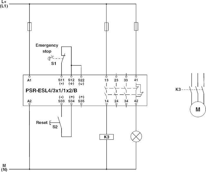
Phoenix Contact 2981059 PSR-SCP- 24UC/ESL4/3X1/1X2/B safety relay, 24VAC/DC, screw
Relay Wiring Diagram: A Complete Tutorial | EdrawMax The diagram above is the 5 pin relay wiring diagram. There are different kinds of relays for different purposes. It can be used for various switching. Relay can be the best option to control electrical devices automatically. 5 pin is compromised of 3 main pins and an SPDT (single pole double throw).

Emergency Stop with External Safety Relay
PDF Wiring guide to ifm safety light curtains and safety relays Wiring diagram when not using a safety relay Reference. OY8xxS blanking versions. Title OY wiring Rev2 Author: usliyu Created Date: 5/6/2013 3:44:18 PM

Wiring safety relay SRB301 and emergency stop. - YouTube ...
PDF Safety Relay - AutomationDirect Safety Relays Selection Chart Part Number Price Marking Type Voltage Outputs LG5929-60-100-61 $107.00 Safety relay extension module 24 VAC/VDC 5 N.O./1 N.C. Safety Relay Extenson Module Specification Table General Specifications Temperature Storage: -25°C to 85°C (-13°F to 185°F) Operating: -15°C to 55°C (5°F to 131°F) Altitude < 2,000 ...

Schneider Electric Preventa 230V ac Safety Relay - Dual ...
Best Relay Wiring Diagram 5 Pin Wiring ... | Electrical diagram, ... Sep 18, 2018 - Best Relay Wiring Diagram 5 Pin Wiring ...

Take control of safety | United Kingdom
PDF ESR5-NO-31-24VAC-DC Safety relay - Eaton Depending on the external wiring, up to category 4, PL e according to EN ISO 13849-1 or SILCL 3 according to EN 62061 can be achieved. The safety relay is equipped with three enabling current paths and one sig-naling current path that drop out without delay according to stop category 0. Features • Emergency stop and safety door monitoring

Circuit Diagrams of Safety Components | Technical Guide ...
Automotive Relay Diagram Sign In | Order Status | Request a Quote | Blog | Our Catalog · Relays are switches controlled by electrical power, like another switch, computer or control module. The purpose of a relay is to automate this power to switch electrical circuits on and off at particular times.

Phoenix Contact Safety relay, PSR-MC34 | MISUMI
/How%20to%20use%20Pilz's%20safety%20relay%20(There%20is%20a%20wiring%20diagram%20inside)2.jpg)
How to use Pilz's safety relay (There is a wiring diagram inside)

Safety Circuit Examples of Safety Components | Technical ...
Allen Bradley GuardMaster Safety Relay Wiring Tutorial
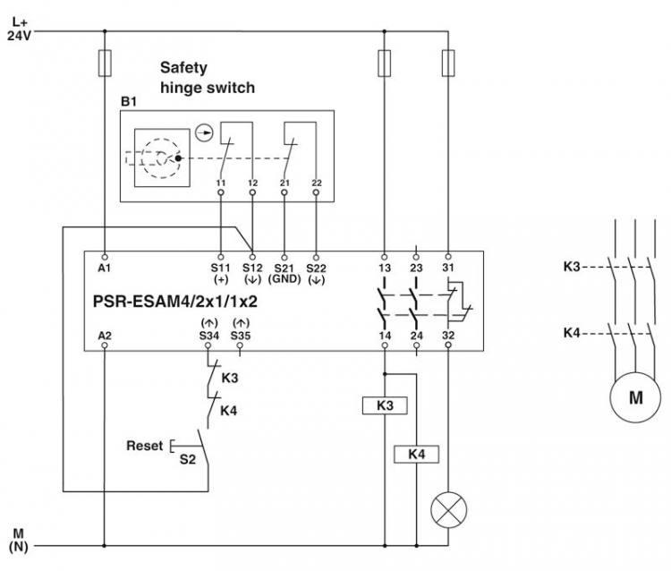
Phoenix Contact 2900525 PSR-SCP- 24UC/ESAM4/2X1/1X2 safety relay, 24VAC/DC, screw
Application Note SensaGuard Switches & an E-Stop Switch Wired ...
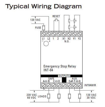
How To Install Sentrol Integrity Series INT-04 Emergency-Stop ...
Three safety relays in one...is that possible? | United Kingdom

Safe Machine Design: A Mechanical Engineer's Guide to, uh ...
0 Response to "40 safety relay wiring diagram"
Post a Comment