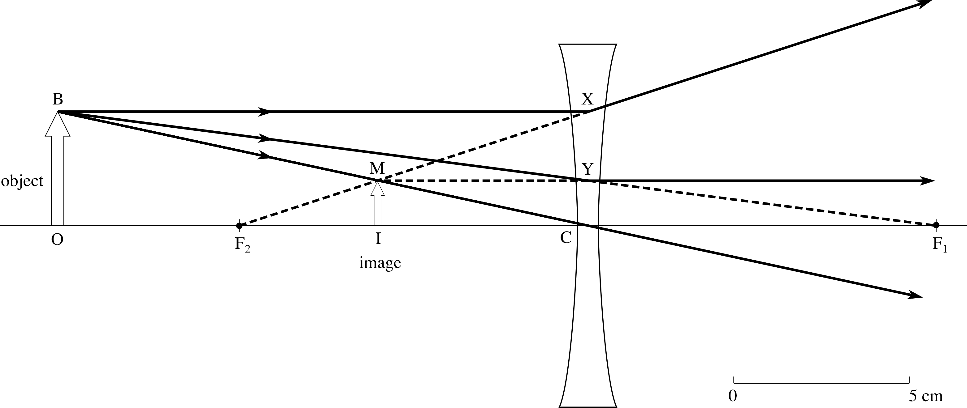
41 draw a ray diagram of the lens system in part d
Modern Parallel and Distributed Python: A Quick Tutorial on Ray Ray occupies a unique middle ground. Instead of introducing new concepts. Ray takes the existing concepts of functions and classes and translates them to A more concise implementation of the two aggregation schemes. The only difference between the two blocks of code is whether the output of... ICSE Solutions for Class 10 Biology - The Nervous System ... 04.12.2019 · Question 3: Draw a labeled diagram of a myelinated neuron. Answer: Question 4: Draw a diagram of the human eye as seen in a vertical section and label the parts which suits the following descriptions relating to the: (i) photosensitive layer of the eye. (ii) structure which is responsible for holding the eye lens in its position.
Important Questions for CBSE Class 12 Physics ... - VEDANTU Free PDF download of Important Questions with Answers for CBSE Class 12 Physics Chapter 9 - Ray Optics and Optical Instruments prepared by expert Physics teachers from latest edition of CBSE(NCERT) books. Register online for Physics tuition on Vedantu.com to score more marks in CBSE board examination.

Draw a ray diagram of the lens system in part d
PDF PowerPoint Presentation | Thin Lenses; Ray Tracing Lenses and Optical Instruments. Key Points • Thin Lenses; Ray Tracing • Combinations of Lenses • The Human Eye; Corrective Lenses • Compound Microscope. The power of a lens (p=1/f) is positive if it is converging and negative if it is diverging. Problem Solving: Thin Lenses. 1. Draw a ray diagram. Refraction Ray Diagrams (6.2.4) | AQA GCSE... | Save My Exams Refraction Ray Diagrams. Refraction occurs when light passes a boundary between two different transparent media. At the boundary, the rays of light undergo a change in This line is perpendicular to the surface of the boundaries and is usually represented by a straight dashed or dotted line. Free Online Diagram Editor Free editor to create online diagrams. Use our diagram editor to make Flowcharts, UML diagrams, ER diagrams, Network Diagrams, Mockups, floorplans and many more.
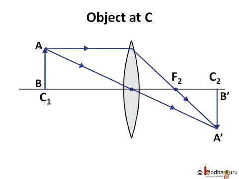
Draw a ray diagram of the lens system in part d. PDF Chapter-9.pmd | 9.5.3 Power of a lens In the case of spherical lenses, the principal axis is the line joining the optical centre with its where R is the radius of curvature of the mirror. The geometry of reflection of an incident ray is shown in Fig. FIGURE 9.5 Ray diagram for image formation by a concave mirror. curvature of a concave mirror or... Draw a labelled Ray diagram of an image of a distant object formed... Draw the energy level diagram of a hydrogen atom; and draw arrows to show transitions responsible for The positive sign has been taken for the reason that the distance of image I' from C2 is measured in the direction of incident ray. If C2 I = v, then the focal length of lens is given by Flour Mill Rye [4MH368] Since 1926 the Moulins d’Antoine has stood out for the quality of their products and notably for their flour “seigle de Margeride”. Ardent Mills offers a variety of refined and whole rye flours to satisfy any color or flavor preference. Dark rye flour tends to be the least refined, coarser ground and holds the most health benefits in flour form. #1 dark, plump rye berries. 5 cups dark ... Geometrical Construction of Ray Diagrams | Nikon's MicroscopyU Explore how characteristic light rays and the principal ray can be utilized along with strategic lens parameters to determine ray traces through an optical system. The positions of the object and image, with respect to the lens and focal points, are controlled by the Object Position slider, which...
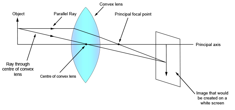
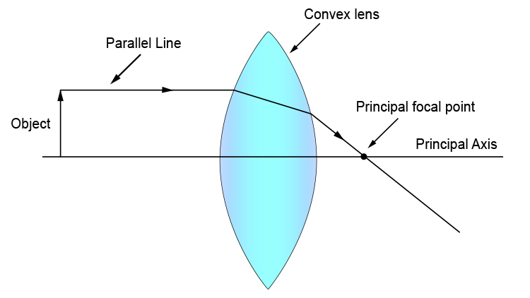
Thin Lenses and Lens Systems When light from an object passes through a lens, an image of the object is generally formed. Light is scattered from the object in all directions, but to draw a ray diagram, only two of the following three principal rays are needed to locate the image. Part 3: Lens System and Corrective Lenses. optics - Inconsistency in ray diagram - Physics Stack Exchange As soon as you draw some of the "missing" rays, you discover that the diagram becomes inconsistent. Check out the link below which incorporates the ray you are questioning. Place the object roughly midway between C and F as in your diagram then play with the object height slider. Ray Diagrams for Lenses Ray Diagrams for Lenses. The image formed by a single lens can be located and sized with three principal rays. The "three principal rays" which are used for visualizing the image location and size are: A ray from the top of the object proceeding parallel to the centerline perpendicular to the lens. Ray Optics Simulation - Home | Glass (Ideal lens) Ray Optics Simulation. An open-source web app to simulate the reflection and refraction of light. Suitable for education and demonstration. Glass with any shapes constructed from line segments and circular arcs, including prisms and "spherical" lenses. Glass (Ideal lens).
Ray Diagrams - Lenses - YouTube 122 - Ray Diagrams - LensesIn this video Paul Andersen explains how ray diagrams for lenses can be used to determine the size and location of a refracted... Curved mirror - Wikipedia A ray drawn from the top of the object to the mirror surface vertex (where the optical axis The point at which these two rays meet is the image point corresponding to the top of the object. up to order 1. The derivations of the ray matrices of a convex spherical mirror and a thin lens are very similar. oPhysics Lens Refraction and Spherical Aberration. Lenses & Chromatic Aberration. 2D Image Formation by Lenses. Optics of the Human Eye. Description Simulation of image formation in concave and convex lenses. Move the tip of the "Object" arrow to move the object. What is CRT (Cathode Ray Tube)? definition, block diagram and... Cathode ray tube, CRT is the heart of CRO which produces images when electron beam from the back of the tube strikes the fluorescent screen with sufficient energy. To obtain high emission of electrons at a moderate temperature a layer of barium and strontium oxide is deposited at the end of the cathode.
a Schematic representation of a real image formed by using a ...
Working Principle and Parts of a Compound Microscope... It has a series of lenses to converge on the object, light rays coming from the light source. After passing through the object, the light rays enter into the objective. Depending upon the required magnification, one of the two eyepieces is inserted into the draw tube before viewing.
Physics Tutorial: Refraction and the Ray Model of Light
Can anyone suggest a free software for drawing optical schematics ? This diagram was drawn as part of a guide to new users of the tweezer system as although specific ray optics are not accurately shown, ALL optical elements are shown with their relative positions and orientations. Attached are ray diagrams for both the trapping optics and illumination optics. again...

16.3 Lenses | Texas Gateway
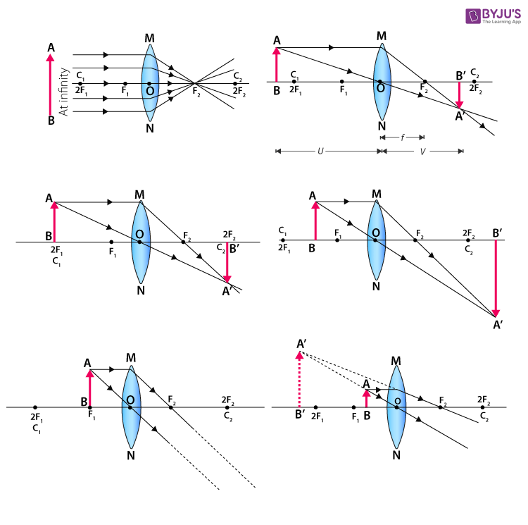
PÀ£ÁðlPÀ ¥ËæqsÀ²PÀët ¥ÀjÃPÁë ªÀÄAqÀ½ 1. There are three parts in the question paper. PART A : Physics, PART B : Chemistry, ... Draw the ray diagram of image formed when the object is kept beyond 2F 1 of the convex lens. With the help of the diagram, mention the position and nature of the image formed. (F 1 : principal focus of the lens) OR Draw the ray diagram when of image formed the object is kept beyond …
Ray Diagrams for Lenses
Ray Marching | Michael Walczyk As I hinted at already, when we use ray marching, we aren't dealing with polygons anymore. So, a lot of the things that we're used to in a typical 3D toolkit - geometry, lights, cameras - are nonexistent. But if we don't have points, lines, triangles, and meshes, how do we render anything?
Physics Tutorial: Refraction and the Ray Model of Light
Optical Lens Design Using a Spreadsheet / Excel: The ... Let’s draw a simple lens system. First of all, I’d like for us to try to draw a few lenses so we can express them visually. I’m going to use graph paper, a ruler, compass, and draw it out. Yes, even in the digital age we live in, I’d like to try this. Spreadsheets break down the lens into components, and drawing the lens is the same, conceptually. Radius R, distance on axis t, ray ...
Physics – लेंस Part 3 – Ray Diagram of Image Formation in Convex Lens – Hindi
The Ultimate Class Diagram Tutorial to Help Model Your Systems Easily UML class diagram tutorial to learn about class diagram notations, class diagram definition, how to draw a class diagram and best practices. The first one shows the class's name, while the middle one shows the class's attributes which are the characteristics of the objects.
Cyberphysics - Rules for drawing ray diagrams
Ray Marching and Signed Distance Functions This is where the ray marching algorithm comes in! Just as in raytracing, we select a position for the camera, put a grid in front of it, send rays from the camera through each point in the grid, with each grid point corresponding to a pixel in the output image.
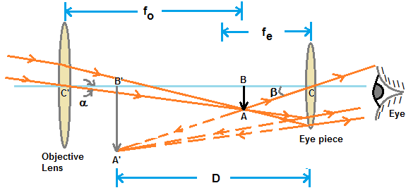
draw a ray diagram of astronomical telescope and derive the ...
Symbols for All Diagrams | Edraw - Edrawsoft Industrial Control System Diagram Symbols. Pre-drawn industrial control system diagram symbols represent wire, elbow bus, terminal list, inware flow, etc. These symbols help create accurate diagrams and documentation.

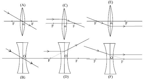
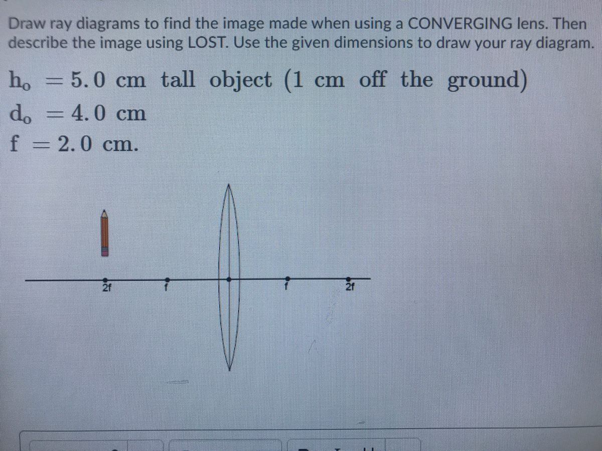
Converging & Diverging Lenses Ray Diagrams DIRECTIONS: Use at ...
Chapter 33 Lenses and Optical Instruments - ppt video online download 4 33-1 Thin Lenses; Ray Tracing Thin lenses are those whose thickness is small compared to their 15 33-2 The Thin Lens Equation; Magnification Problem Solving: Thin Lenses Draw a ray diagram. Using the lens equation and the position of the focused rays, and solving for the focal length of the...

Draw ray diagrams to represent the nature, position and ...
Convex Lens - Ray diagram, Image Formation, Table - Teachoo For a Convex Lens, object can be kept at different positions. Hence, we take different cases. Case 1 - Object is Placed at infinity. In this Case, Object is kept far away from lens (almost at infinite distance). So, we draw rays parallel to principal axis.
Method for drawing ray diagrams - convex lens
What are the three principal rays that are drawn to construct the ray... (ii) A ray of light incident parallel to the principal axis of the lens, after refraction passes through the second focus F2 (in a convex lens) or appears to > In Figure 36.26a, assume the gray object arrow is replaced by one that is much taller than the lens. (a) How many rays from the top of the object will...

Draw a ray diagram to show the use of a convex lens for the ...
Molecular Expressions Microscopy Primer: Anatomy of the Microscope... In the dual-lens system (Figure 4), a spherical wavefront emanating from light source point S(1), and located at a distance d from the optical axis of the Construction of Ray Diagrams. Learn how the application of geometrical optics can be utilized to determine the size and location of images formed...
To Find Image Distance For Varying Distance Of A Concave Lens
Thin Film Interference | Physics - Lumen Learning Ray 2 in Figure 2 travels a greater distance than ray 1. For light incident perpendicular to the surface, ray 2 travels a distance approximately 2 ... Draw a diagram of the situation. Labeling the diagram is useful. Step 5. Make a list of what is given or can be inferred from the problem as stated (identify the knowns). Step 6. Solve the appropriate equation for the quantity to be …
Method for drawing ray diagrams - convex lens
Geometric Optics: Geometrical Optics | SparkNotes Ray Tracing. Often it will be useful to determine the approximate position of an image, given the position of the object and the focal length in a lens or mirror system without resorting to the lens equation. We can do this by drawing diagrams and mapping out the path of the light rays.

How to Draw Ray Diagrams - Shalom Education
How to draw a ray diagram of a convex lens of magnification... - Quora Now we can start drawing the ray diagram. Draw the lens and the optical axis. Mark the focus at a distance of. There are actually two different formulas from which you can calculate magnification of a simple optical system (a single thin lens, or thin lens equivalent).

Drawing ray diagrams for a converging lens - The Fizzics ...
00. This is equivalent to a single prism with one of its ... 11.03.2022 · When analyzing a compound lens, it is convenient to treat the two lenses sequentially with the image of the first lens acting as the object o f the second lens and so on. 4: Ray Tracing: Nearby Object As mentioned, a diverging lens will usually form a vir-tual image. Record the measurement, in centimeters, in So, i need some idea to set up the fresnel lens …
Rules of Drawing Ray Diagram in Lens - QS Study
Physics Tutorial: Refraction and the Ray Model of Light To draw these ray diagrams, we will have to recall the three rules of refraction for a double convex lens: Any incident ray traveling parallel to the principal axis of a converging lens will A ray diagram for the case in which the object is located in front of the focal point is shown in the diagram at the right.

To Find Image Distance For Varying Distance Of A Concave Lens
Image Formation by Lenses | Physics | Solutions (Ray Tracing) The lens in which light rays that enter it parallel to its axis cross one another at a single point on the opposite side To find the power of the lens, we must first convert the focal length to meters; then, we substitute this Using the rules of ray tracing and making a scale drawing with paper and pencil, like...
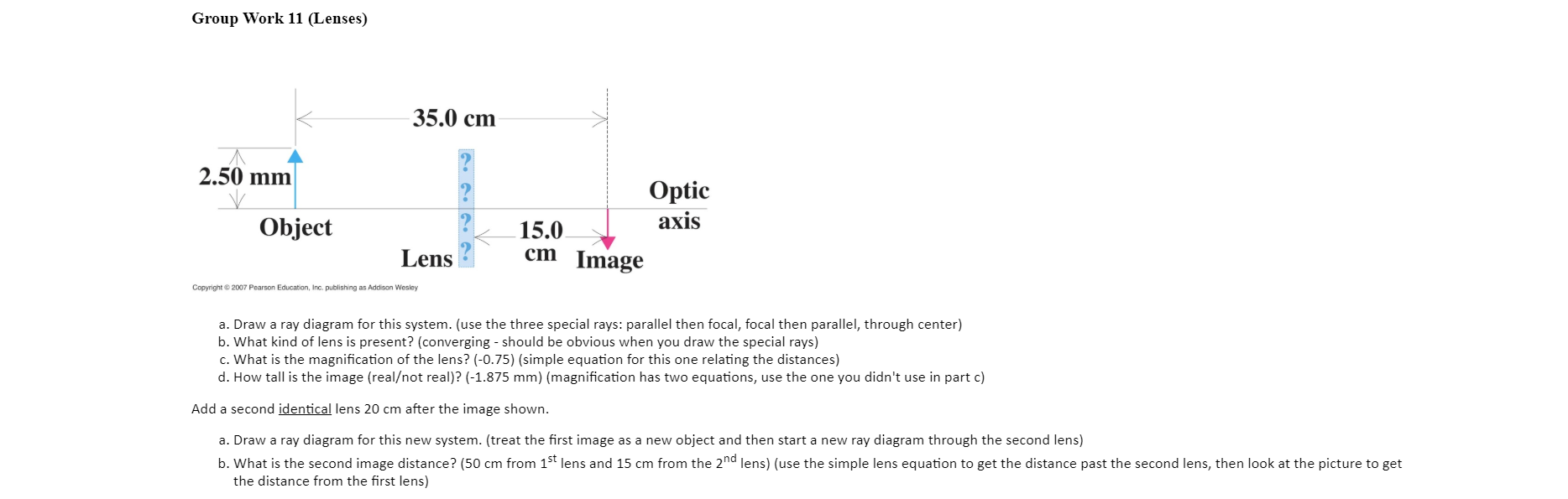
Solved Group Work 11 (Lenses) 35.0 cm 2.50 mm V Optic axis ...
NCERT Solutions for Class 8 Science Chapter 16 Light ... 04.10.2019 · Draw a ray diagram to show incident ray, reflected ray, normal, angle of incidence,, angle of reflection; if the angle of incidence is 45° Answer: NCERT Solutions for Class 8 Science Chapter 16 – 5 Mark Questions and Answers. Question 1. How can you compare human eye with a photographic camera ? [MSE (Chandigarh) 2008] Answer: Human Eye: Photographic …

How to Draw Ray Diagrams - Shalom Education
EdrawMax Online | All-in-One Diagram Tool EdrawMax Online is the all-in-one diagram tool for all your diagramming needs. It allows to create over 280 types of diagrams, including flowchart, floor plan, genogram, network diagram and more. Its intuitive interface and powerful symbol libraries make your create easier, which is the best Visio...

A) Draw the ray diagram to find the approximate location of ...
Convex and concave lenses - Lenses and ray diagrams - OCR... Learn about and revise lenses, images and ray diagrams with GCSE Bitesize Physics. Parallel light rays that enter the lens converge. They come together at a point called the principal focus. In a ray diagram, a convex lens is drawn as a vertical line with outward facing arrows to indicate the shape of...
Ray Diagrams for Lenses
Free Online Diagram Editor Free editor to create online diagrams. Use our diagram editor to make Flowcharts, UML diagrams, ER diagrams, Network Diagrams, Mockups, floorplans and many more.

Systematic design of microscope objectives. Part I: System ...
Refraction Ray Diagrams (6.2.4) | AQA GCSE... | Save My Exams Refraction Ray Diagrams. Refraction occurs when light passes a boundary between two different transparent media. At the boundary, the rays of light undergo a change in This line is perpendicular to the surface of the boundaries and is usually represented by a straight dashed or dotted line.
PPLATO | FLAP | PHYS 6.3: Optical elements: prisms, lenses ...
PDF PowerPoint Presentation | Thin Lenses; Ray Tracing Lenses and Optical Instruments. Key Points • Thin Lenses; Ray Tracing • Combinations of Lenses • The Human Eye; Corrective Lenses • Compound Microscope. The power of a lens (p=1/f) is positive if it is converging and negative if it is diverging. Problem Solving: Thin Lenses. 1. Draw a ray diagram.

Comparison between TEM and OM. The two ray diagrams ...
Ray Diagram PRELAB LAB

Draw a well - labeled diagram for image formation by a convex ...
Physics Tutorial: Refraction and the Ray Model of Light
Answered: Draw ray diagrams to find the image… | bartleby

Course: S4: Physics , Topic: Unit 1: Thin lenses
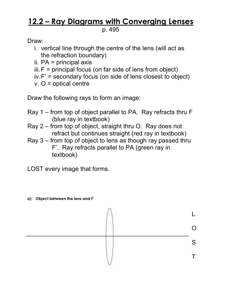
12.2 lenses drawing ray diagrams

Drawing ray diagrams for a converging lens - The Fizzics ...
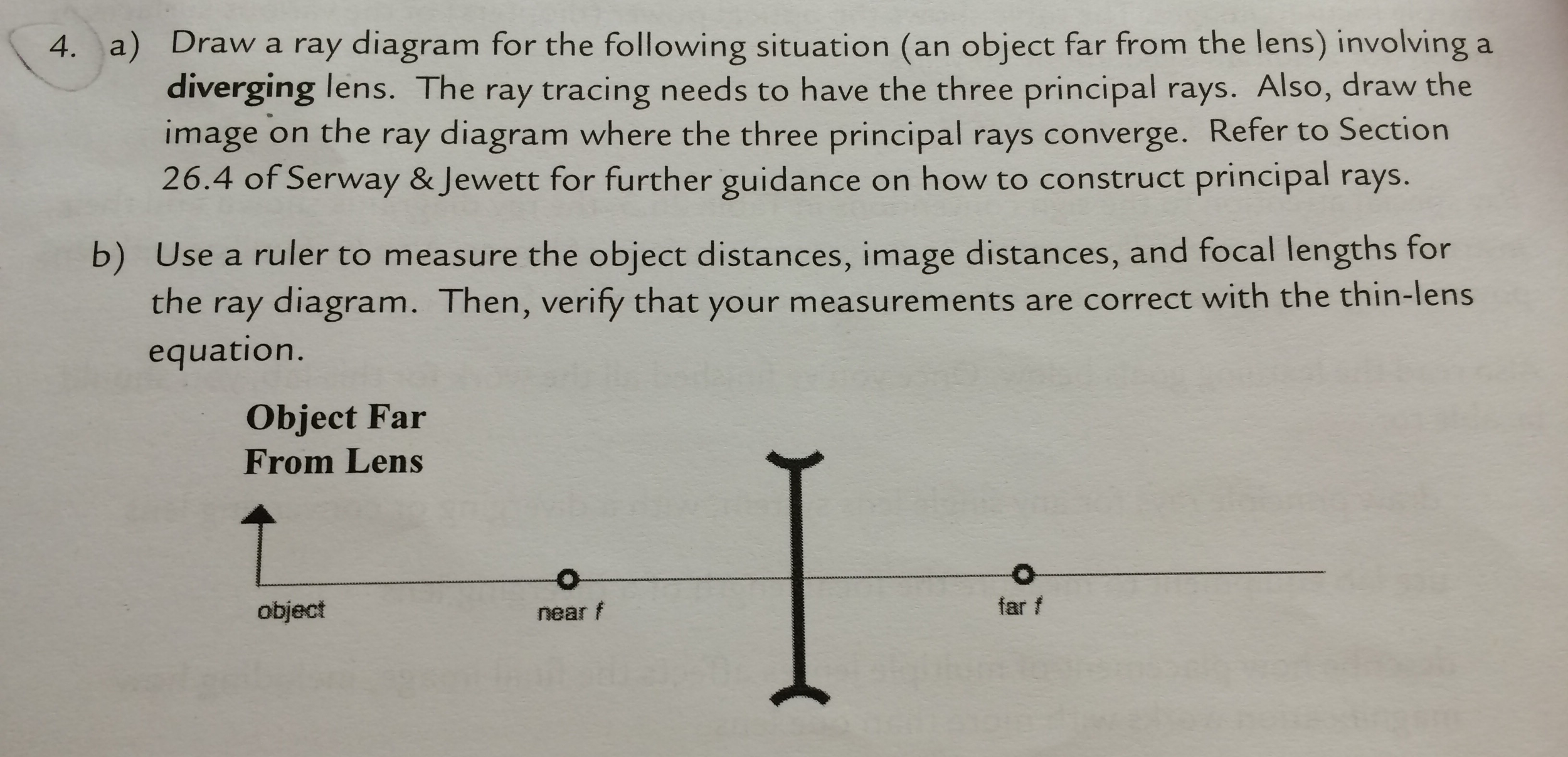
Solved A) Draw a ray diagram for the following situation (an ...
Physics Tutorial: Refraction and the Ray Model of Light

Convex/Concave - lenses & mirrors: CBSE board practice
![Solved] draw the ray diagram showing the image formation by a ...](https://hi-static.z-dn.net/files/d53/e7c5088db42873d426d28336b31c1bda.jpg)
Solved] draw the ray diagram showing the image formation by a ...

Systematic design of microscope objectives. Part I: System ...
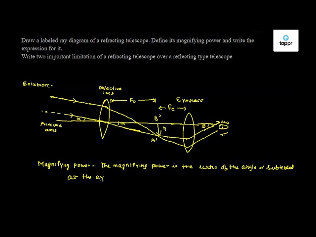
Draw a labeled ray diagram of a refracting telescope. Define its magnifying power and write the expression for it. Write two important limitation of a refracting telescope over a reflecting type ...

Ray Diagrams — Isaac Physics
Draw a ray diagram to show the formation of the image of an ...
Objective Lenses for Trapped Ion Experiments with Beryllium
0 Response to "41 draw a ray diagram of the lens system in part d"
Post a Comment