41 fe si phase diagram
An assessment of the Fe-C-Si system - NASA/ADS An evaluation of the parameters describing the thermodynamic properties of the phases involved in the binary Fe-Si system has been achieved, mainly based on values of the silicon activity in the body-centered cubic (bcc) phase and on knowledge of the phase diagram. The A2-B2 ordering reaction of the bcc phase has been included. The FeSi phase diagram to 150 GPa - Lord - 2010 - Journal ... Second, the high-pressure phase diagram of FeSi will help to constrain the topology of the Fe-rich portion of the Fe-Si system, which is important in determining the distribution of Si within the core and lower mantle at the present day and during core formation [Dobson et al., 2002; Santamaría-Pérez and Boehler, 2008].
The Fe-FeSi phase diagram at Mercury’s core conditions ... Jan 19, 2022 · Literature on the Fe–Si system at high pressures report a series of miscibility gaps in the solid phase, between Si-poor hcp or fcc phases and an Si-rich B2 phase 26,28,38, or between the Si ...
Fe si phase diagram
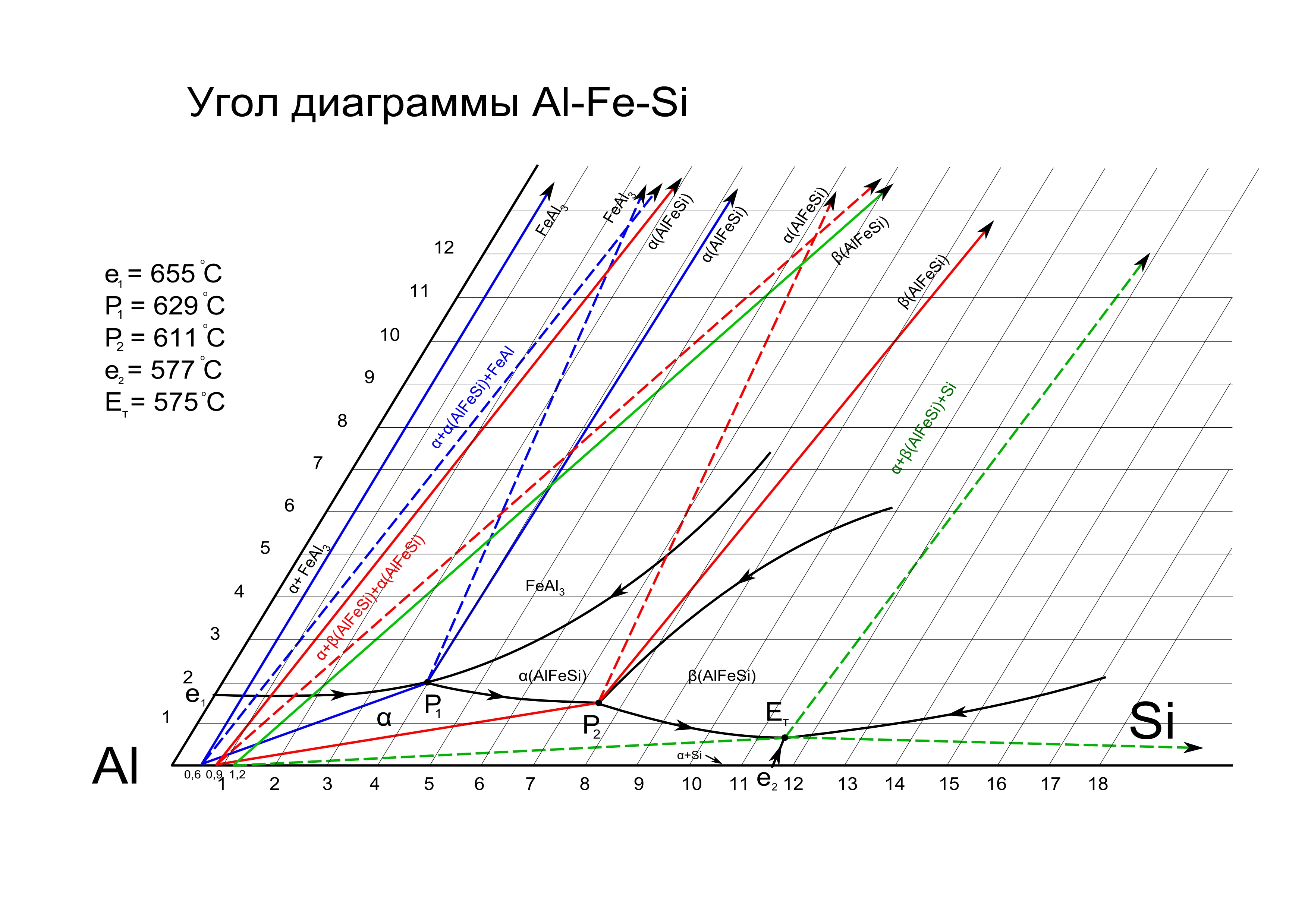
PDF The iron-iron carbide (Fe-Fe3C) phase diagram Si Mn W Mo Review Fe-C phase diagram • 2 important points-Eutectoid (B): γ⇒α+Fe 3C-Eutectic (A): L ⇒γ+Fe 3C Fe 3 C (cementite) 1600 1400 1200 1000 800 600 400 0 12 3 4 5 66.7 L γ (austenite) γ+L γ+Fe 3C α+Fe 3C α + γ L+Fe 3C δ (Fe) C o, wt% C 1148°C T(°C) α 727°C = Teutectoid A R S 4.30 Result: Pearlite = alternating layers ... PDF Chapter 1 Alloys of the Al-Fe-Mn-Si System A general view of the Al-Fe-Si phase diagram, the projections of the liquidus and solidus surfaces in the aluminum corner in the diagram are given in Figure 1.1. These data suggest that a decrease in the Hquidus and solidus temperatures (in Al-rich alloys) is primarily due to the concentration of sihcon, the effect of iron being much smaller. Phase Diagrams - an overview | ScienceDirect Topics Phase diagram: Phase diagram measurement was carried out by mixing concentrated JR400 solution and an anionic surfactant solution using deionized water in a 25 ml vial. All samples were put at 25 °C for at least one day. Then the appearance of each sample was checked visually. Viscosity measurement: The samples for phase diagram were used.
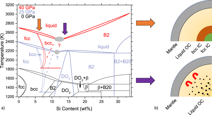
Fe si phase diagram. (PDF) Fe-Ni-Si (Iron-Nickel-Silicon) | Vijayaraghavan ... Ternary Phase Equilibria Binary Systems With starting metals of 99.99% Fe, 99.99% Ni, and In the Fe-Ni phase diagram, a continuous face-centered 99.95% Si, [2009Zha] arc-melted under Ar atm 24 ternary cubic solid solution (denoted c) forms between cFe and Ni alloys. Phase Diagrams of Fe-Si Alloys under High Pressures Phase Diagrams of Fe-Si Alloys under High Pressures J. F. Lin,1 D.L. Heinz,1,2 A. J. Campbell,1 J. M. Devine1 1Department of the Geophysical Sciences and 2James Franck Institute, The University of Chicago, Chicago, IL, U.S.A. Introduction Iron is the most abundant element in the Earth’s core. However, the density of the outer core is about 10 ... Making low-alloyed steel strong and tough by designing a ... In the present steel, Mn and C is enriched in the lath-like M(A) phase and Si is enriched in bainite lath. This alloying element segregation induces austenite memory to form a fine lath structure with alternative ferrite and reverted austenite during the intercritical process (see details in Figs. S6, S7 and “Supplementary Note”). Phase equilibria and structural investigations in the ... The ternary phase reactions in the system Al-Fe-Si were studied by DTA analysis of samples situated in six different vertical sections at 5 at.%. Al and at constant Fe contents of 27, 35, 40, 50 and 60 at.%. Two heating- and cooling-cycles were performed in each measurement.
Metamorphic Reactions - Tulane University Notice that the isograd represents the point on the phase diagram, above where the geothermal gradient intersects the boundary for the reaction: Al 2 Si 4 O 10 (OH) 2 <=> Al 2 SiO 5 + 3SiO 2 + H 2 O Pyrophyllite Kyanite Qtz fluid Metallography of Steels - University of Cambridge Phase Diagram We shall interpret microstructrures in the context of the iron-carbon equilibrium phase diagram, even though steels inevitably contain other solutes, whether by design or as impurities. The diagram is nevertheless useful since the transformation behaviour of austenite does not change dramatically unless the steel has a large concentration of solutes. Fe-Si Phase Diagram [16] and alloy quench temperatures ... Download scientific diagram | Fe-Si Phase Diagram [16] and alloy quench temperatures. from publication: Purification of Metallurgical Silicon using Iron as an Impurity Getter Part I: Growth and ... Microstructural Characterization and Phase Diagram ... A systematic characterization of a less known Al, Fe, Mn, and Si phase in a SiC particulate-reinforced 2014Al composite (SiC p /2014Al) was performed. In addition to the expected CuAl 2 phase, the Al, Fe, Mn, and Si phase was formed as either an adhesion (>1 µ m) onto SiC in the as-cast composite, or as a precipitate (<100 nm) in the matrix after hot extrusion.
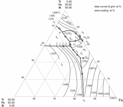
Phase Diagram - Google Search 計算熱力学はいわば"物性推算法"の一つであり、用いる熱力学データベースも、もっとも良さそうな"推算値"で構成されています。. これらは様々な情報に基づき、細心の注意を払って推定されたものですが、間違いや問題はあり得ます。. 従って、それ ... Computer calculations of metastable and stable Fe-C-Si phase ... Computer calculations of metastable and stable Fe-C-Si phase diagrams from binary thermodynamic properties Computer calculations of metastable and stable Fe-C-Si phase diagrams from binary thermodynamic properties. Download File. r_8627100.pdf (1004.34 KB) Date. 1986. Authors. Chueh, Shan-Chang. Journal Title. Journal ISSN. Triangular Plots in Metamorphic Petrology - Tulane University In the diagram below, a new phase, AC appears and mineral ABC disappears. ... (Mg,Al,Fe) 12 (Si,Al) 8 O 20 (OH) 16. Thus we have several possibilities for writing the formula for chlorite, and depending on which formula we use, chlorite will plot at different locations on the diagrams. Fe-Si-Ti Ternary Phase Diagram Evaluation - SpringerMaterials Fe-Si-Ti Ternary Phase Diagram Evaluation. Phase diagrams, crystallographic and thermodynamic data. Wei Xiong, Yong Du, Chao Zhang and MSIT® Abstract.
Teach Yourself Phase Diagrams and Phase Transformations
Alloy steel - Wikipedia Alloy steel is steel that is alloyed with a variety of elements in total amounts between 1.0% and 50% by weight to improve its mechanical properties.Alloy steels are broken down into two groups: low alloy steels and high alloy steels. The difference between the two is disputed. Smith and Hashemi define the difference at 4.0%, while Degarmo, et al., define it at 8.0%.
Phase Diagrams Evaluation
Fe-La-Si Ternary Phase Diagram Evaluation - SpringerMaterials Fe-La-Si Ternary Phase Diagram Evaluation Phase diagrams, crystallographic and thermodynamic data Gabriele Cacciamani and MSIT® Abstract This report for the ternary system Fe-La-Si discusses binary systems, solid phases, isothermal sections, thermodynamics, and materials properties and applications. For a more recent literature collection see:
Ferro-Silicon – IspatGuru
SpMCBN - Spencer Group M-C-N-B-Si Alloy Phase ... - CRCT SpMCBN - Spencer Group M-C-N-B-Si Alloy Phase Diagrams (837) Click on a system to display the phase diagram.
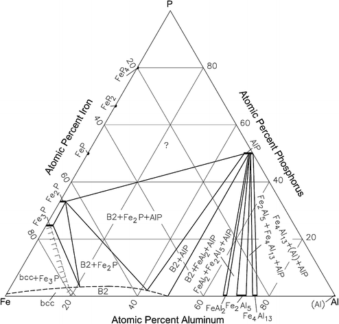
Phase Diagram Updates and Evaluations of the Al-Fe-P, B-Fe-U ...
[PDF] Assessment of the ternary Fe-Si-B phase diagram ... DOI: 10.1016/J.CALPHAD.2013.08.001 Corpus ID: 54550236; Assessment of the ternary Fe-Si-B phase diagram @article{Poletti2013AssessmentOT, title={Assessment of the ternary Fe-Si-B phase diagram}, author={Marco Gabriele Poletti and Livio Battezzati}, journal={Calphad-computer Coupling of Phase Diagrams and Thermochemistry}, year={2013}, volume={43}, pages={40-47} }
Perple_X vs THERMOCALC and/or Thermo-Calc
Portion of Fe-Al-Si Phase diagram calculated by Thermo ... Download scientific diagram | Portion of Fe-Al-Si Phase diagram calculated by Thermo-Calc™. from publication: Study on the Formation of Reaction Phase to Si Addition in Boron Steel Hot-Dipped in ...
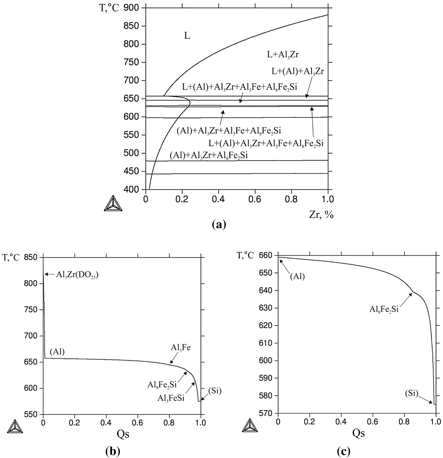
Figure 1 | Structure and Properties of Al-0.6%Zr-0.4%Fe-0.4 ...
Dynamic structural evolution of iron catalysts involving ... 4.2.2022 · The computed phase diagram for Fe species as a function of chemical potential of carbon (μ C) and oxygen (μ O) is shown in Fig. 8B. The calculated free energies of reactants (CO 2 /H 2 /N 2 = 21:63:16) is located at the red dot in the figure, which falls in the Fe 5 C 2 domain.
File:Al-Fe-Si 1.jpg - Wikimedia Commons
The FeSi phase diagram to 150 GPa - AGU Journals subsolidus phase diagram of FeSi are directly relevant to the CMB region. Second, the high‐pressure phase diagram of FeSi will help to constrain the topology of the Fe‐rich portion of the Fe‐Si system, which is important in deter- mining the distribution of Si within the core and lower mantle at the present day and during core formation

Assessment of the ternary Fe–Si–B phase diagram - ScienceDirect
PDF Phase relations in the Fe-FeSi system at high pressures ... 98 and outer core, assuming a predominantly Fe-Si core. These phase diagrams can be applied to 99 studies of other planetary cores, and will serve as a basis for future studies on multi-component 100 systems of candidate core materials. 101 102 103 2. Experimental methods 104 The Fe-9Si starting material (Goodfellow Corporation) was analyzed by ...
Phase Diagrams | Shuanglin Chen
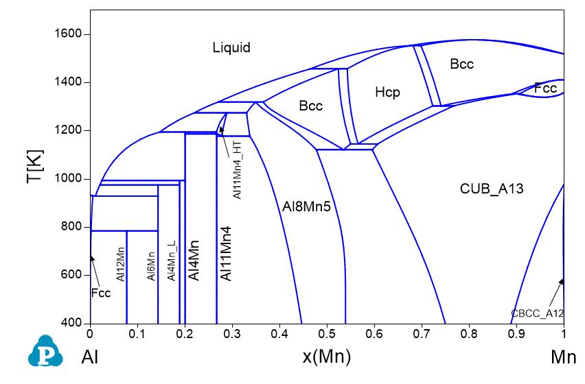
PDF Chapter 2 Alloys of the Al-Mg-Si-Fe System Al-Fe-Mg-Si PHASE DIAGRAM The phase composition of most wrought 6XXX-series alloys and of many casting alloys based on the Al-Si and Al-Mg systems (in particular, 356.0 and 512.0; Tables 2.1, 2.5, 2.7) can be analyzed using the Al-Fe-Mg-Si phase diagram. Alloys containing Mn are considered in Chapter 4.
Thermodynamics, kinetics and electronic properties of point ...
Experimental and Thermodynamic Studies of the Fe–Si Binary ... by I Ohnuma · 2012 · Cited by 70 — develop such practical materials, phase diagrams and ther- modynamic properties of Fe–Si base alloys are helpful and the calculation of phase diagrams ...
Part 6 Chemistry Engineering Department 23/10/ ppt download
THERMODYNAMIC MODELING OF PHASE COMPOSITION FOR Fe-Ca-Si ... carried out to plot the phase structure diagram of the Fe-Ca-Si-Al system as a modeling composition of the final alloy by the method of thermodynamic diagram analysis (TDA). TDA allows obtaining data for the system in the form of a phase diagram, each elementary subsystem in this diagram is independent. Subsystem can be regarded as a quasi-system.
Influence of Cu on modifying the beta phase and enhancing the ...
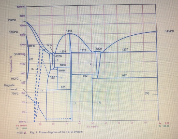
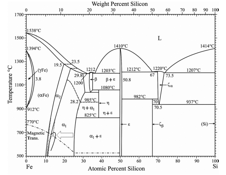
Thermo-Calc of the Phase Diagram of the Fe-Si System ... Part of the The Minerals, Metals & Materials Series book series (MMMS) Abstract In this work Thermo-Calc software was used to calculate the phase diagram of the Fe-Si system. The deduced phase diagram includes twenty fields, where three fields represent pure phases; two solid solutions and a liquid phase.
Fe-Si phase diagram [13]. | Download Scientific Diagram
PDF The Al-Si Phase Diagram - Buehler, an ITW Company The binary diagram is the starting point for developing more complex alloys and for understanding their behavior. Elements such as Si and Fe are common impurities found in aluminum alloys, but silicon is also a deliberate alloying addition in both cast and wrought Al alloys.

Characterization of the evaluation of the solid solubility of ...
Assessment of the ternary Fe-Si-B phase diagram ... The predicted metastable Fe-Si-B phase diagram, obtained by suspending the Fe 2 B phase, is shown in Fig. 7 for the isothermal section at 1000 °C. Download : Download full-size image; Fig. 7. Isothermal section of the metastable ternary Fe-Si-B phase diagram at 1000 °C.

Characterization of the Fe-rich corner of Al-Fe-Si-Ti ...
エリンガム図 / Ellingham diagram - Phase Diagram 金属やセラミックスの状態図、エンリンガム図などの情報を提供しています。 一部、不確かなものもありますので、自己 ...
Quiz On Phase Diagrams - ProProfs Quiz
Ternary Phase Diagrams - ASM International Chapter 10: Ternary Phase Diagrams / 195. Fig. 10.5 . Isopleth through hypothetical ternary phase diagram at a constant . 40% . C. adapted from ref 10.1. SPB Line. The single-phase boundary line is found on any section that . contains a single-phase region. The line is what its name implies. It is the boundary line around that single-phase region.

Phase equilibria in the Fe–La–Si ternary system - ScienceDirect
DIAGRAM OF EQUILIBRIUM PHASE COMPOSITION OF Fe - C - Si ... There has been constructed a diagram of the phase composition of the Fe - C - Si - B system and developed its mathematical model. It permits to determine its phase composition by the chemical composition of the initial mate- rial. There is also solved the inverse problem, i.e. the definition of the form and quantity of the initial furnace burden

File:Fe-P-phase-diagram-greek.svg - Wikimedia Commons
All Phase Diagrams - Polytechnique Montréal FactSage 8.1 - List of Stored Phase Diagrams (7811) FACT Databases. FToxid FACT oxide data (501) FTsalt salt data (351) FTmisc sulfide, alloy, micellaneous data (39) ... Ag-Fe-Si_1550C SGnobl: Ag-Ga FScopp: Ag-Ga FSlead: Ag-Ga FTlite: Ag-Ga SGTE 2020: Ag-Gd SGTE 2020: Ag-Ge BINS: Ag-Ge FScopp: Ag-Ge FTlite: Ag-Ge SGnobl: Ag-Ge SGTE 2014: Ag-Ge ...
Thermodynamic and kinetic analysis of the melt spinning ...
(PDF) [Easterling, Kenneth E.; Porter, Phase ... [Easterling, Kenneth E.; Porter, Phase Transformations in Metals and Alloys . × Close Log In. Log in with Facebook Log in with Google. or. Email. Password. Remember me on this computer. or reset password. Enter the email address you signed up with and we'll email ...
![Binary phase diagram of the Fe–Si system [6] indicating the ...](https://www.researchgate.net/publication/322812934/figure/fig1/AS:779410114355207@1562837260097/Binary-phase-diagram-of-the-Fe-Si-system-6-indicating-the-newly-introduced-phase-of.gif)
Binary phase diagram of the Fe–Si system [6] indicating the ...
Fe-Si - Phase Diagram - Google Search Phase Diagram. このサイトを検索 ... Fe-Si. Data from RICT-Sol alloy database ver.1.0. Sign in | Recent Site Activity | Report Abuse | Print Page | Powered By Google Sites ...

Melting experiments on Fe–Si–S alloys to core pressures ...
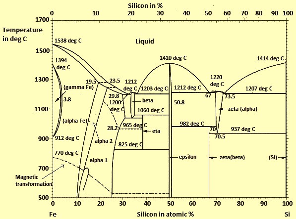
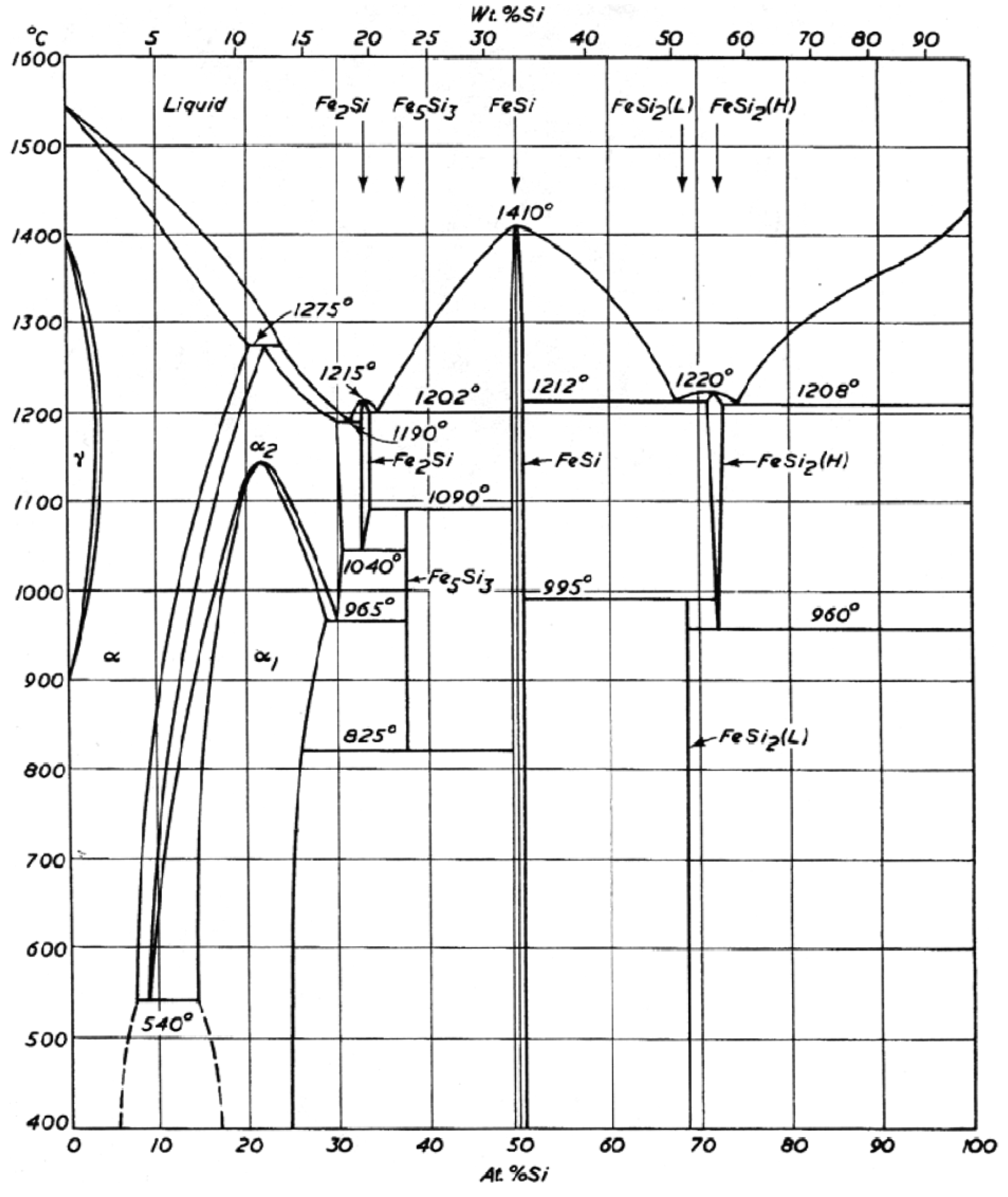
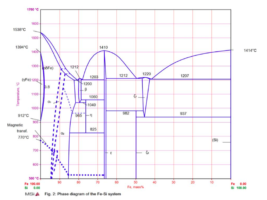
The Fe-Si phase diagram: from electrical steel to the planet ... The standard phase diagram for Fe-Si is the one by Kubaschewski (1982). In the iron-rich region, the dominant phases are a-Fe (0 at.%. Si), DO3 (a1, 25 at.%. Si) and B20 (e, 50 at.%. Si). a and a1 have the bcc lattice as underlying lattice, and a1 consists of an ordered replacement of one quarter of the Fe atoms by Si.
![Binary phase diagram of the Fe-Si system [31] | Download ...](https://www.researchgate.net/profile/Farah-Liana-Mohd-Redzuan/publication/333432142/figure/fig1/AS:910542218727424@1594101590354/Binary-phase-diagram-of-the-Fe-Si-system-31.png)
Binary phase diagram of the Fe-Si system [31] | Download ...
Fe—Si Iron—Silicon | SpringerLink Abstract. A set of interdependent thermodynamic values, consistent with the Fe-Si phase diagram, based on a critical assessment of all the published phase diagram and thermodynamic data has recently been submitted by Chart [1].
PHASE RELATIONS OF Mn-Fe-Si-C SYSTEMS
Phase Diagrams - an overview | ScienceDirect Topics Phase diagram: Phase diagram measurement was carried out by mixing concentrated JR400 solution and an anionic surfactant solution using deionized water in a 25 ml vial. All samples were put at 25 °C for at least one day. Then the appearance of each sample was checked visually. Viscosity measurement: The samples for phase diagram were used.

Assessment of the ternary Fe–Si–B phase diagram - ScienceDirect
PDF Chapter 1 Alloys of the Al-Fe-Mn-Si System A general view of the Al-Fe-Si phase diagram, the projections of the liquidus and solidus surfaces in the aluminum corner in the diagram are given in Figure 1.1. These data suggest that a decrease in the Hquidus and solidus temperatures (in Al-rich alloys) is primarily due to the concentration of sihcon, the effect of iron being much smaller.

Fe-Si phase diagram: the γ loop. For Si concentrations ...
PDF The iron-iron carbide (Fe-Fe3C) phase diagram Si Mn W Mo Review Fe-C phase diagram • 2 important points-Eutectoid (B): γ⇒α+Fe 3C-Eutectic (A): L ⇒γ+Fe 3C Fe 3 C (cementite) 1600 1400 1200 1000 800 600 400 0 12 3 4 5 66.7 L γ (austenite) γ+L γ+Fe 3C α+Fe 3C α + γ L+Fe 3C δ (Fe) C o, wt% C 1148°C T(°C) α 727°C = Teutectoid A R S 4.30 Result: Pearlite = alternating layers ...
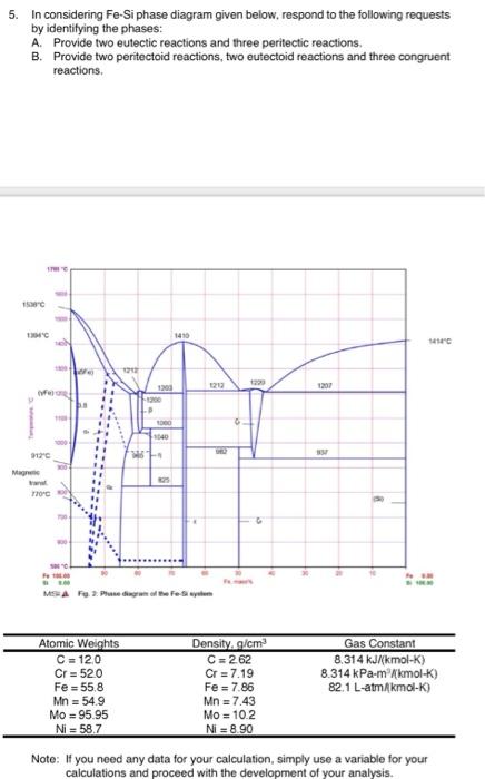
Solved 5. In considering Fe-Si phase diagram given below ...
Materials | Free Full-Text | Organometallic Routes into the ...
Instructions for the preparation of
Thermodynamic modeling of Al–Fe–V ternary system

Phase diagrams of the Fe-Si (b) and Fe-Si-Ni (a) systems with ...

Figure 2 from The FeSi phase diagram to 150 GPa | Semantic ...
Solved 5. In considering Fe-Si phase diagram given below ...
Chapter 8 Phase Diagrams
The Fe-FeSi phase diagram at Mercury's core conditions ...
BINARY (SGTE) Alloy Phase Diagrams
Solved 5. In considering Fe-Si phase diagram given below ...

Fe-Si Phase Diagram and Database (GeDb for FactSage)
The Fe-Si phase diagram: from electrical steel to the planet ...
![PDF] Assessment of the ternary Fe–Si–B phase diagram ...](https://d3i71xaburhd42.cloudfront.net/6d7e78e3f8f05fa511ab11788407d75a18da9b0b/17-Figure5-1.png)
PDF] Assessment of the ternary Fe–Si–B phase diagram ...
The Al-Rich Part of the Fe-Al Phase Diagram
Example E1: Stable and meta-stable phase diagram of Fe-C-Mn ...
0 Response to "41 fe si phase diagram"
Post a Comment