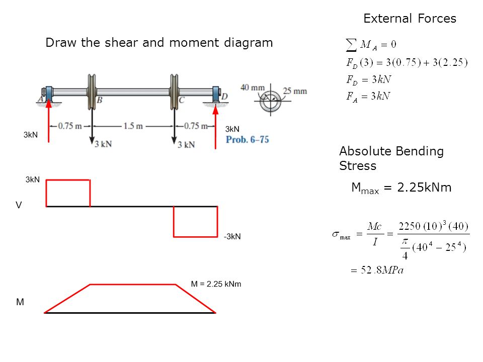
40 draw the shear diagram for the shaft.
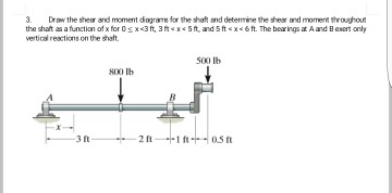
SOLVED:Draw the shear and moment diagrams for the shaft ... Problem 1 Easy Difficulty Draw the shear and moment diagrams for the shaft and determine the shear and moment throughout the shaft as a function of x for 0 ≤ x < 3 ft, 3 ft < x < 5 ft, and 5 f t < x < 6 f t. The bearings at A and B exert only vertical reactions on the shaft. Answer View Answer Discussion You must be signed in to discuss. SOLVED:Draw the shear and moment diagrams for the shaft ... Draw the shear and moment diagrams for the shaft (a) in terms of the paramet… 06:59 Both pulleys are fixed to the shaft and as the shaft turns with constant ang…
(Solution Download) Draw the shear and moment diagrams for ... (Solution Download) Draw the shear and moment diagrams for the shaft in. Draw the shear and moment diagrams for the shaft in terms of the parameters shown; there is a thrust bearing at A and a journal bearing at B. Units Used: kN = 103 N Given: P = 9kN a = 2 m L = 6 m
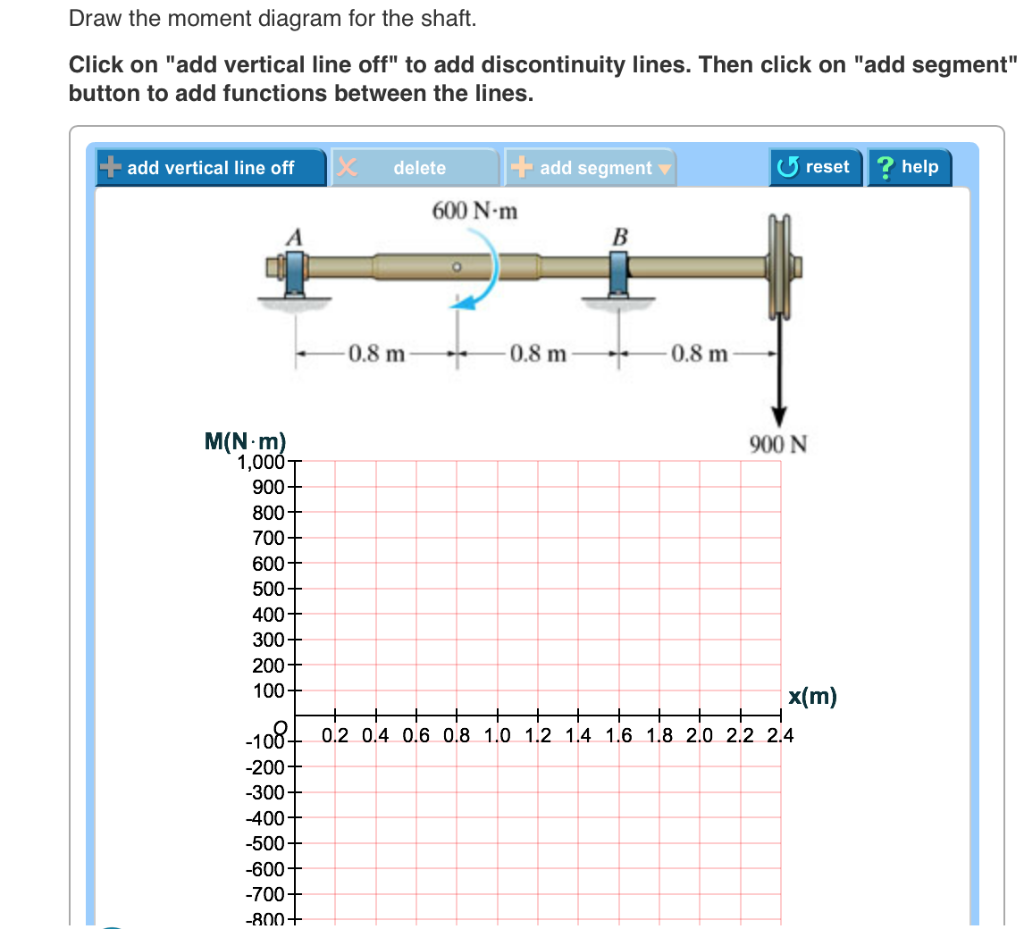
Draw the shear diagram for the shaft.
Online Engineering Calculators, formulas and Tools Free Circular Ring Moment, Hoop Load, and Radial Shear Equations and Calculator #20. Per. Roarks Formulas for Stress and Strain Formulas Section 9, Reference, loading, and load terms #20. Bulkhead or supporting ring in pipe, supported at bottom and carrying total load W transferred by tangential shear v distributed as shown. [Solved] Draw the shear and moment diagrams for the shaft ... Draw the shear and moment diagrams for the shaft in terms of Draw the shear and moment diagrams for the shaft in terms of the parameters shown; there is a thrust bearing at A and a journal bearing at B. Units Used: kN = 103 N Given: P = 9kN a = 2 m L = 6... Draw the shear and moment diagram for the shaft. The ... EngineeringMechanical EngineeringMechanics of Materials (10th Edition)Draw the shear and moment diagram for the shaft. The required diameter ( d ) of the shaft. Draw the shear and moment diagram for the shaft. The required diameter ( d ) of the shaft. Question Chapter 11.2, Problem 11.25P To determine
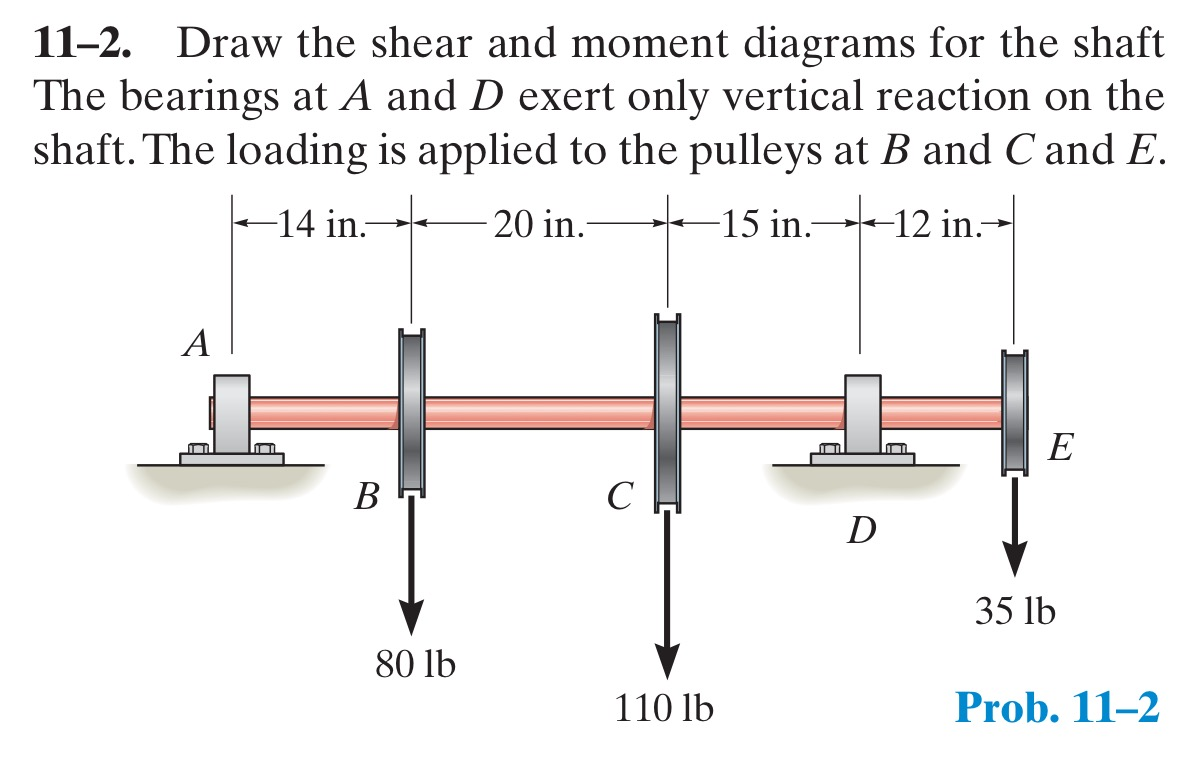
Draw the shear diagram for the shaft.. PDF Hibbeler Chapter 6 Part 1 (463-486) - Auburn University Draw the shear and moment diagrams for the shaft. The bearings at Aand Dexert only vertical reaction on the shaft.The loading is applied to the pulleys at Band Cand E. A B 14 in. 20 in. 15 in. 12 in. 80 lb 110 lb 35 lb C D E Ans: M(lb in) Lecture 2 - Shear and Bending Moment and Review of Stress 3. Draw the Shear, Normal, and Bending Moment Diagrams 4. Identify the critial locations, x along the structure where Vmax, Nmax, and Mmax exist. 5. Identify which stresses exist Normal Stress pure Shear Stress Transverse Shear Stress Normal Bending Stress Torsional Shear Stress pressure Vessel Stresses 6. SOLVED:The shaft is supported by a smooth thrust bearing ... All right. So for this question, we need to find the sheer bending moment diagrams as well as the maximum share, the maximum bending moment. Okay, So, by looking at our forces, we can create a free body diagram with all of our forces and our reaction force, as well as including our units and our dimensions. So from this three by diagram, we can calculate our reaction force f of beauty. [Solved] Draw the shear and moment diagrams for the shaft ... Draw the shear and moment diagrams for the shaft and determine the Draw the shear and moment diagrams for the shaft and determine the shear and moment throughout the shaft as a function of x for 0 ¤ x 3 ft, 3 ft x 5 ft, and 5 ft x 6 ft. The bearings at A and B exert only vertical reactions on the shaft.
SOLVED:Draw the shear and moment diagrams for the shaft ... Problem 10 Easy Difficulty. Draw the shear and moment diagrams for the shaft. The bearings at $A$ and $D$ exert only vertical reactions on the shaft. Answered: Problem A) A rod of mass M and length l… | bartleby Engineering Civil Engineering Q&A Library Problem A) A rod of mass M and length l moves across a frictionless surface with a speed v. It hits a stationary blob of mass m on one end of the board and sticks, causing the rod and blob to rotate as the systems continues traveling across the frictionless surface. Draw the shear and moment diagrams for the shaft in terms ... Draw the shear and moment diagrams for the shaft in terms of the parameters shown; There is a thrust bearing at A and a journal bearing at B. Units Used: kN = { 10 }^{ 3 } N. Given: P = 9 kN. a = 2 m . L = 6 m The Ultimate Guide to Shear and Moment Diagrams ... 4.0 Building Shear and Moment Diagrams. In the last section we worked out how to evaluate the internal shear force and bending moment at a discrete location using imaginary cuts. But to draw a shear force and bending moment diagram, we need to know how these values change across the structure.
Beams SFD and BMD - IIT Guwahati 0 + (area under the shear diagram from x 0 to x) If there is no externally applied moment M 0 at x 0 = 0, total moment at any section equals the area under the shear diagram up to that section When V passes through zero and is a continuous function of x with dV/dx ≠ 0(i.e., nonzero loading) BM will be a maximum or minimum at this point Solved Draw the shear diagram for the shaft if w = 500 ... Question: Draw the shear diagram for the shaft if w = 500 lb/ft, L = 10 ft. Click on "add vertical line off" to add discontinuity lines. Then click on "add segment" button to add functions between the lines. Note 1 - You should not draw an "extra" discontinuity line at the point where the curve passes the x-axis. Solved Draw the Shear and Moment diagrams for the shaft ... Draw the Shear and Moment diagrams for the shaft. The support at A is a journal bearing and at B its a thrust bearing. Question: Draw the Shear and Moment diagrams for the shaft. The support at A is a journal bearing and at B its a thrust bearing. (Book Solution) 6-1, Draw the Shear and Moment Diagrams ... (Book Solution) 6-1, Draw the Shear and Moment Diagrams for the shaft. The bearings at A and B exert only vertical reactions on the vertical shaft. - Bending, Mechanics of Materials, by R C Hibbeler. GATE preparations, Structure Mechanics and Analysis / By Sanjay Sharma / January 12, 2021 Problem: Draw the Shear and Moment Diagrams for the shaft.
[Solved] Draw the shear and moment diagrams for the shaft ... Draw the shear and moment diagrams for the shaft and determine the shear and moment throughout the shaft as a function of x for 0 ‰¤ x < 3 ft, 3 ft < x < 5 ft, and 5 ft < x < 6 ft. The bearings at A and B exert only vertical reactions on the shaft. Students also viewed these Sciences questions Draw the shear and moment diagrams for the shaft.
Answered: 11-1. Draw the shear and moment… | bartleby Solution for 11-1. Draw the shear and moment diagrams for the shaft. The bearings at A and Bexert only vertical reactions an the shaft. -N0 mm- 250 mim 24 kN
SIXTH EDITION ADVANCED MECHANICS OF MATERIALS - Academia.edu Academia.edu is a platform for academics to share research papers.
Solved Draw the shear and moment diagrams for the shaft ... Draw the shear and moment diagrams for the shaft and determine the shear and moment throughout the shaft as a function of x for 0 ≤ x ≤ 3 ft, 3 ft ≤ x ≤ 5 ft, and 5 ft ≤ x ≤ 6 ft. The bearings at A and B exert only vertical reactions on the shaft.
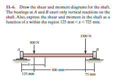
(Solved) - Draw the shear and moment diagrams for the ... Draw the shear and moment diagrams for the shaft. The bearings at A and B exert only vertical reactions on the shaft. Also, express the shear and moment in the shaft as a function of x within the region 125 mm 6 x 6 725 mm
Draw the shear and moment diagrams for the shaft. The ... Question: Mechanics of Materials - Instructor Solutions Manual [EXP-4667] Draw the shear and moment diagrams for the shaft. The bearings at A and D exert only vertical reaction on the shaft.The loading is applied to the pulleys at B and C and E. Step-by-Step Report Solution Verified Solution Scan the QR Code
Kelvin - Wikipedia A typical phase diagram. The solid green line applies to most substances; the dashed green line gives the anomalous behavior of water. The boiling line (solid blue) runs from the triple point to the critical point, beyond which further increases in temperature and pressure produce a supercritical fluid.
Draw the shear and moment diagrams for the shaft. The ... Draw the shear and moment diagrams for the shaft. The support at A is a journal bearing and at B it is a thrust bearing. Given: F = 200 Ib\quad w = 100 \frac { Ib }{ ft } \quad M = 300 Ib.ft\quad a = 1 ft\quad b = 4 ft\quad c = 1 ft
Answered: draw the shear and moment diagram of… | bartleby A: Equivalent resultant force Systems of equal force. The underlying principle is that two force…. question_answer. Q: Draw the shear and moment diagrams of the beams shown using the area method. 30 kN 9 kN/m A B 3m 2m.
Draw the shear and moment diagrams for the shaft. 1 Answer to Draw the shear and moment diagrams for the shaft. The bearings at A and B exert only vertical reactions on the shaft. Also, express the shear and moment in the shaft as a function of x within the region 125 mm 6 x 6 725 mm
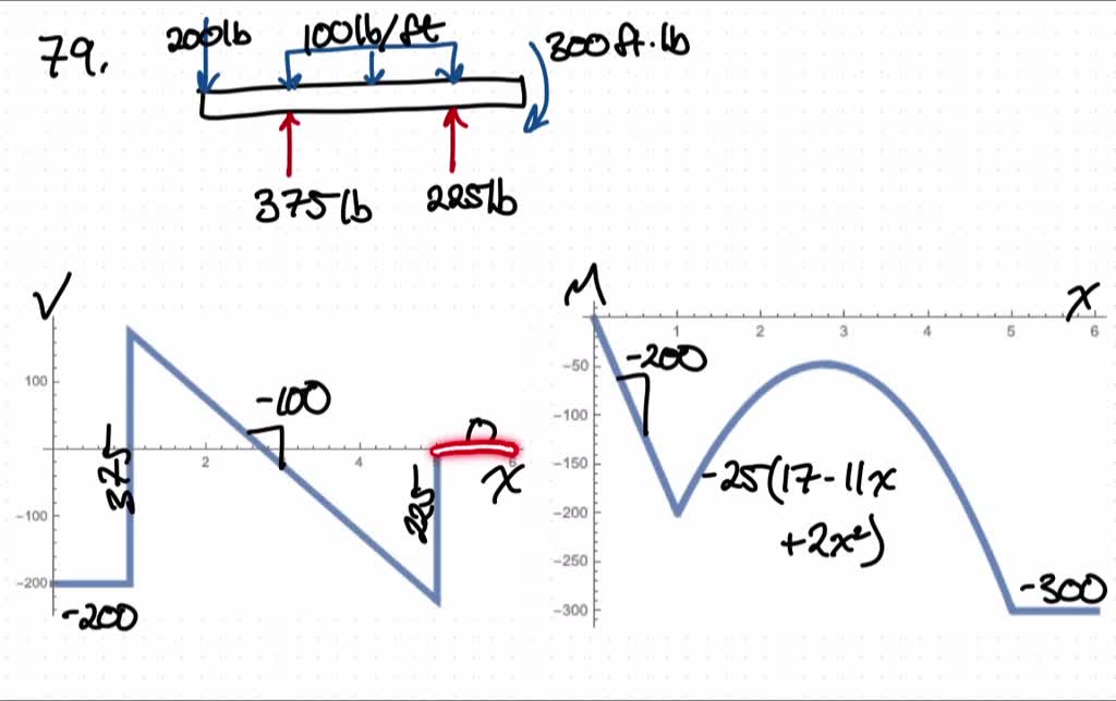
draw the shear and moment diagrams for the shaft the bearings at a and d exert only vertical reactio
How to Draw Shear Diagrams | ReviewCivilPE This is the first point of data, draw a line from zero to negative 10. Continuing on the next force is 21.67 lb upward at the A support. Extend the line horizontally until it is at A and then add the 21.67 force to it. The shear diagram is now at 11.67 lb on the positive side. The next force is -10 lb.
Solved 6-6. Draw the shear and moment diagrams for the ... 6-6. Draw the shear and moment diagrams for the shaft The bearings at A and B exert only vertical reactions on the shaft. Also, express the shear and moment in the shaft as a function of x within the region 125 mm
(Solved) - Draw the shear and moment diagrams for the ... Draw the shear and moment diagrams for the shaft and determine the shear and moment throughout the shaft as a function of x for 0 … x 6 3 ft, 3 ft 6 x 6 5 ft, and 5 ft 6 x 6 6 ft. The bearings at A and B exert only vertical reactions on the shaft. Jul 14 2021 04:24 PM 1 Approved Answer Naveen g answered on July 16, 2021 5 Ratings, ( 9 Votes)
Solved Draw the shear diagram for the shaft if P = 9 kN, a ... Draw the shear diagram for the shaft if P = 9 kN, a =2 m, L=6 m. Click on "add vertical line off to add discontinuity lines. Then click on "add segment" button to add functions between the lines. + O 8 ? B No elements selected V (kN) 8 6 4 2 0+ 0 1 (m) 3 4 5 6 -2+ -6 -8 Draw the moment diagram for the shaft if P = 9 kN, a = 2 m, L=6 m Click on "add
PDF 6-1. Draw the shear and moment diagrams for the shaft.The ... Draw the shear and moment diagrams for the beam, and determine the shear and moment throughout the beam as functions of x. 2 kip/ft 8 kip x 10 kip 40 kip ft A 30 kip ft B 5 ft 5 ft 2 kip/ft 5 ft 6-19. Draw the shear and moment diagrams for the beam. 06 Solutions 46060_Part1 5/27/10 3:51 PM Page 338 347
PDF HW 19 SOLUTIONS - University of Utah Draw the shear and moment diagrams for the beam. 2 kip 2 kip 2 kip 2 kip Kip) M(Kp-ft) 6—1. Draw the shear and moment diagrams for the shaft.The hearings at A and B exert only vertical reactions on the shaft. V(XN) 800 mm 250 mm 75 24 kN . 6-10. The engine crane is used to support the engine,
Draw the shear and moment diagram for the shaft. The ... EngineeringMechanical EngineeringMechanics of Materials (10th Edition)Draw the shear and moment diagram for the shaft. The required diameter ( d ) of the shaft. Draw the shear and moment diagram for the shaft. The required diameter ( d ) of the shaft. Question Chapter 11.2, Problem 11.25P To determine
[Solved] Draw the shear and moment diagrams for the shaft ... Draw the shear and moment diagrams for the shaft in terms of Draw the shear and moment diagrams for the shaft in terms of the parameters shown; there is a thrust bearing at A and a journal bearing at B. Units Used: kN = 103 N Given: P = 9kN a = 2 m L = 6...
Online Engineering Calculators, formulas and Tools Free Circular Ring Moment, Hoop Load, and Radial Shear Equations and Calculator #20. Per. Roarks Formulas for Stress and Strain Formulas Section 9, Reference, loading, and load terms #20. Bulkhead or supporting ring in pipe, supported at bottom and carrying total load W transferred by tangential shear v distributed as shown.









0 Response to "40 draw the shear diagram for the shaft."
Post a Comment