38 5 wire ceiling fan capacitor wiring diagram
Amateur wiring diagram (X's are wire nuts): http://imgur.com/F6V7C8L Pics of fan assembly: http://imgur.com/a/Lr9tq The instructions say to attach the ceiling fan light to a white (or gray) wire and a blue (or red) wire. The wires should be labeled "for light". My ceiling fan assembly has one free white wire labeled "for light" coming from the pull chain but no red or blue wire labeled "for light". There is another white wire labeled "for light"; this is attached to a black wire which leads i... Collection of hampton bay ceiling fan capacitor wiring diagram. A wiring diagram is a streamlined standard photographic representation of an electric circuit. It reveals the components of the circuit as simplified forms, and also the power as well as signal connections in between the gadgets.
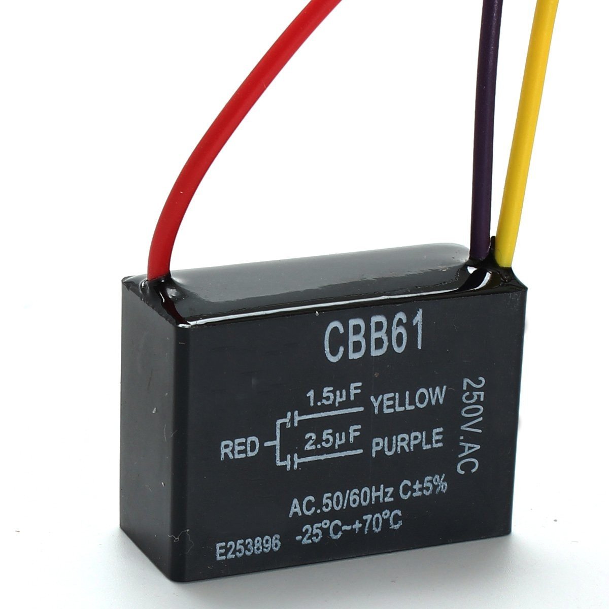
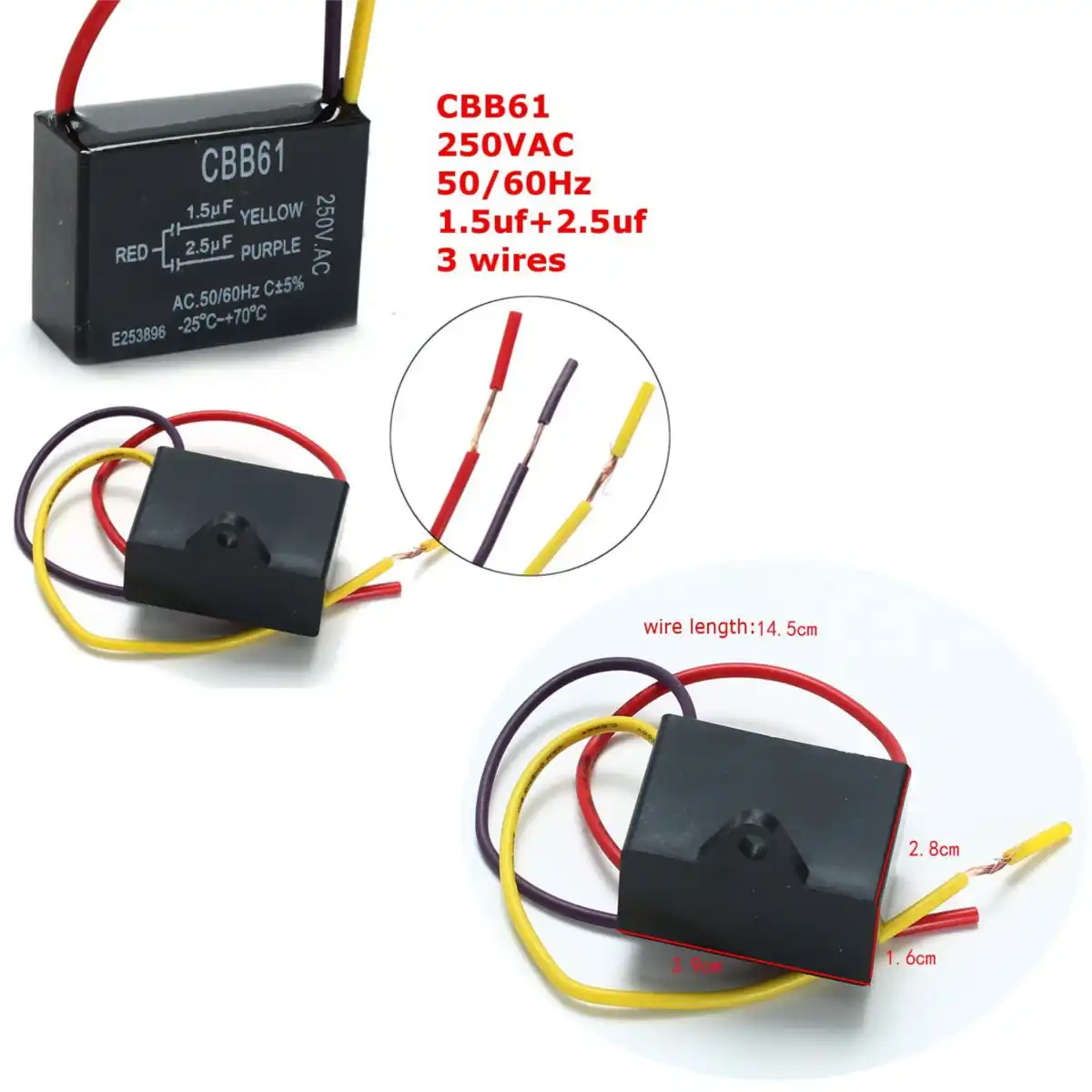
As i shown in the above ceiling an 3 wire capacitor diagram that red is common wire and yellow for microfarad and Purple for farad. However IN SHA ALLAH in further post i will explain the fan 5 wire capacitor, regulating speed switch diagram and replacement of fan capacitor in fan motor. Dec 28, · Generic 3-speed reversible spinner wiring diagram.
5 wire ceiling fan capacitor wiring diagram
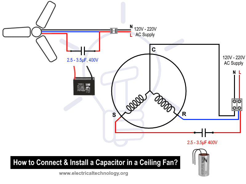
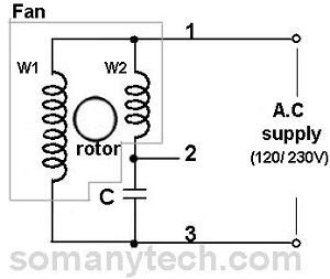
In ceiling fan we have 3 wire coming from winding , which know with name of common, start and run. The common wire will be connect direct to power supply, running will connect to capacitor and supply and starting wire will be connect to other terminal of capacitor. Now if you buy the same value capacitor then replace the capacitor as the old ... Hampton Bay Ceiling Fan Capacitor Wiring Diagram from i0.wp.com. Print the cabling diagram off plus use highlighters in order to trace the circuit. When you make use of your finger or the actual circuit together with your eyes, it is easy to mistrace the circuit. A single trick that We use is to print a similar wiring plan off twice. 3 Wire ceiling fan capacitor instillation with speed controller switch 3 wire ceiling fan motor capacitor diagram 5 wire fan motor capacitor diagram and explanation I hope now you will completely understood the replacing capacitor in ceiling fan motor or other fan, however if you have any question regarding this post then ask me comment section.
5 wire ceiling fan capacitor wiring diagram. Ceiling fan wiring diagram 1: Black speed switch, three wire capacitor . Speed Switch connection table: 0 (OFF) : NC 1 (Fast): 1 to L and C1-1 2 (Med) : 1 to L and C1-2 3 (Slow): 1 to L , C1-1, and C1-2 . Ceiling fan wiring diagram 2: Black speed switch with only three terminals connected, two wire capacitor . Content warning: Gore In this chapter: Tag your goddamn pomegranates Next chapter: 'The Joys of Air-Braking, by Franz Reichelt' Fun trivia fact: While this is not the worst day Ajax has ever had yet, it's definitely in the top 25. After next chapter, that bumps up to be a contender for the top 10. [Hardwired series homepage](https://www.reddit.com/r/HFY/wiki/series/hardwired) [Previous Chapter](https://www.reddit.com/r/HFY/comments/7s491o/oc_hardwired_interrogative_inertia_chapter_25/) **C... This is a simple illustrated circuit diagram of ceiling fan.To be noted that the wiring diagram is for AC 220V single phase line with single phase ceiling fan motor. Here a simple SPST switch is used to supply power or not to the fan motor and a Regulator is used to controlling the fan speed. 04.10.2016 · 3) Cut the blue wire and splice the fan side blue wire to the thick white wire. This grounds out the up flow control. 4) for white ( for light ) wires, leave as is and connect to light kit white wire. 5) For blue ( for light ) wire, cut from puck. a. Connect cut blue wire to one side of pull chain switch. b.
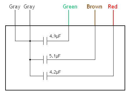
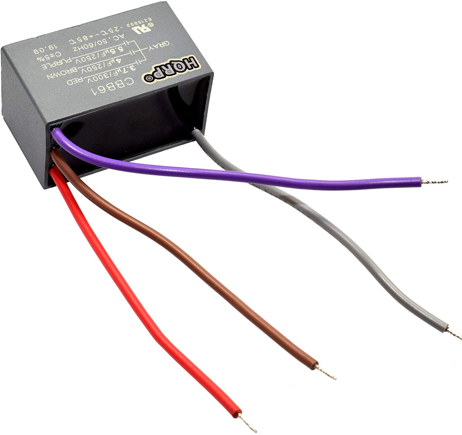
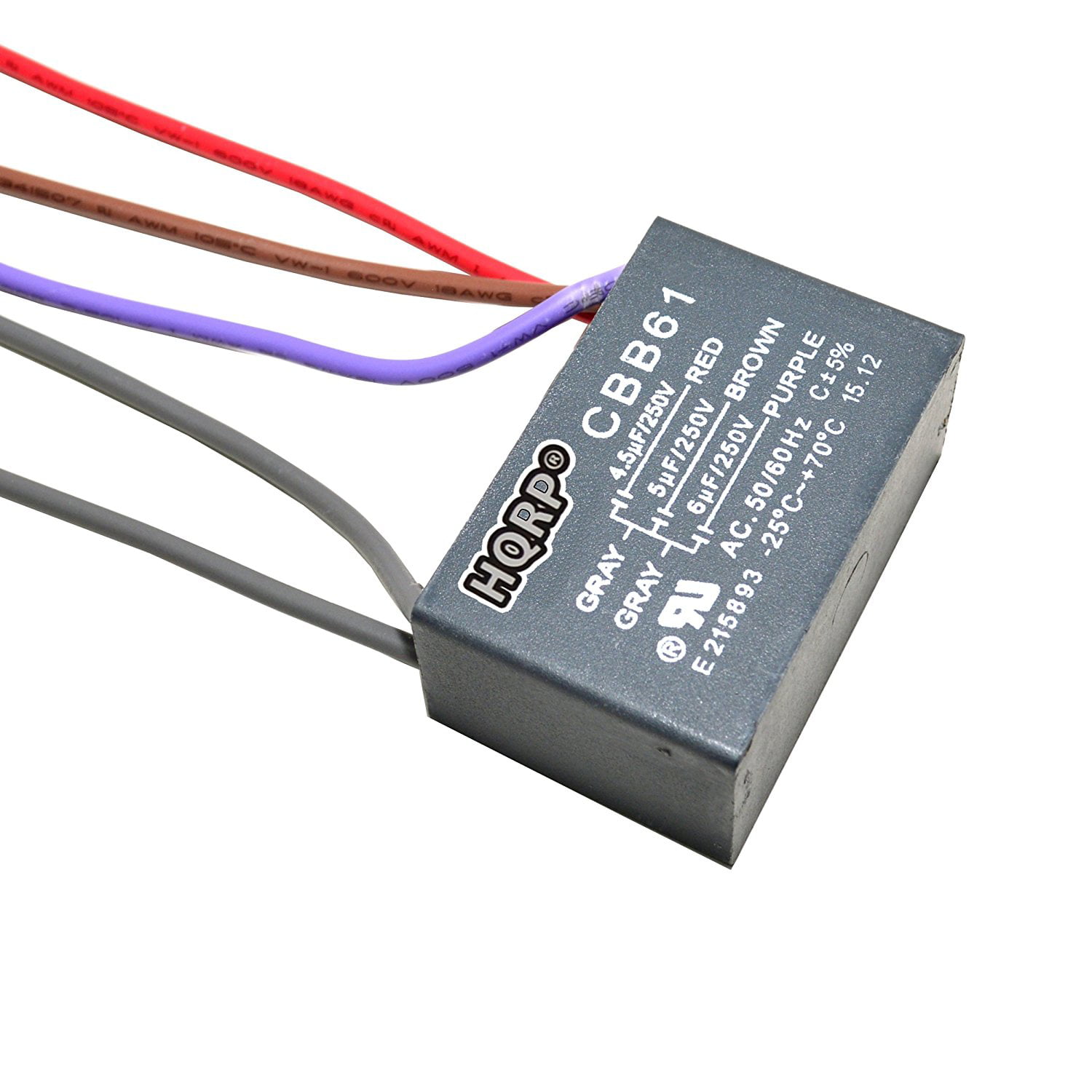
Hampton Bay Ceiling Fan Wiring Colors Receiver. Free hampton bay reva7067b ceiling fan wiring diagram hqrp capacitor for fits garrison 2 pack motor 5uf 4uf 3 wire sd switch repair compatibility guide 4 6uf 5 and manuals when i opened the reverse cbb61 7uf troubleshooting st regis commercial electric antique kit 887774403032019 7728600 westinghouse distributors control cfpo capacitors fans 6 ... Ceiling Fan Capacitor 4 or 5 Wire 4/4.5/5. Ceiling fan replacement capacitor. This is a combined capacitor with three capacitors built into one package. The capacity is 4uf + 4.5uf + 5uf. Please note: Both grey wires can be joined/combined together to make this work as 4 wire capacitor. Harbor breeze ceiling fan wiring fans 3 sd switch diagram site resource hqrp capacitor for 4 5uf 6uf 5 wire plus 12 methods to give you good lighting and coolness warisan compatibility guide ceilingfanswitch com 1uf 2uf coaster repair cbb61 2 parts fits 7uf 4uf receiver replacement doityourself community forums remotes more hampton bay dual triple in the… Read More » 12+ Ceiling Fan Capacitor Wiring Diagram. Sistemas de arranque de compresores en refrigeracion 120 vac y 220 vac en general. Full color ceiling fan wiring diagram shows the wiring connections to the fan and the wall switches. We must connect the capacitor in series with the starting winding and then it connected across the power supply.
06.04.2017 · American Wire Gauge: BLAC: Brushless AC: BLDC: Brushless DC: BLDM: Brushless DC Motor: C: Capacitance: CKT: ... CH is also used to label Ceiling Height. Reply. Vishal says: October 8, 2019 at 7:21 am Electriocn full from. ... Why Capacitor Used in Fan or Motor : How to Explain. Inductor Questions and Answers Basics. 30.08.2012 · I was then told to try the capacitor and contactor to the condenser ... blower shuts off. The first issue after install was the heat (probably just the blower) would not work. After checking wiring diagram, I found the wiring on fan relay were ... You could also try removing the G green wire from the thermostat and see if the fan ... I am looking to bypass the remote control on my Harbor Breeze Ceiling fan. Based on a few other threads I have read on here it seems like I am on the right track. However, I want to make sure I didn't miss anything. I plan on cutting out the (9) port plug connecting the (3) wires exiting the fan/light bundle, and the hot and neutral shaft runs; to the remote receiver; and directly connection the (3) wires from the fan/light bundle to the (3) wires from the box. (the ground wires in the box... Aug 29, 2016 — hook up 5-wire fan capacitor I need to know which colored wires ... I need a basic wiring diagram for a 3spd, 3 wire capacitor ceiling fan ...
5 Wire Ceiling Fan Capacitor Wiring Diagram - 5 wire ceiling fan capacitor wiring diagram, Every electrical structure consists of various distinct pieces. Each component should be placed and connected with different parts in specific way. Otherwise, the structure will not work as it should be.
Ill make this short. Ceiling fan went to crap. Buzzing, wont move. I'm sure its the capacitor. So I found a capacitor that will work with what I currently have. 7uf+6.5uf+6.5uf 250v. But, the wiring diagram looks different from the new. How do I wire the new capacitor? I've attached an image for reference. http://imgur.com/a/flbnn
21 Posts Related to 5 Wire Ceiling Fan Switch Wiring Diagram. ... Ceiling Fan 2 Wire Capacitor Wiring Diagram. Ceiling Fan 3 Wire Capacitor Wiring Diagram. Ceiling Fan Wiring Diagram 5 Wire Capacitor. Ceiling Fan 3 Speed Switch Wiring Diagram. Ceiling Fan Dimmer Switch Wiring Diagram.
Here's a picture of what came out of the fan: http://i.imgur.com/KH0Ub4W.png Mom's ceiling fan, pull switch is broken, molded capacitor block has experienced meltdown. Looking at the fan switch diagram found online,(http://i.imgur.com/YydpRXx.gif) it seems that position 3 is off (since the black wire T2 to ground measured 120v). The bad capacitor block shows 330k ½w (?½watt?) resistors in parallel to each capacitor (6µF & 8µF). I am unable to locate any capacitors for sale online that sho...
Ceiling Fan Wiring Diagram 5 Wire Capacitor. September 12, 2019 by admin. 21 Posts Related to Ceiling Fan Wiring Diagram 5 Wire Capacitor. Ceiling Fan 2 Wire Capacitor Wiring Diagram. Ceiling Fan 3 Wire Capacitor Wiring Diagram. Ceiling Fan Wiring Diagram Capacitor.
Ceiling Fan Connection With Capacitor Within Ceiling Fan Wiring Diagram With Capacitor ... Solucionado: como instalar un motor trifasico de 5 caballos.
5 wire ceiling fan capacitor wiring diagram - You will want an extensive, expert, and easy to comprehend Wiring Diagram. With this sort of an illustrative manual, you are going to be able to troubleshoot, prevent, and total your tasks without difficulty.
2137 products — 2.5uf fan ceiling fan wiring diagram capacitor cbb61. $0.12-$0.15/ Piece. 1 Piece(Min. Order).
i need a color code wiring diagram to install a5 wire capacitor in a 52 in. model 5745 ceiling fan.the fan was bought from walmart and has no brand name on it.the only other info tag has upc#7-59590-21091-6 and a 1-xxx-xxx-xxxx for service.the original cap.was removed leaving no trace of wire positions.new cap.has 5 wires 2 yellow on one end and red 4uf,blue 5.5 uf,purple 6uf on the other end ...
15 Ceiling Fan 2 Wire Capacitor Wiring Diagram. Note that the refrigerator compressor terminals start, run and common finding method is same because. With the below wiring diagrams, you can install 90% of ceiling fans, no matter the make or model. These motors have the electrical device. This wiring diagram shows the power starting at the ...
how to replace a capacitor in a ceiling fan 3 ways. Architectural wiring diagrams performance the approximate locations and interconnections of receptacles, lighting, and long-lasting electrical facilities in a building. Interconnecting wire routes may be shown approximately, where particular receptacles or fixtures must be upon a common circuit.
5 wire ceiling fan capacitor wiring diagram - You will want an extensive, expert, and easy to comprehend Wiring Diagram. With this sort of an illustrative manual, you are going to be able to troubleshoot, prevent, and total your tasks without difficulty.
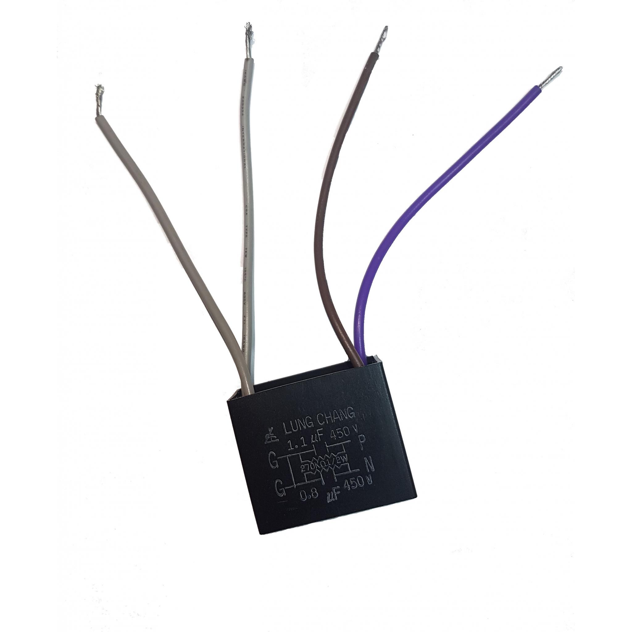
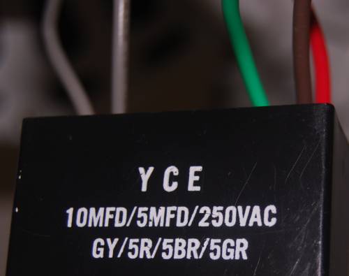
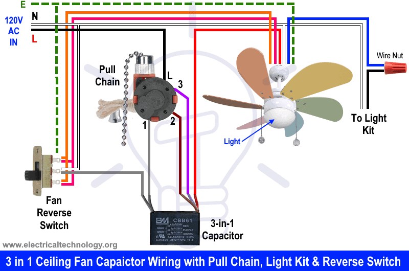
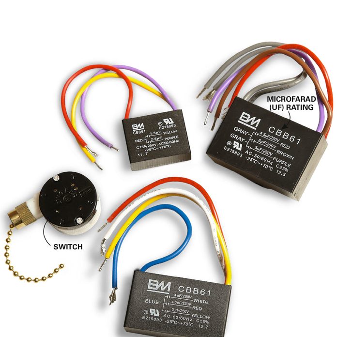
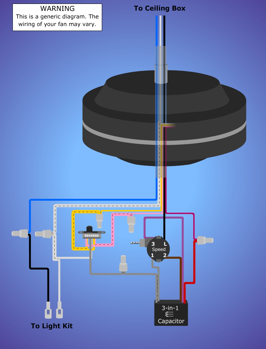
5 Wire Ceiling Fan Capacitor Wiring Diagram. In ceiling fan we use the 5 wire capacitor for speeds, low Med and High speed. On this type of capacitor we have five wire in which two is common and 3 other for different value capacitance micro farad. In the below diagram i shown a 5 wire fan motor capacitor with it;s capacitor diagram.
4 Wire Ceiling Fan Capacitor Wiring Diagram New Unique Wiring, size: 800 x 600 px, source: thoritsolutions.com. Whatever you are, we aim to bring the content that matches just what you are looking for. You may originate from an internet search engine, after that discover this site. This topic is a lot of individuals looking on the internet, as ...
Ceiling Fan 3-Wire Capacitor Wiring Diagram from 1.bp.blogspot.com. Effectively read a electrical wiring diagram, one has to find out how the particular components inside the program operate. For instance , if a module is powered up also it sends out a signal of 50 percent the voltage and the technician would not know this, he would think he ...
Assortment of hunter ceiling fan capacitor wiring diagram. A wiring diagram is a streamlined traditional photographic depiction of an electric circuit. It shows the components of the circuit as streamlined shapes, and also the power and also signal connections in between the gadgets.
Assortment of hunter ceiling fan wiring diagram with remote control. well as control the lights of the ceiling fan with on off and dimming options, ceiling fan circuit type 2 canarm black speed switch with only three terminals connected two wire capacitor notes speed switch connection table, if you look at this particular ceiling fan wall switch it looks like a remote Appliance …
5 Wire Ceiling Fan Capacitor Wiring Diagram - 5 wire ceiling fan capacitor wiring diagram, Every electric arrangement consists of various diverse components. Each component should be set and connected with different parts in specific manner. If not, the structure will not function as it ought to be.
This capacitor worked great for my fan. The colors of the wires weren't exactly the same (this has 2 grey) but after looking at the schematic I saw it would ...Batteries Included?: NoColor: Black Rating: 4.4 · 578 reviews
Ceiling Fan Capacitor 5 Wire for Compatible with NEW TECH Harbor Breeze 4.5uf 6uf 6uf 50/60Hz AC 250V CBB61. 4.5 out of 5 stars. 298. $5.99. $5. . 99. This ceiling fan capacitor is a great way to add some additional durability to your ceiling fan. This ceiling fan capacitor is a great way to add some additional durability to your ceiling fan.
The fan wires go like this. An Introduction of HQRP Capacitor for Harbor Breeze Ceiling Fan: If you are looking for a Harbor Breeze ceiling fan capacitor here it is. The price of this replacement part is $ and ASIN number of the item is B01B4MF6H4. The pattern of this replacement part is uf+5uf+6uf 5-Wire with tolerance .
At MOTOR CAPACITOR WIRING GUIDE we show how to hook up a typical capacitor. In the partial wiring diagram above, the compressor (COMP) ... (mod) - My ceiling fan will run if I push it to get it ... - a loose wire connection - bad switch - failing fan motor. On 2020-01-21 by Don. My ceiling fan will run if I push it to get it going, but won't ...
After getting wiring diagram off internet it was diagnosed as freezer stuck in ... but fan running. Turned gray knob on defrost timer (located bottom left back of freezer) past defrost position to ... Installed new one in reverse order. Then removed wire bail holding run capacitor to compressor plug assembly, removed run capacitor, plugged ...
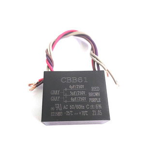
In the above diagram i shown an image of fan motor capacitor which CBB61 and it's a 5 wire capacitor, the two gray wire are common and red is uF V and Brown is 6 uF Volts and Purple is 5 micro farad and V. CBB61 uf/6uf/6uf 5 wire capacitor Deals of the Day · Read Ratings & Reviews · Fast Shipping · Shop Our Huge Selection2,,+ followers on ...
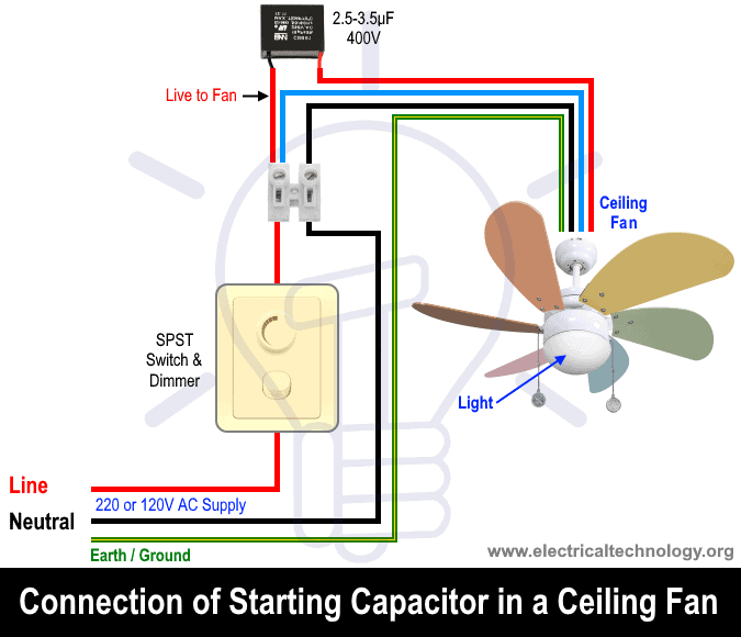
How to wire and replace a ceiling fan capacitor? Start Capacitor installation in a ceiling fan. 3-in-1 ceiling fan Capacitor wiring diagram.
products Tags: Wholesale Electric Fan Capacitor Ceiling Fan Wiring Diagram Capacitor Cbb61 Fan Capacitor | Wholesale Ccb61 Capacitor Super. Turn off the power to the ceiling fan at the circuit breaker panel before proceeding The replacement start/run motor capacitor type CBB61 was identical to the blown Ceiling fan motor capacitors can have two (2) to five (5) wires in different .
Fan with 3 wires (as seen from fan side with capacitor) 4 wire fan with inbuilt LED light; Considering all the above facts, we have created a ceiling fan wiring diagram guide for ease of installation process. Based on countries and their wiring code there are two major classifications. Table of wiring code in different countries:
25.05.2021 · I couldn't find a wiring diagram for the specific fan (and capacitor, which has 4 wires) ... red capacitor wire (3.5µF, 200V) goes to switch terminal 3; yellow capacitor wire (6µF, ... Wiring a ceiling fan and light switch with two three-cable wires. 2.
3 Wire ceiling fan capacitor instillation with speed controller switch 3 wire ceiling fan motor capacitor diagram 5 wire fan motor capacitor diagram and explanation I hope now you will completely understood the replacing capacitor in ceiling fan motor or other fan, however if you have any question regarding this post then ask me comment section.
Hampton Bay Ceiling Fan Capacitor Wiring Diagram from i0.wp.com. Print the cabling diagram off plus use highlighters in order to trace the circuit. When you make use of your finger or the actual circuit together with your eyes, it is easy to mistrace the circuit. A single trick that We use is to print a similar wiring plan off twice.
In ceiling fan we have 3 wire coming from winding , which know with name of common, start and run. The common wire will be connect direct to power supply, running will connect to capacitor and supply and starting wire will be connect to other terminal of capacitor. Now if you buy the same value capacitor then replace the capacitor as the old ...










0 Response to "38 5 wire ceiling fan capacitor wiring diagram"
Post a Comment