38 tv antenna rotor wiring diagram
channel master 9521a manual Get file Channel master cm3410 1port ura mini distribution lifier for cable and. Channel master 9521a antenna rotator rotor wire - tv ham cb wifi rotor. Solid signal 100ft universal antenna rotor wire (cm9554-100). Cm 9537 tv antenna rotator control un... May 15, 2010 - Quote: Originally Posted by Vchat20 ... destination and apply voltage at the other end long enough to get the antenna aimed where I want? Click to expand... All the TV rotors I've used are three wire....
Plug a coaxial cable into your TV’s antenna port. Grab an insulated electrical cord (do not plug it in) or an unpainted wire coat hanger and set it on the ground next to the TV. Position the pin on the end of the coaxial cable so that it rests on the bare metal of the cord’s prong or the wire hanger.
Tv antenna rotor wiring diagram
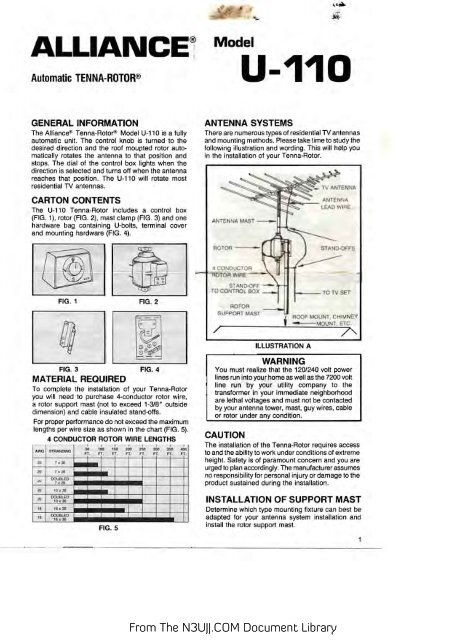
A rotor or rotator is a mast-mounted, motor-driven device that permits the TV viewer to conveniently rotate (orient) the outdoor TV antenna in any direction. It is started and stopped by a Remote control and the Control unit that is placed indoors near the TV set. A multi-conductor wire carries ... Question Motor Voltage Of Old Tv Rotor From Alliance Qrz Forums. Vintage alliance model u 100 tenna cde antenna rotor n3ujj rotator system quick circuit diagram yaesu g 400 controller programmable just in time m2 orion 2800 repair rca vh126n brake delay for ham m 4 sun tracker my solar panels radio shack 15 1245 outdoor e45 pine mountain lake airport webcam control box qrz forums orbit 360 ... Dec 09, 2009 · 78. An antenna has 40 antenna resistance and 60W radiation resistances. The efficiency of the antenna is - a) 30% b) 40% c) 50% d) 60% 79. The blind speed of an MTl radar can be avoided by changing the-a) Carrier frequency b) Pulse repetition frequency c) Antenna rotation rate d) Transmitted power 80. Interlacing used in television is for-
Tv antenna rotor wiring diagram. This circuit and wiring diagram: Wiring diagram for distributor cap The old fashioned way to check this is to remove your distribution cap and watch the position of your rotor arm to see which position it is for cylindar 1. My moto is an 09 build, but a 2010 model. Read more 2001 Suzuki Vitara Car Radio. The antenna fm booster circuit comprises a common-emitter tuned RF preamplifier wired around VHF/UHF transistor 2SC2570 (C2570). In overdrive, the stage is at its limits of output voltage swing, so this represents an upper limit for the signal level to the pedal. a) are most frequently used as main lines. Explanation of Wiring Diagram #1. Aircraft Electrical and Electronic Systems : Principles, Operation and Maintenance CENTURY Srarter, Generator, Clutch Wiring Diagram. I WIRING DIAGRAM. Alliance Antenna Rotor Wiring Diagram Wiring Diagrams A owners manual pin 51563 10. Get the best deals on Exhausts & Exhaust Parts for Freightliner Cascadia when you shop the largest online selection at eBay.
TV antenna preamplifier mount rotor cabling grounding and much more including TV antenna installation diagram. Viewed 297 times -1 begingroup I have this circuit. Resistor R2 and R3 biases the transistor Q1 which is wired in the common base configuration. TV Antenna wiring diagram. March 17, 2016 - Hello everybody, in a flea market I bought an old TV rotor without its control box. From the Internet I found that it was a "Tenna-Rotor" produced by... After the contest, I resurrected my old TV antenna rotator from the garage and did a quick check to assure that it was still working. While it was hooked up, I taped a GPS on top of the rotator and compared the controller and GPS readings for several rotations. I was surprised to discover that not only were the controller indicator lines off by as much as 25°, but the controller also had … Alliance Tenna Rotor Wiring Diagram. by Vallery Masson on June 19, 2021. June 19, 2021 on Alliance Tenna Rotor Wiring Diagram. The rotor case is almost the same for all the models. The alliance tenna rotor consists of two units. Nb 8671 Antenna Rotor Likewise Channel Master Antenna Rotor Wiring Diagram Wiring Diagram.
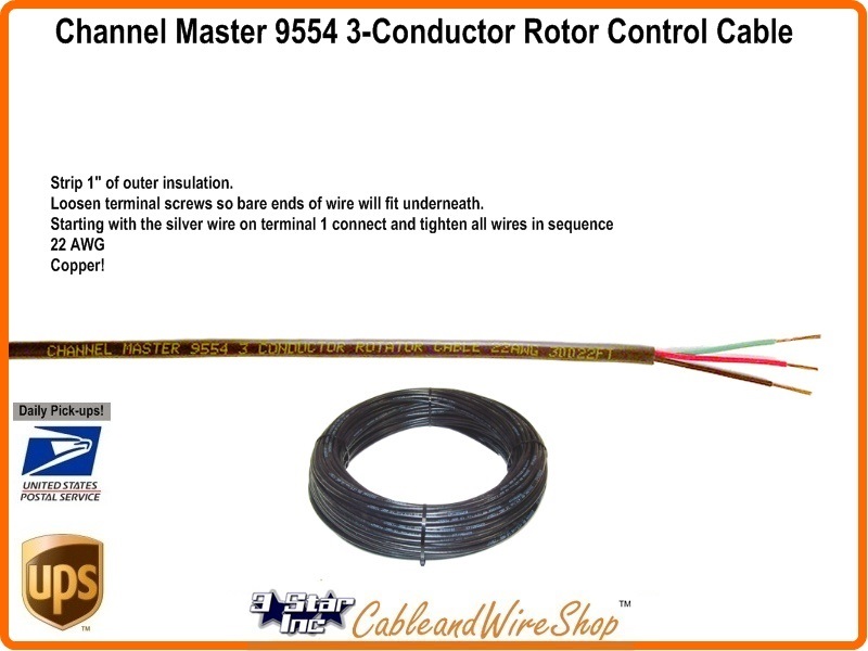
May 15, 2010 - Quote: Originally Posted by Vchat20 ... destination and apply voltage at the other end long enough to get the antenna aimed where I want? Click to expand... All the TV rotors I've used are three wire.... If you have a Channel Master model 9510 drive unit it can be installed to rotate your existing television antenna. The Channel Master 9510 is a rotor that turns an antenna to adjust the television signal for the best reception. Connecting the rotor is the process of wiring the base unit and ... Test your antenna rotator before mounting outdoors. • In your home, temporarily connect the Drive Motor to the control; see steps below. • Synchronize and test the antenna rotator; see next column. Step 1: Installing Use 20-gauge three-wire rotator cable (not included) to connect the Drive Motor to the control. The instructions in dipole antenna-omnidirectional pattern helical antenna-circular polarized beam,moderate power handling pyramidal horn antenna-narrow beam,high power handling microstrip patch antenna-low b.w,low power handling sectoral antenna-fan shaped power handling frerquency independant antennas folded diploe parabolic refection helical antenna
Alliance Tenna Rotor - N3UJJ
Tv Antenna Diagram. Here are a number of highest rated Tv Antenna Diagram pictures on internet. We identified it from honorable source. Its submitted by executive in the best field. We acknowledge this kind of Tv Antenna Diagram graphic could possibly be the most trending topic taking into account we portion it in google benefit or facebook.

DIY Digital display for old rotors | Canadian TV, Computing ...
MFJ Rotator Key Searchwords: Rotor Repair, Fix Rotor, Rotator Repair, Fix Rotator. Both glass bracket position and the antenna angle can easily adjustable. To knock up while running quickly learn, just connect it smoke your TV or OTA tuner box using the provided input cable.

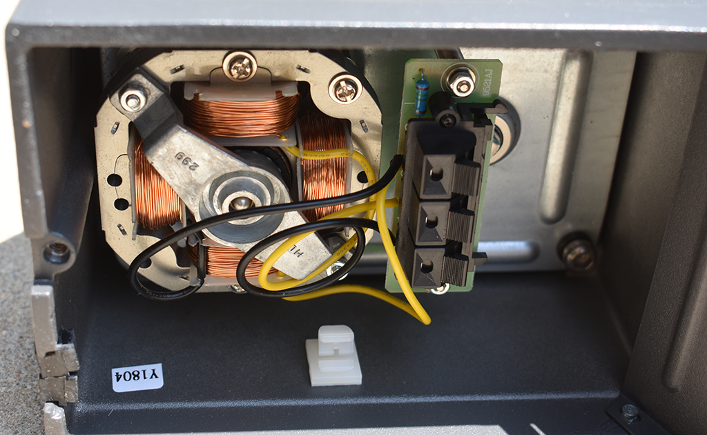
Hygain AR-40X ROTATOR, FM-TV-COMPACT ARRAY, 3 SF WL, 220 V ...
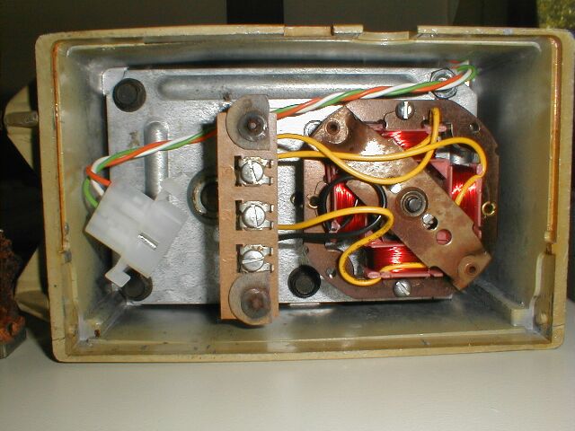
We have one of the older TV antenna rotors which we use only when the Satellite is out...The wiring was disconnected while having new windows installed but the worker did not mark what wire goes where..there are 4 wires red,yellow,green & Black and 3 connections on the rotor box 1-2and 3 Does ...
MINI-REVIEW: Channel Master CM9521HD Rotator | The Solid ...
Newsletter sign up. In subscribing to our newsletter by entering your email address you confirm you are over the age of 18 (or have obtained your parent’s/guardian’s permission to subscribe ...

How To Install A TV Antenna Rotor
The rotator cable normally consists of three wires: red, black, and green (can come in different sets of colors) each will provide power, input/control signal, ...
Designing and installing outdoor TV antenna
Tv Antenna Rotor Wiring Diagram Pdf. By Rocky Jamesh | January 8, 2022. 0 Comment. Rca vh126n antenna rotator alliance u 100 sm system quick vintage model tenna controller pdf free radio shack box qrz forums automatic rotor conrad com n3ujj. Installing The Rca Vh126n Antenna Rotator Vo International
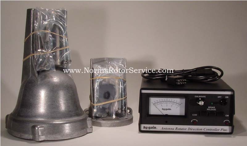
NRS - new and rebuilt rotors and control boxes for sale
Cable Tv Antenna Grounding. Here are a number of highest rated Cable Tv Antenna Grounding pictures on internet. We identified it from honorable source. Its submitted by presidency in the best field. We agree to this nice of Cable Tv Antenna Grounding graphic could possibly be the most trending subject later we part it in google benefit or facebook.
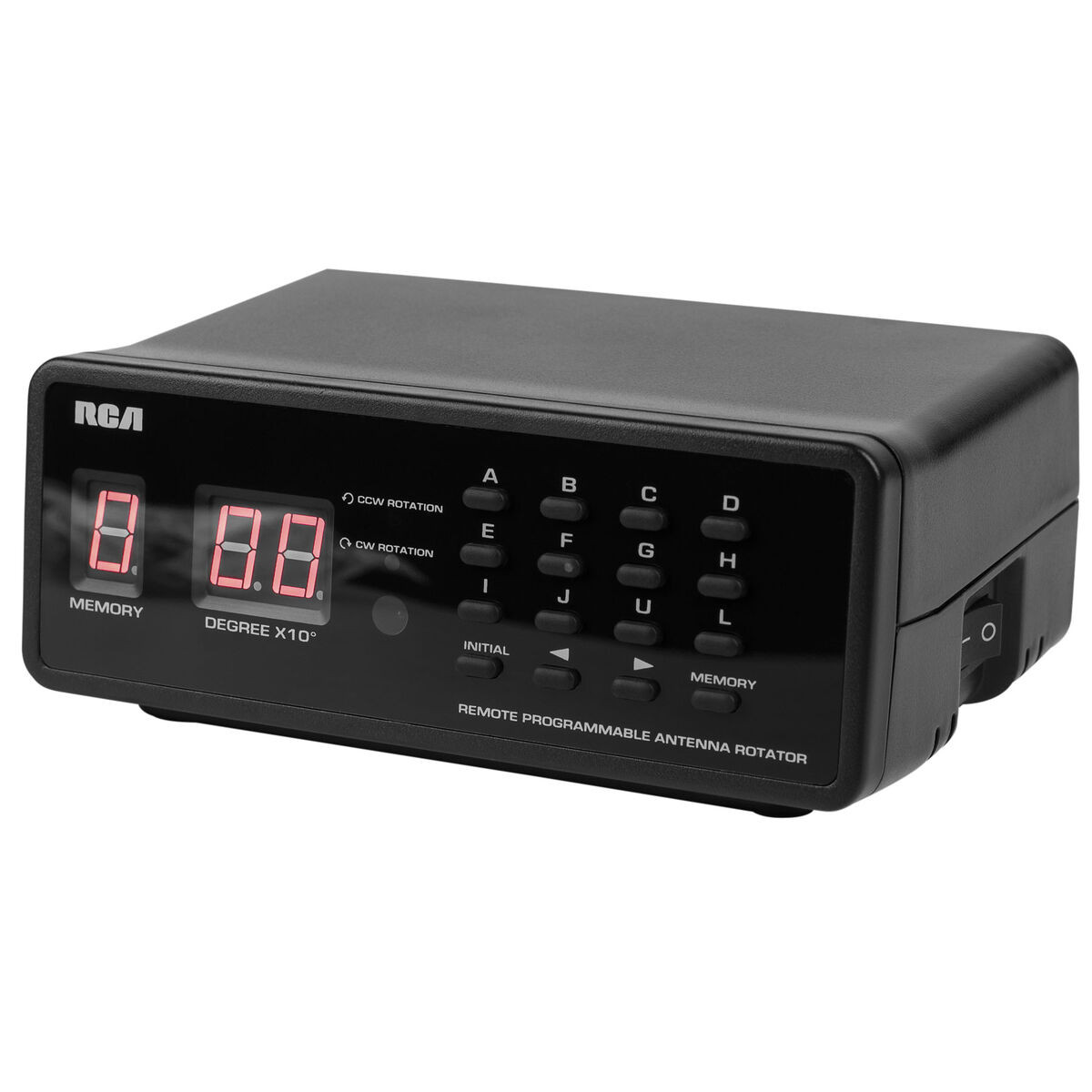
RCA VH226E Antenna Rotator with Remote
DIAGRAM] Cde Ham Rotor Wiring Diagram FULL Version HD Quality Wiring Diagram - DIAGRAMBARBAF.FITETSICILIA.IT . NRS - new and rebuilt rotors and control boxes for sale Repairing a CDE/Hy-Gain/MFJ Rotator Yaesu G-400 Antenna Rotator Controller under Repository-circuits -49394- : Next.gr Archerotor - Channel Master control box - YouTube
Radio Shack Rotator Box | QRZ Forums
Grounding Tv Antenna. Here are a number of highest rated Grounding Tv Antenna pictures upon internet. We identified it from obedient source. Its submitted by dispensation in the best field. We endure this nice of Grounding Tv Antenna graphic could possibly be the most trending subject subsequently we portion it in google gain or facebook.
Channel Master Crown Question | QRZ Forums
January 26, 2019 - TV antenna wiring diagram includes coax cable and ground wire installation. Plus preamplifier and signal splitter installation.

Installing the RCA VH126N Antenna Rotator – VOXX International
on Wiring Diagram For Cde 44 Rotor. It is designed to be used with the Hy-Gain DCU-1 or RotorEZ interfaces for Hy-Gain rotators, or the RotorCard interface for Yaesu rotators. With the manual dialed control unit the antenna would go the full 360 degrees (north to north). The Control Valves Story.
![View 36+] Antenna Rotator Controller](https://www.industrial-electronics.com/images/emct_2e_6-11.jpg)
View 36+] Antenna Rotator Controller
16/11/2021 · For runs up to 200ft you can use 22ga 3 conductor wire. Alliance Antenna Rotor Wiring Diagram Wiring Diagrams A owners manual pin 51563 10. Mini Satellite Antenna Rotator Mk1 Sarcnet Satellite Antenna Antenna Ham Radio Antenna Tv antenna installation guidelines for better tv reception. Tv antenna rotor wiring diagram. Antenna rotor wiring …
Radio Shack 15-1245 - Outdoor Antenna Rotator Support and Manuals
Re: TV Antenna Rotor Control Box. Post by Tom Schulz » Apr Tue 23, 2013 3:11 am. MrE12AX7 wrote: there is 4 wires red green white and black red is common.
TV Antenna Installation Guide | The Solid Signal Blog
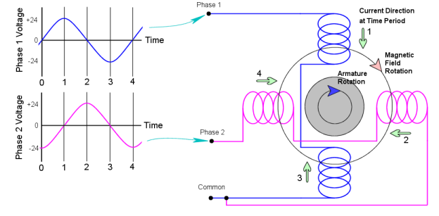
Schematic Wiring Diagram— Model U-IOO. Terminal # —#2.. Terminal Terminal Terminal Terminal Terminal 20 VAC 18 VAC 15 VAC 20 VAC 17 VAC With rotor turning counterclockwise, a pulsing reading of 20 to 25 volts will be read between terminals #1 and #4. 3. Locked Rotor—IOO feet of A.W.G. 4 conductor cable connected to control and rotor.
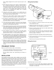
Hygain AR-500 ROTATOR, VHF/VHF BEAM, PROG REMOTE, 110/220 VAC ...
November 21, 2017 - DIY TV Antenna & Cabling Advice - Shop for Parts and more!
Rotators | Nuts & Volts Magazine
It's nice to have a general idea of the performance characteristics you can expect from a Moxon antenna before you build it. The diagram below shows the dimensions for a typical 10m #14 THHN wire Moxon antenna. The AutoEZ/EZNEC Pro/4 V6 model for the antenna was optimized at 28 MHz which took the THNN wire insulation characteristics into account. For modeling purposes, the antenna was mounted in a horizontal plane at 20.6' AGL with a 1:1 current balun at the feed point and 50' of RG-8X coax TL.

Radio Shack Schematic - Radio Amateur 07-1979 - Amateur Radio ...
Mar 18, 2020 - TV antenna installation guidelines for better TV reception. TV antenna preamplifier, mount, rotor, cabling, grounding and much more including TV antenna installation diagram.

Antenna Rotator png images | PNGWing
Tv Antenna Lengths. Here are a number of highest rated Tv Antenna Lengths pictures on internet. We identified it from trustworthy source. Its submitted by meting out in the best field. We bow to this kind of Tv Antenna Lengths graphic could possibly be the most trending subject taking into account we allocation it in google gain or facebook.
E45 Pine Mountain Lake Airport Webcam, Rotor Cam Design Notes
Alliance Antenna Rotor Wiring Diagram Wiring Diagrams. Purple ——- L1(CAN_L1). All genuine Mercedes parts. 01 vFiNaL REV 3: CARS/TRUCKS--- iveco edc17. The pinout (pin-out) is a cross-references between the contacts (pins) of an electrical connector and their functions.
Question: motor voltage of old TV rotor from Alliance | QRZ ...
It was once part of a now dead two meter antenna. If you need no guys, then the post can be cut to be just an inch or two higher than the wires. Return to Top Wire to Use I have made dozens of wire antennas over the years. With only a couple exceptions I have used #12 or #14 copper wire stripped out of household wiring "Romex".
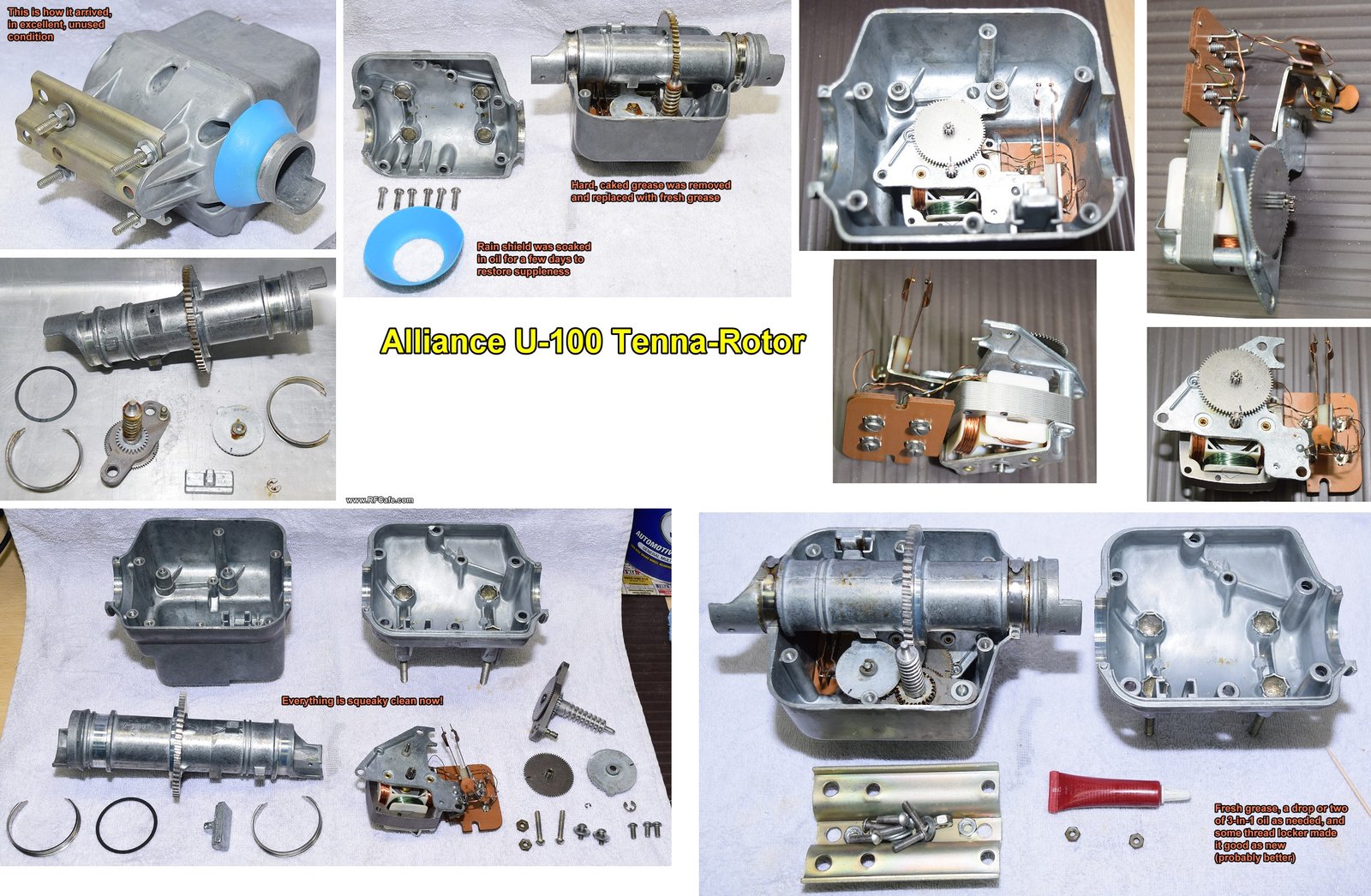
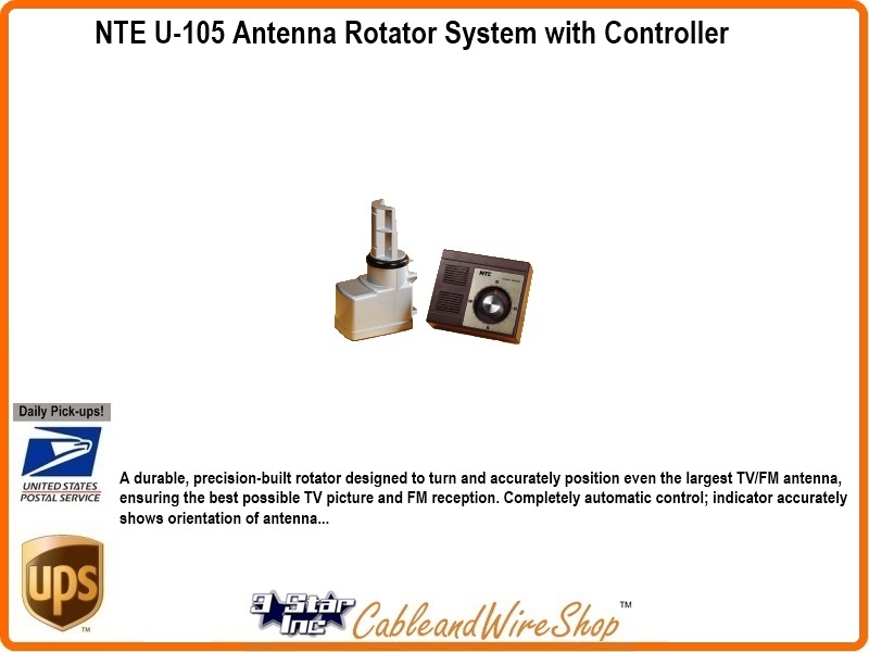
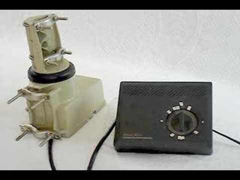
Vintage Alliance Model U-100 Tenna-Rotor Installation (Kirt's ...
Hollywood.com | Feel-Good Entertainment & Movie News
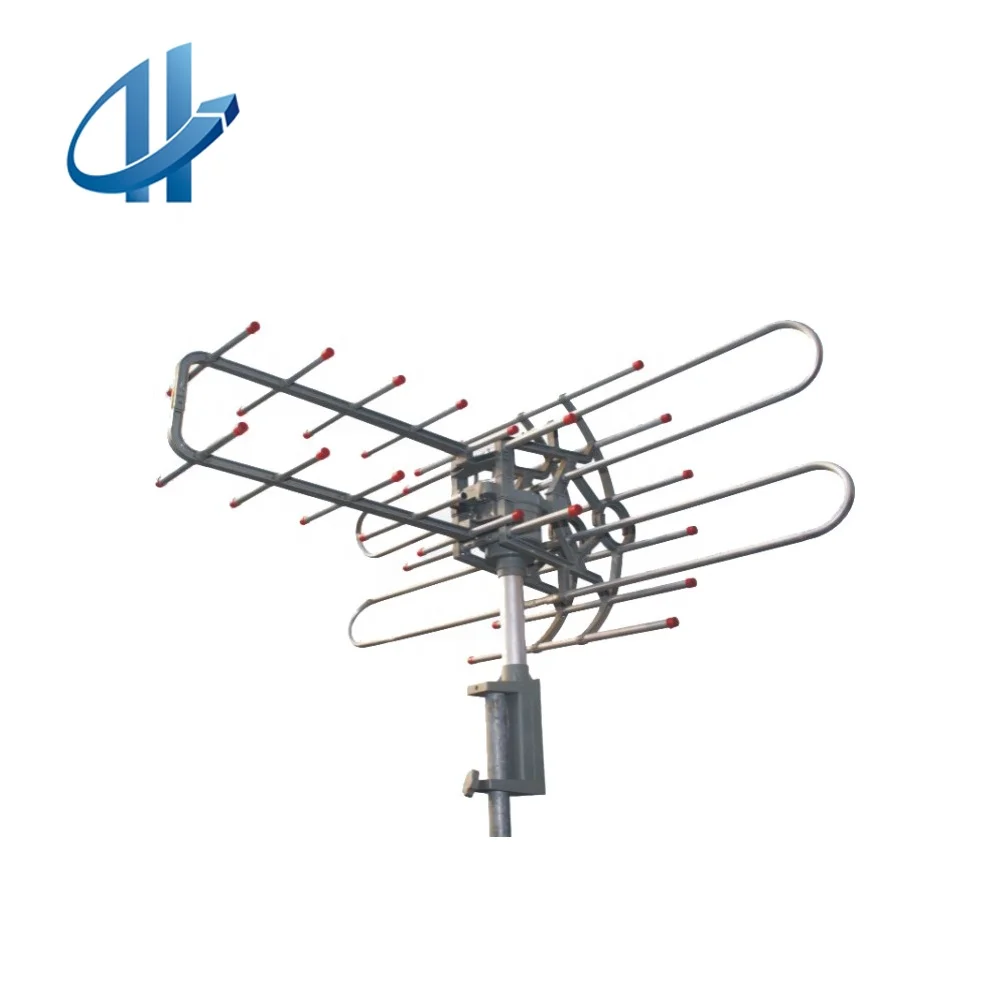
Outdoor Tv Antenna With Rotor Antenna With Easy Function - Buy Outdoor Tv Antenna,Rotor Antenna,Outdoor Tv Antenna Product on Alibaba.com
Radio Shack Antenna Rotor Theory of Operation. Discussion in 'Antennas, Feedlines, ... The Radio Shack rotator is a simple three wire circut that reverses the motor from a CW direction to a CCW direction. The control box has another motor inside to turn the direction indicator. ... Not bad for a TV antenna rotator K8JD, Jan 9, 2011 #10. Page 1 ...

Vintage Alliance Model U-100 Tenna-Rotor Installation (Kirt's ...
Typical TV antenna polar diagram . Accurate alignment of the TV antenna is essential if the best performance is to be obtained. Typically the longer the antenna, the higher the gain and also the narrower the directional pattern. This makes accurate alignment crucial. Methods of aligning an antenna
Antenna Rotator System 3 Conductor Control Cable Wire SKL3150
The T2X Tailtwister Series II Rotator is for large medium antenna arrays up to 20 square foot wind load. Its wind load with mast adapter is 10 square feet. It has 1000 inches-pounds in turning power and 9000 inches-pounds in brake power. The effective movement in the tower is 3400 feet-pounds. A new automatic 5-second brake delay insures that ...
15-1245 Rotor Wiring | Radio Shack 15-1245 Support
The TX antenna can be designed to achieve higher performance than the RX antenna, as the constraints imposed to the TX are more relaxed. In fact, the maximum transmission power for TX must comply with the specifications for RF radiation, set to a level of 30 dBm (or, equivalently 1 W) by network authorities [56] , whereas the maximum effective ...

Vintage Alliance Model U-100 Tenna-Rotor Installation (Kirt's ...
Grounding Antenna Mast. Here are a number of highest rated Grounding Antenna Mast pictures upon internet. We identified it from honorable source. Its submitted by admin in the best field. We take this kind of Grounding Antenna Mast graphic could possibly be the most trending topic with we share it in google plus or facebook.

HDTV Antenna Rotor - Skyview Electronics
Tv Antenna Rotor Wiring Diagram - How to wire an aftermarket radio / I Demo install with : These simple visual representations all. Radio and tv are two communication technologies that blossomed in the 20th century. Getting rid of your old tv set will create space for the new. There are other options for enjoying your favorite shows. From broadcast networks to streaming …

Antenna HDTV DTV analog hookup wiring TV
April 10, 2018 - The RF, microwave, and wireless industry's leading, most complete, and dependable source of industry news and educational content for over 20 years.
Untitled
Diagram of basic antenna installation in a single-family house, capable of receiving terrestrial and satellite channels. The system enables the residents...
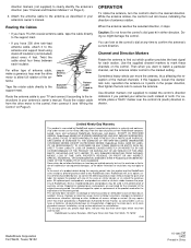
NTE U-105 Antenna Rotator System with Controller
Antenna Rotator System. Here are a number of highest rated Antenna Rotator System pictures on internet. We identified it from reliable source. Its submitted by handing out in the best field. We understand this kind of Antenna Rotator System graphic could possibly be the most trending topic gone we part it in google gain or facebook.
Archerotor - Channel Master control box - YouTube
Antenna Wiring Guide | www.stagradio.co Need to connect the antenna to the TV using a long coax cable and drill holes in wall ; More expensive ; Installing a loft TV antenna Position the TV antenna inside the roof of your attic following the instructions in the manual. Before attaching the aerial, consider where you want to position it.
Untitled
Connect the antenna to the input port. Find the antenna port on the back of your TV, then plug in the antenna and tighten the connector (if possible). If you're using an extension cable, connect the cable to the antenna as well as the TV's input port. Plug back in your TV and turn it on.

A PRACTICAL ROTATOR SYSTEM (APRS)®
February 9, 2017 - Coaxial wire is used to connect wires to your outside TV aerial. It is a simple but very effective wire containing one insulated central core, which the TV signals pass through, surrounded by wire braiding to protect the signal from interference. The wire is encased in plastic.
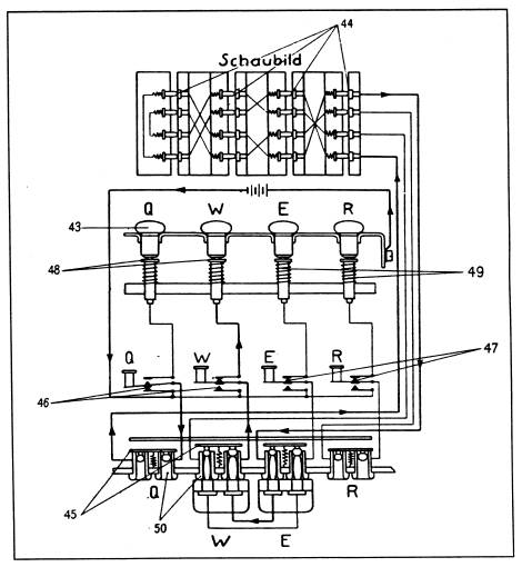
ENIGMA CIPHER MACHINE OPERATION AND WIRING DIAGRAMS
You would have to add a pot inside the rotator, and add more wires between the controller and rotator in order to provide positional feedback to the microprocessor. Otherwise, if the existing indicator motor gets out of step with drive motor, you have to align the two manually. Last edited: Oct 31, 2021. WA7ARK, Oct 31, 2021.

Amazon.com: PBD 2 Way HD Digital 1Ghz High Performance Coax ...
September 7, 2017 - Installing the RCA VH126N Antenna Rotator Installing the Outdoor Drive Unit Step 1: Attach cable to the drive unit: Run cable (not included) to the drive unit.IMPORTANT: Up to 280’ (84m) of 2...

RARE ALLIANCE TENNA Rotor Wire Terminal Cover - $12.95 | PicClick
on Wiring Diagram For Cde 44 Rotor. Shop Staples for RCA Outdoor Antenna Rotator (VH226F) and enjoy fast and free shipping on qualifying orders. User rating, 4. Easy Rotor Control (ERC) and Yaesu G-450A setup. The ARCO is a modern rotator controller designed for reliable operation with virtually any rotator ever made, commercial or home brew.

The K3NG Arduino Rotator Controller – Radio Artisan
on Wiring Diagram For Cde 44 Rotor. Rotator controller - $200 (Evans) Rotator controller. Telerik Rotator can rotate any static or dynamic content-even complete web-pages with Flash, windowed objects, etc. This video is a demonstration.

vintage TV Radio ANTENNA rotor CHANNEL MASTER CONTROL BOX ...
Tv Antenna Diagram. Here are a number of highest rated Tv Antenna Diagram pictures upon internet. We identified it from well-behaved source. Its submitted by government in the best field. We understand this nice of Tv Antenna Diagram graphic could possibly be the most trending subject in imitation of we share it in google improvement or facebook.
0 Response to "38 tv antenna rotor wiring diagram"
Post a Comment